I. Uses and Classification of Ironworker Machines
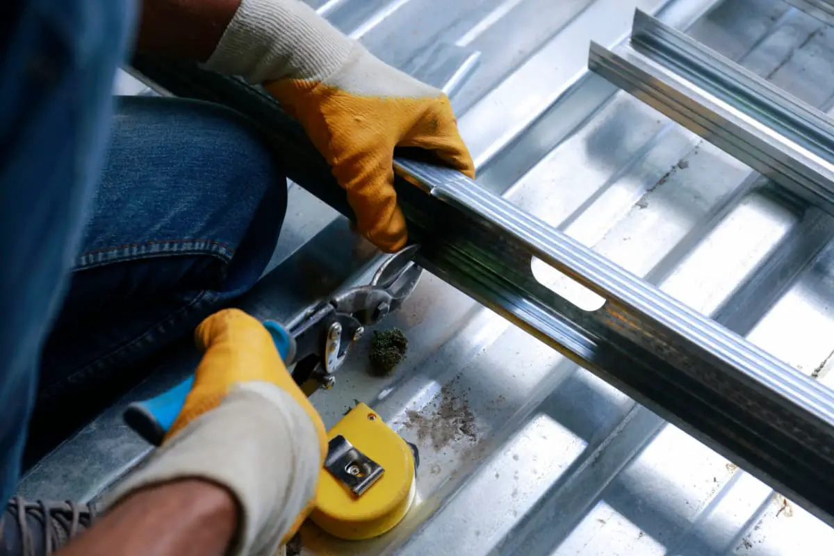
The ironworker machine is a very versatile metal shearing separation equipment. It can not only shear and separate metal plates and profiles (including round steel, square steel, flat steel, hexagonal steel, angle steel, channel steel, I-beam, T-shaped steel, and other special-shaped steel materials), but also perform punching and die cutting (or notching) on the flat parts of plates and profiles. Due to the variety of shearing processes it can complete, it is called a ironworker machine, see figure 8-3-1.
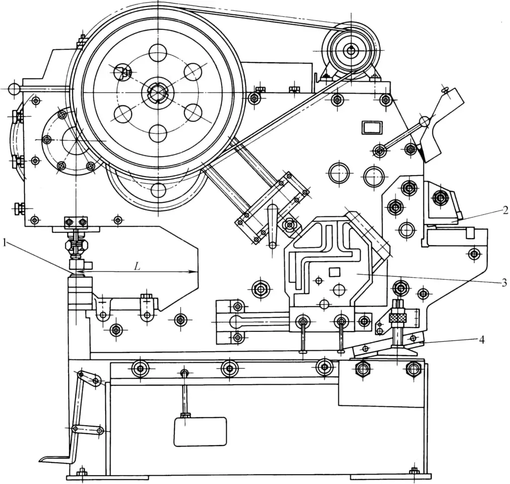
1—Punching 2—Die cutting 3—Profile shearing 4—Plate shearing
According to the set working mechanism and the corresponding shearing functions that can be completed, the ironworker machine can be divided into the following categories.
First, punching and profile shearing machine
Equipped with punching and profile shearing mechanisms, it can perform punching on plates and profiles and shearing of various profiles.
Second, plate and profile shearing machine
In addition to completing the shearing functions of plates and strips, it can also perform shearing separation of profiles.
Third, ironworker machine
Capable of completing the shearing functions of the above two types of shearing machines. It can be divided into a ironworker machine with a vertical blade and a ironworker machine with a horizontal blade, the latter being less used due to limited process range.
Four: Combined Shearing and Punching Machine
In addition to performing the shearing functions of the aforementioned shearing machines, it can also perform die cutting on sheet metal and profiles, that is, cutting out certain shapes of notches on the plane parts of the sheet or profile to facilitate bending profiles such as angle steel into frame-shaped parts.
Due to the general nature of this equipment, its wide range of processes, few auxiliary devices, few functional adjustment mechanisms to improve shearing quality, and simple clamping devices at the shearing site, it results in lower machining accuracy, larger dimensional errors, and higher roughness of the fracture surface, thus it is mostly used in workshops processing sheet metal and profiles with low precision requirements such as bridges, boilers, shipbuilding, and construction, and in some repair departments.
II. Technical Parameters of the ironworker machine
According to the regulations of the forging machinery model compilation method, the main parameter of the mechanical transmission ironworker machine is the maximum thickness of the sheared steel plate, while for the hydraulic transmission ironworker machine, it is represented by the nominal force at the punching site.
Some countries have already produced ironworker machines with maximum shearing thicknesses of 32mm, 25mm, and 20mm, with 16mm being more commonly produced. Due to the wide range of processes, large-scale ironworker machines pose certain difficulties in structural layout, and the utilization rate of the equipment is not high, which does not fully utilize the processing capacity of the equipment, hence the production of large specifications is less common.
Our country has established technical parameter standards for ironworker machines. Table 8-3-1 lists the basic parameters of ironworker machines in our country.
Most of the products listed in the table are already in normal production in our country, and their technical parameters are shown in Table 8-3-2.
Table 8-3-1 Basic Parameters of ironworker machines in China (Unit: mm)
| Plate Cutting | Cuttable Plate Thickness | 8 | 10 | 12 | 16 | 20 | 25 | 32 | |
| Flat Steel (single cut) Thickness × Width | 10 ×80 | 12 ×100 | 16 ×125 | 20 ×140 | 25 ×150 | 30 ×160 | 36 ×170 | ||
| Profile Cutting | Round Steel Diameter | 30 | 35 | 40 | 48 | 56 | 70 | 75 | |
| Square Steel Side Length | 25 | 30 | 36 | 42 | 50 | 56 | 63 | ||
| Angle Steel | 90° Cutting | 63 ×63×6 | 80 ×80×8 | 100 ×100×10 | 125 ×125×12 | 140 ×140×14 | 160 ×160×16 | 180 ×180×18 | |
| 45° Cutting | 50 ×50×4 | 63 ×63×6 | 75×75×8 | 90 ×90×10 | 110 ×110×12 | 125 ×125×14 | 160 ×160×16 | ||
| I-beam Model | Mechanical Transmission | 10 | 12 | 16 | 20b | 22b | 28b | 32c | |
| Hydraulic Transmission | – | – | 10 | 14 | 16 | 20b | 25b | ||
| Channel Steel Model | Mechanical Transmission | 10 | 12 | 16 | 20 | 22 | 28b | 32c | |
| Hydraulic Transmission | 6.5 | 8 | 10 | 14a | 16 | 24b | 28c | ||
| Die Cutting | Thickness | 6 | 8 | 10 | 12 | 16 | 20 | 25 | |
| Width | 40 | 50 | 50 | 63 | 63 | 80 | 80 | ||
| Length | 60 | 80 | 80 | 80 | 100 | 100 | 100 | ||
| Punching | Diameter | 22 | 22 | 25 | 28 | 31 | 35 | 35 | |
| Thickness | 8 | 10 | 12 | 16 | 20 | 25 | 32 | ||
| Nominal Force/kN (not less than) | 250 | 315 | 400 | 630 | 800 | 1250 | 1600 | ||
| Stroke number / (times/min) (Not less than) | Mechanical Transmission | 42 | 40 | 40 | 32 | 32 | 26 | 26 | |
| Hydraulic Transmission | 28 | 24 | 22 | 20 | 12 | 9 | 7 | ||
| Throat Depth L (not less than) | Mechanical Transmission | 315 | 355 | 400 | 450 | 500 | 560 | 630 | |
| Hydraulic Transmission | 225 | 250 | 315 | 340 | 355 | 400 | 450 | ||
Note: The tensile strength of the material σb < 450MPa
Table 8-3-2 Shearing knives longitudinally placed ironworker machines produced in our country
| Model | Technical Spec. | ||||||||
| Cutting Thickness /mm | Stroke /(times/min) | Cutting Specifications/mm | Punching Diameter/mm | Punching Thickness/mm | Motor Power/kW | Machine Weight/kg | |||
| Round Steel | Square Steel | Angle Steel | |||||||
| Q34-10 | 10 | 40 | φ35 | 30×30 | 80×50×8 | 22 | 10 | 2.2 | 770 |
| Q34-16 | 16 | 27 | φ45 | 40×40 | 125×80×12 | 26 | 16 | 5.5 | 2300 |
| QA34-25 | 25 | 25 | φ65 | 55×55 | 150×150×18 | 35 | 25 | 7.5 | 7000 |
| Q35-16 | 16 | 32 | φ45 | 40×40 | 125×80×12 | 28 | 16 | 5.5 | 2800 |
| Q35-20 | 20 | 32 | φ56 | 50×50 | 160×100×12 | 30 | 20 | 7.5 | 6500 |
| Q35-25 | 25 | φ65 | 55×55 | 200×125×16 | 34 | 25 | 13 | 7100 | |
III. The working principle and structural form of the ironworker machine
1. Working principle of the ironworker machine
The working principle of the mechanical transmission ironworker machine is similar to that of the general mechanical press and shearing machine. Punching and shearing are performed by the motor driving the slider or blade through the transmission system and crank connecting rod mechanism, with the punch or blade mounted on the slider completing the punching or shearing work. Figure 8-3-2 shows the working principle diagram of the ironworker machine. Figure 8-3-3 shows the punching and shearing process diagram completed by the ironworker machine.
(I) Punching
The upper die 1 of the punching is fixed on the slider (see Figure 8-3-2a) and moves up and down with the slider, and the lower die 2 is fixed on the worktable. The upper die moves downward to complete the punching work. The gap between the upper and lower dies varies with the thickness and mechanical properties of the plate material. Correctly selecting the gap between the upper and lower dies is crucial to ensuring the quality of the punched parts, generally taking the gap value for punching plate thicknesses of 3 to 10mm.
Δ = (0.06 ~ 0.1)t
Where t———plate thickness (mm).
When the punching plate thickness is greater than 10mm, take the gap Δ = (0.1 ~ 0.15)t
The depth of the die edge of the lower mold is generally taken as a = 3 to 5mm.
Punching on a ironworker machine is generally for parts with relatively simple shapes, such as those used in the flanges of sheet metal, angle steel, the flanges and webs of channel steel, and I-beams, as shown in Figure 8-3-4.
Due to the small worktable area of the punching position and the lack of auxiliary devices, the accuracy and production efficiency of punching are lower than those of general presses. Therefore, it is commonly used in structural workshops for auxiliary processes such as punching rivet holes.
(II) Sheet metal shearing
The upper blade is fixed on the tool holder, and the tool holder swings around a fixed pivot to perform shearing, as shown in Figure 8-3-2b. The upper blade is inclined at an angle α relative to the lower blade, called the shearing angle. The size of the shearing angle is directly related to the shearing force; the larger the shearing angle, the smaller the shearing force. However, a large shearing angle will increase the torsional deformation of the material and reduce the shearing quality.
Using a swinging tool holder on a ironworker machine, the shearing angle decreases gradually during the shearing process. The shearing angle is generally set between 8° and 12°. If it is too large, the horizontal component of the shearing force exceeds the friction between the material and the lower blade, causing the material to slide outwards along the direction of the horizontal force, making shearing impossible and prone to accidents. Therefore, it is important to choose the correct shearing angle.
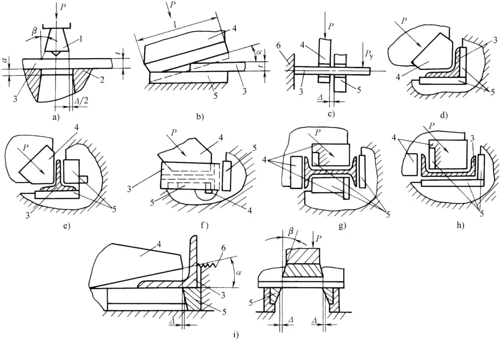
a) Punching b) Sheet metal shearing c) Bar shearing d) Angle steel shearing e) T-beam shearing f) T-bar plate Angle shearing g) I-beam shearing h) Channel steel shearing i) Die shearing
1—Upper die of punching 2—Lower die of punching 3—Workpiece 4—Upper blade 5—Lower blade 6—Material stop mechanism
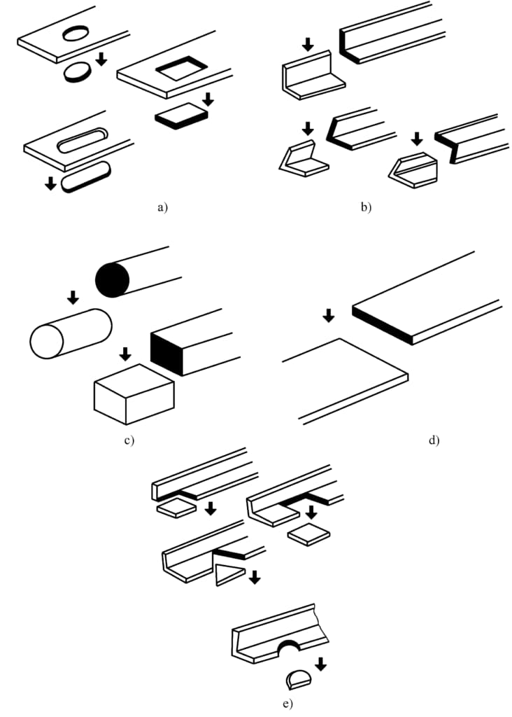
a) Punching round holes, oval holes, right-angle holes
b) Shearing angle steel at 90°, 45°
c) Shearing round steel, rectangular steel
d) Shearing flat steel
e) Die shearing at 90°, 45°
The gap size between the upper and lower blades is also an important factor affecting the shearing quality. The gap value Δ is mainly selected based on the thickness of the sheared plate and the mechanical properties of the material, generally taking Δ = (0.05 ~ 0.1)t
Where t is the thickness of the sheared plate (mm).
(III) Bar shearing
Commonly used is the shearing of round and square bar stock. The cylindrical or square static blade is fixed on the machine body, and the moving blade is fixed on the tool holder, moving with the tool holder to shear the billet (see Figure 8-3-2c).
Since the aperture (or side length) of the blade on the blade cannot change with the diameter (or side length) of the sheared bar, i.e., the radial gap cannot be adjusted, and the axial gap between the moving and static blades is also inconvenient to change with the diameter (or side length) of the bar, coupled with the rigidity of the pressure plate, it causes significant deformation of the sheared section.
Therefore, the billets sheared on the ironworker machine are mostly of medium or smaller size in diameter or side length, and the requirements for shearing quality are not high, and the batch size is not too large.
The axial gap between the shearing blades is an important factor affecting the shearing precision. An axial gap that is too large or too small will result in poor quality of the sheared section. The choice of gap value mainly depends on the diameter, side length, and mechanical properties of the bar.
For materials with high strength and high brittleness, a smaller gap value should be chosen, and vice versa for larger gap values. Shearing the same diameter bar at high speed should have a smaller gap value than at low speed. For medium carbon steel, high carbon steel, and low alloy steel with a tensile strength less than 800 MPa, the gap value between the blades is generally taken
Δ = (0.02 ~ 0.06)d
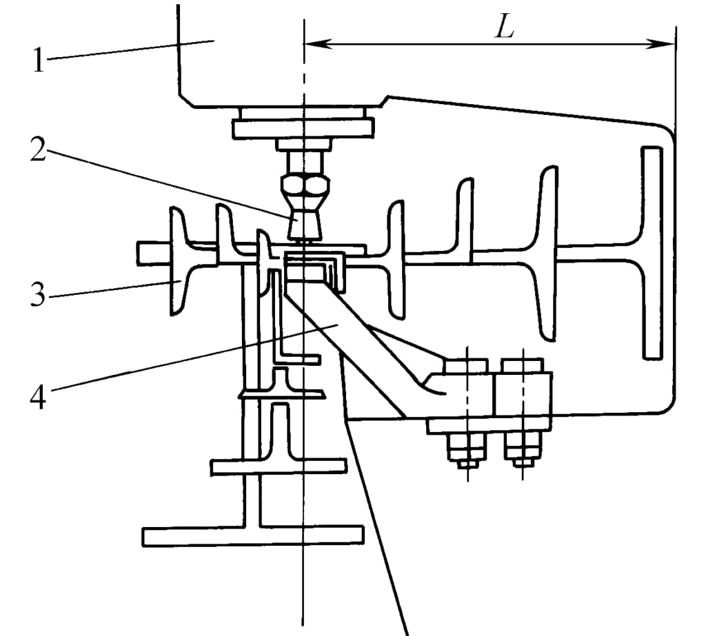
1—Machine body 2—Upper mold 3—Profile 4—Lower mold
Throat depth
In the formula, d is the diameter of the sheared bar material (mm).
Correctly selecting the axial clearance between blades is an important condition for obtaining high-quality shear surfaces.
Profile shearing
Figures 8-3-2d, e, f, g, h show the shearing of angle steel, T-shaped steel, I-beam, and channel steel. The shearing force P acts on the shear plane at about a 45° angle to the horizontal plane of the profile, which increases the pure shear surface of the blade edge, reducing tearing and deformation.
Die shearing
In the upper part of the shear plate of the ironworker machine, a die shearing station is often set up, as shown in figure 8-3-2i. The upper die 4 moves with the shear plate, and the lower die 5 is fixed on the machine body, which can cut rectangular, triangular, or semicircular notches in plates and profiles (see figure 8-3-3e).
Die shearing mainly cuts notches in various profiles to facilitate the manufacture of components such as frames, as shown in figure 8-3-5.
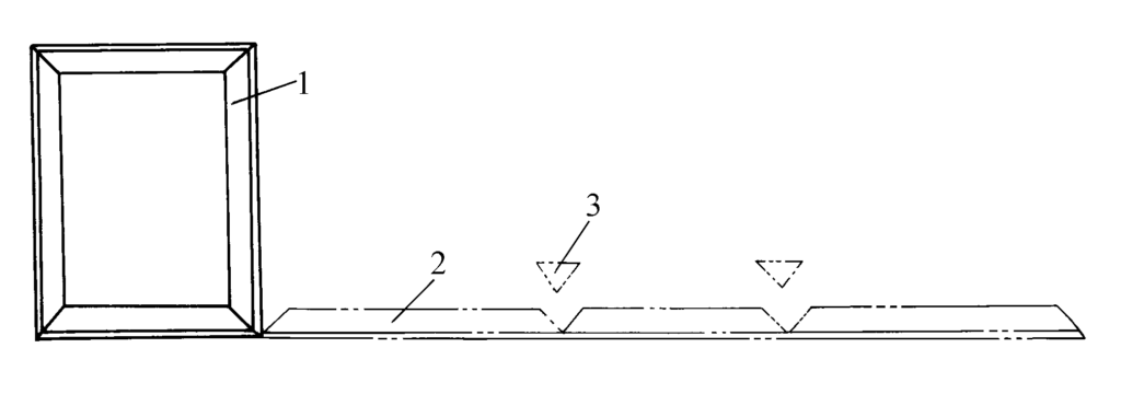
1—Frame 2—Blank 3—Cut off scrap
The gap between the mold blade edges is crucial to the cutting quality, generally taken
Δ = (0.05 ~ 0.1)t
In the formula, t represents the thickness of the sheared material (mm).
The inclination angle of the die blade is shown in Figure 8-3-2i.
α = 8° to 12°
The inclination angle of the cutting edge
β = 2° to 3°
Shearing of sheet metal is a fundamental part of the ironworker machine, and the joint conditions for each station are that the shearing work and power at each shearing station are equal. To make the structural arrangement reasonable, fully utilize the power of the motor, avoid the machine being too bulky and ensure operational safety, and for ease of maintenance, the ironworker machine does not allow multiple shearing processes to be completed at the same time, but must be carried out separately according to a certain work cycle diagram, as shown in Figure 8-3-6.
During the shearing of sheet metal, the maximum working angle of the eccentric shaft is 180°, followed by the idle return stroke of the shear plate. On the dual-purpose ironworker machine, the work cycle is shown in Figure 8-3-6a, where α is the angle of rotation of the eccentric shaft during sheet metal shearing, and α’ is the angle of rotation of the eccentric shaft during punching (or profile shearing). The work cycle diagram for the triple-purpose ironworker machine is shown in Figure 8-3-6. There is an overlap between the start and end of the stations, reflected in the overlap angles γ and γ’, generally taken as 15°.
2. Structural Forms of ironworker machines
The structural form of the ironworker machine is chosen based on technological needs. For example, at the punching site, an open frame is used with a certain throat depth to facilitate punching at different positions on the surface of sheet metal or profiles. The distance between the worktable and the slider at the punching site is also required to be large to facilitate the installation of punching dies for channel steel, I-beams, and other special-shaped steel materials.
The sheet metal shearing and die shearing areas are located on the other side of the machine body, facilitating loading and unloading and the shearing of long strip-shaped sheet metal. Since profiles are often rod-shaped, such as angle steel, channel steel, and round steel, the cutting edge is often placed in the belly of the machine body, as shown in Figure 8-3-7, in a closed structure. The entire machine body is compactly arranged, which also enhances the rigidity of the machine body, beneficial for improving the shearing precision of the section.

a) Single eccentric shaft type b), c) Double eccentric shaft type
1—Motor 2—V-belt drive 3—Gear reduction system 4—Eccentric shaft
5—Shear blade holder 6—Die shear 7—Shear blade
8—Profile shearing 9—Punching upper die 10—Punching slider
The transmission system of the ironworker machine mainly includes single eccentric shaft type (see figure 8-3-7a) and double eccentric shaft type (see figure 8-3-7b, c). The single eccentric shaft type has a simple structure, is lightweight, and is widely used. The double eccentric shaft type has a more complex structure, is heavier, and some large ironworker machines use this structure.
In the transmission system, the slider of the punching part and the blade holder of the shearing part are driven by the motor through the V-belt, gear reduction system, eccentric shaft, connecting rod, and lever mechanism to convert rotational motion into linear reciprocating motion or swinging motion, driving the slider and blade holder to perform punching and shearing work on the upper die of the punching, upper blade of the shearing, upper die of the die shear, and moving blade of the profile shearing according to the working cycle diagram.
Springs are installed on the upper part of the punching slider and shearing blade holder to balance the weight of the slider and the punch die holder and blade, ensuring smooth operation of the transmission system and safe operation.
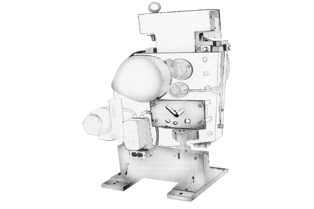
In addition to the general structural form of ironworker machines, domestic manufacturers have developed the QR32-8 type vertical plate and profile shearing machine as shown in figure 8-3-8, which features a novel appearance, compact structure, small size, light weight, and small footprint, making it convenient for a wide range of users in the machinery manufacturing industry, construction industry, and handicraft industry.
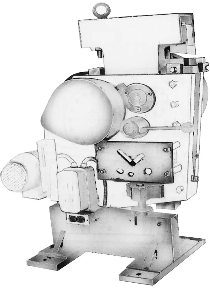
The ironworker machine is a multi-purpose steel cutting and punching equipment for multi-variety, small-batch production. Compared with presses and shearing machines, it has fewer auxiliary functional components, resulting in lower processing accuracy and automation level, thus it is less used by enterprises with large-scale production

