CO2 Laser Cutting Thickness, Speed & Power Chart (25-200W)
How can manufacturers achieve precise and efficient CO2 laser cutting for various materials? This article explores the relationship between laser…
Have you ever struggled with laser cutting precision? Whether you’re dealing with burrs on low carbon steel or incomplete cuts, troubleshooting these issues can be daunting. This guide breaks down common laser cutting problems, from piercing techniques to deformation in small holes, and provides practical solutions to improve your cutting quality. Dive in to learn how to optimize your laser cutting process and ensure flawless results every time.
Every thermal cutting technique typically requires creating a small hole in the material, except for a few instances where the process can start from the edge of the sheet.
Previously, in laser punch press combinations, a punch would initially create a hole, followed by laser cutting starting from that small hole. For laser cutting machines without punching devices, there are two basic methods of piercing:
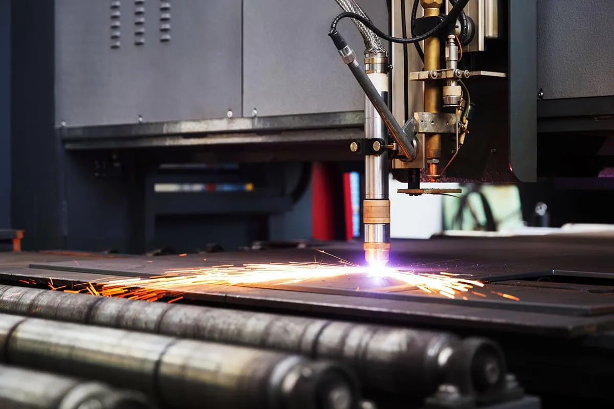
Blast Piercing – Continuous laser irradiation forms a pit at the center of the material, then an oxygen stream co-axial with the laser beam swiftly removes the molten material, forming a hole.
Generally, the hole size is related to the sheet thickness, with the average blast piercing diameter being half the thickness.
Thus, blast piercing creates larger, non-circular holes in thicker sheets, which are inappropriate for parts requiring high precision and are only suitable for scrap materials.
Additionally, since the oxygen pressure used for piercing is the same as that used for cutting, splattering is significant.
Pulse Piercing – A high peak power pulse laser melts or vaporizes a small amount of material. Air or nitrogen is often used as an auxiliary gas to minimize hole expansion due to exothermic oxidation, and the gas pressure is lower than the oxygen pressure used during cutting.
Each pulse laser produces a small particle jet that gradually penetrates the material, therefore, piercing thick sheets can take a few seconds. Once piercing is complete, the auxiliary gas is immediately replaced with oxygen for cutting.
This method produces smaller holes and superior piercing quality compared to blast piercing. The lasers used for this not only need to have high output power, but more importantly, the temporal and spatial characteristics of the beam must be optimal.
Consequently, typical transverse flow CO2 lasers are generally unsuitable for laser cutting requirements. Furthermore, pulse piercing requires a reliable gas control system to manage the gas type, gas pressure changes, and piercing time control.
In cases using pulse piercing, in order to obtain high-quality cuts, the transition from pulse piercing at a standstill to continuous cutting at a constant speed should be given careful attention.
Theoretically, cutting conditions such as focal length, nozzle position, and gas pressure can be altered during the acceleration phase, but practically, the timeframe is too short for these changes to be feasible.
In industrial production, adjusting the average laser power is a more realistic approach, specifically by modifying pulse width, changing pulse frequency, or simultaneously adjusting pulse width and frequency. Practical results indicate that the third method provides the best outcome.
This is due to the machine tool (specifically high power laser cutters) not utilizing a blasting perforation method when processing small holes, but instead employing a pulsating piercing (soft puncture) method.
This results in overly concentrated laser energy in a small area, burning and deforming the non-processing area and affecting the quality of the work. In these instances, we should modify the machining program from pulsating piercing (soft puncture) to blasting perforation (ordinary puncture) to rectify the issue.
On the contrary, for lower power laser cutters, it’s best to use the pulsating piercing method to achieve better surface smoothness during small hole processing.
Based on the working and design principles of CO2 laser cutting, we’ve analyzed the following main reasons that contribute to the formation of burrs on the workpieces:
The occurrence of the above situation primarily considers factors leading to burr formation during low carbon steel cutting.
However, simply increasing the cutting speed is not the solution as it sometimes results in incomplete sheet penetration, a situation particularly prominent when processing aluminum-zinc coated sheets.
At this point, it is necessary to consider other factors related to the machine tool, such as whether the nozzle needs to be replaced or if there is instability in the rail movement.
Upon analysis, it is found that the following situations are the primary causes of unstable processing:
Additionally, it is important to note that when the L3030 laser cutting machine cuts carbon steel sheets above 5mm, a 7.5″ focal length laser lens needs to be replaced.
This situation can affect the smoothness of the cutting section and the processing quality of the parts.
In this case, with all other parameters being normal, the following should be considered: the wear of the laser head nozzle (NOZZEL) – the nozzle should be replaced in a timely manner.
If a new nozzle cannot be replaced, the pressure of the cutting working gas should be increased; the threads at the nozzle and laser head connection are loose.
Cutting should be immediately paused, the connection status of the laser head checked, and the threads properly reengaged.
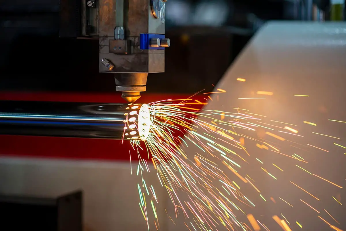
The working principle of the laser beam during laser cutting processing is as follows: In the process, a pit forms at the center of the material after continuous laser irradiation. This pit is then quickly removed by a co-axial working airflow, creating a hole in the material.
This hole is akin to the threading hole in wire cutting, where the laser beam starts its contour cutting.
Typically, the path direction of the flying optical path laser beam is perpendicular to the tangent direction of the cutting contour of the processed part.
Therefore, from the moment the laser beam begins to penetrate the steel plate until it enters the contour cutting of the part, there is a significant change in its cutting speed in the vector direction— a 90° rotation.
The direction shifts from being perpendicular to the cutting contour’s tangent to coinciding with it, i.e., an angle of 0° with the contour tangent. This swift change in the laser beam’s vector direction in a short time results in a rather rough cut surface on the processed material.
As such, this aspect needs to be considered when using laser cutting to process parts.
Generally, if there are no roughness requirements for the cut surface of the part in the design, manual adjustments are not necessary during laser cutting programming. The control software can automatically generate piercing points.
However, if the design requires a higher degree of roughness for the cut surface of the processed part, this issue must be addressed.
Typically, manual adjustments to the starting position of the laser beam are needed during the programming of the laser cutting procedure, i.e., manual control of the piercing points.
The originally generated piercing points in the laser program need to be moved to a reasonable position to meet the surface accuracy requirements of the processed part.
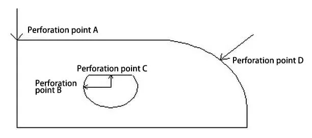
As shown in Figure 1, if this component requires precision in the arc, the starting points (piercing points) for the laser cutting program should be set at A and C, not at B and D. However, if the precision required for this component is only for the straight edges, the starting points for the laser cutting program should be set at B and D, not at A and C.
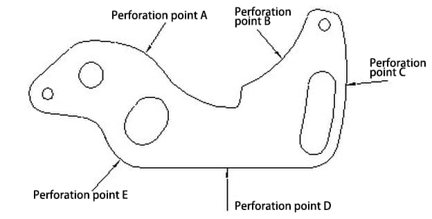
As shown in Figure 2, if the design of this component requires precision in the arc, the starting point (piercing point) of the laser cutting program can only be set at point D.
However, if the part only requires precision on the straight edges, we can select any point other than D as the starting point (piercing point) when creating the laser cutting program.
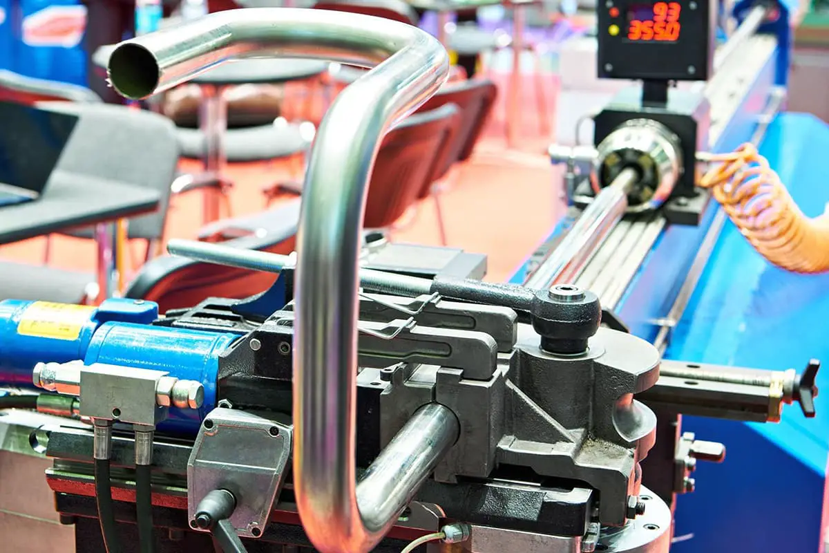
Laser cutting of sheet metal parts is an advanced manufacturing technique. It not only significantly reduces the development cycle and the cost of mold manufacturing, but also improves quality and production efficiency, facilitating technical and equipment innovation in the manufacturing industry.
In practical applications, it is essential for us to continuously accumulate experience, deepen our understanding, and practice. In this way, this new technology can contribute as it should to increase our productivity.