Machining Difficult Materials: Expert Tips and Techniques
Imagine trying to carve a sculpture from a diamond. Machining difficult materials, like titanium and Inconel, presents similar challenges in…
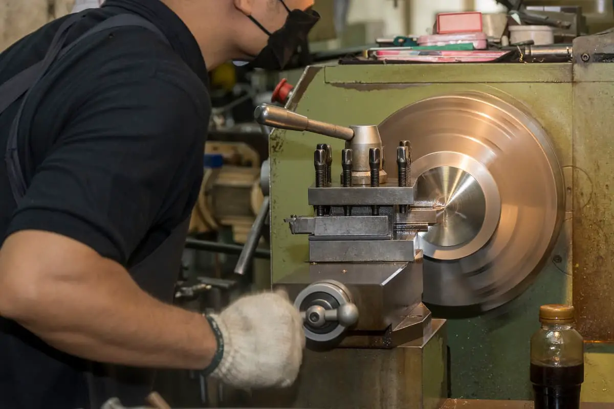
The method of cutting processing by utilizing the rotational movement of the workpiece and the movement of the tool on the lathe is called turning processing. The rotational movement of the workpiece is the main movement, and the movement of the tool on the machine tool is the feed movement. Turning processing is the most basic method of metal cutting processing and is widely used in the machinery manufacturing industry.
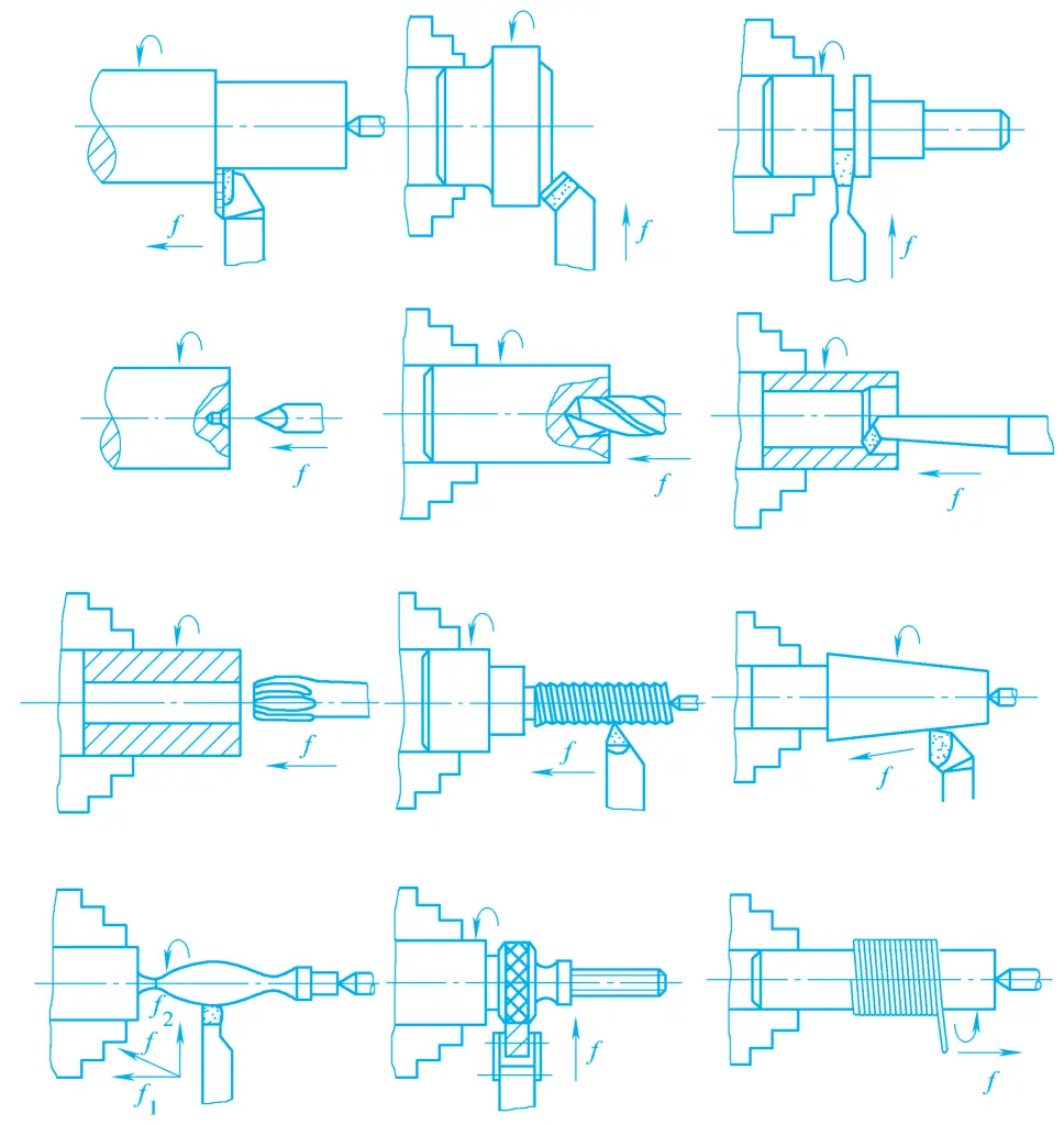
Turning processing is mainly used for processing various rotating surfaces and the end faces of rotating bodies, and can also perform cutting off, grooving, threading, drilling, reaming, and boring, as shown in Figure 1. If accessories are installed on the lathe or special lathe fixtures are used, parts with more complex shapes can be processed; if the lathe is appropriately modified, it can also achieve boring, grinding, polishing, and other processing.
During turning, the rotation of the workpiece is generally not limited by inertial forces, and the workpiece is always in contact with the turning tool during the machining process, basically without impact phenomena, so very high cutting speeds can be used. In addition, the length of the tool holder extending out of the tool post can be very short, the size of the tool holder can be larger, and a large back cutting depth and feed rate can be selected, hence the high productivity.
The structure of the turning tool is simple, and sharpening and installation are very convenient. In addition, many lathe fixtures have been produced as lathe accessories, which can meet the clamping needs of general parts, the production preparation time is short, hence the machining cost of turning is lower.
Depending on the usage requirements of the parts, turning can achieve low, medium, and quite high machining accuracy.
When the blank is a free forging or a large casting, its machining allowance is large and uneven, rough turning can remove most of the allowance, reduce geometric errors, and the dimensional tolerance grade for rough turning is generally IT18~IT15, surface roughness Ra>80μm.
Medium and small forgings and castings can be directly semi-rough turned, the tolerance grade after semi-rough turning is IT13~IT11, and the surface roughness value is Ra30~12.5μm.
Workpieces that do not require high dimensional accuracy or before the fine machining process can be arranged for semi-finish turning, the tolerance grade after semi-finish turning is IT10~IT8, surface roughness value is Ra6.3~3.2μm.
Generally as the final process or pre-machining process for finishing, the tolerance grade of the workpiece after finish turning can reach IT8~IT7, surface roughness value is Ra1.6~0.8μm.
High-speed precision turning is the method of fine machining workpieces with hard alloy, cubic boron nitride or diamond tools, using high cutting speeds, small back cutting depth, and feed rate.
For non-ferrous metals, if grinding is used, the chips are easy to stick to the surface of the grinding wheel, making it impossible to proceed with grinding normally. However, on a high-precision lathe, using diamond tools for high-speed cutting can achieve very good results, the dimensional tolerance grade can generally reach IT6~IT5, surface roughness value is Ra1.0~0.1μm.
In addition, CNC lathes can machine parts with very high geometric accuracy requirements. On horizontal lathes, the coaxiality of steps, the perpendicularity of the end face to the axis, etc., are easy to ensure, but for some parts with many steps, strict positioning dimensions or high shape accuracy requirements, such as spherical surfaces, special shapes, etc., are not easy to ensure on horizontal lathes.
At this time, CNC lathes can be used. CNC lathes can complete complex surfaces that are difficult or impossible to machine on general lathes, can achieve very high machining accuracy, and the product quality is stable, with high productivity.
In ordinary mechanical manufacturing plants, lathes account for the largest proportion of metal cutting machine tools, about 20%~35% of the total number of metal cutting machine tools, and there are many types.
Lathes can be divided into instrument lathes, automatic lathes, semi-automatic lathes, turret lathes, vertical lathes, floor lathes, horizontal lathes, copying lathes, crankshaft and camshaft lathes, gear shaping lathes, etc., among which horizontal lathes are the most widely used.
The following takes the CA6140 model horizontal lathe (see figure 2) as an example to explain the components of the horizontal lathe and their functions.
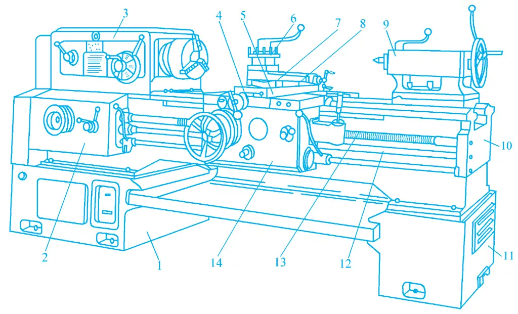
1, 11—Legs
2—Feed box
3—Headstock
4—Saddle
5—Middle slide board
6—Tool holder
7—Rotary table
8—Small slide board
9—Tailstock
10—Bed
12—Smooth rod
13—Lead screw
14—Slide box
The spindle box 3 is fixed on the left end of the bed 10, and its interior is equipped with a spindle and transmission shaft, as well as mechanisms for speed change, direction change, lubrication, etc. It is driven by an electric motor through a speed change mechanism to rotate the spindle, achieving the main motion, and obtaining the required speed and direction. The front end of the spindle can be equipped with a three-jaw self-centering chuck, four-jaw single-action chuck, and other fixtures for clamping workpieces.
The feed box 2 is fixed on the left front side of the bed 10, used to change the lead of the thread being machined or the feed amount of the power feed.
The slide box 14 is fixed at the bottom of the saddle 4, its function is to transmit the motion from the feed box through the smooth rod or lead screw to the tool holder, making the tool holder perform longitudinal feed, transverse feed, or threading motion.
In addition, by operating the longitudinal and transverse handles and the electrical buttons above, a high-speed electric motor installed in the slide box can be started, realizing the longitudinal and transverse rapid movement of the tool holder. The slide box is equipped with various handles and buttons, which can conveniently operate the machine tool.
The saddle 4 is located on the upper part of the bed 10 and can move longitudinally along the guide rails on the bed. It is equipped with a middle slide board 5, rotary table 7, small slide board 8, and tool holder 6, allowing the tool to perform longitudinal, transverse, or diagonal feed motion.
The tailstock 9 is installed on the tail guide rail of the bed 10 and can be adjusted longitudinally along the guide rail, then fixed in the required position to accommodate workpieces of different lengths. The sleeve on the tailstock can be equipped with centers and various hole machining tools to support the workpiece or perform hole machining on the workpiece. Rotating the handwheel moves the sleeve, achieving longitudinal feed of the tool.
The bed 10 is fixed on the left bed leg 1 and the right bed leg 11. The bed is the basic supporting part of the lathe, with all the main components of the lathe installed on it. It maintains the accurate relative positions between the components and bears the cutting force and the weight of the components.
The vertical lathe is mainly used for machining large or heavy parts with large radial dimensions and relatively small axial dimensions, and complex shapes. It is an indispensable processing equipment in factories manufacturing heavy machinery such as steam turbines, heavy-duty electric motors, mining and metallurgy, and is also commonly used in general machinery factories.
The main feature of the vertical lathe structure is that the spindle is arranged vertically, and there is a circular worktable for clamping workpieces (see Figure 3). Since the worktable is arranged horizontally, it is very convenient to clamp bulky parts.
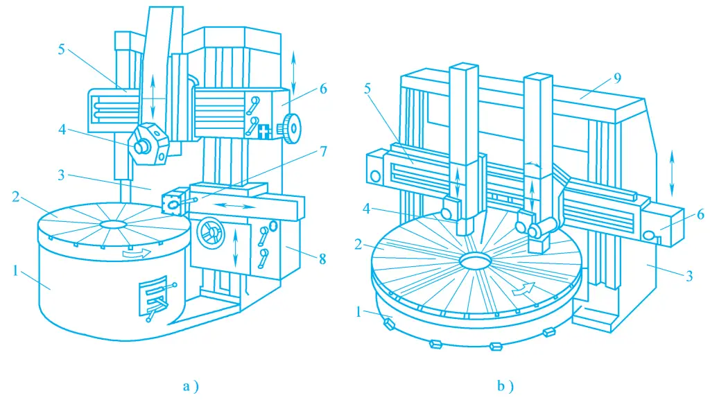
a) Single column vertical lathe
b) Double column vertical lathe
1—Base
2—Worktable
3—Column
4—Vertical tool post
5—Crossbeam
6—Vertical tool post feed box
7—Side tool post
8—Side tool post feed box
9—Top beam
Vertical lathes come in two types: single column and double column. Figure 3a is of the single-column type, which processes workpieces with a smaller diameter, generally less than 1600mm. The worktable 2 is driven to rotate by the vertical spindle installed inside the base 1, with the workpiece clamped on the worktable and rotating with it, which is the main motion.
The feed motion is achieved by the vertical tool post 4 and the side tool post 7. The vertical tool post 4 can move on the crossbeam guide rail for lateral feeding, and can also feed vertically along the guide rail of the tool post slide base, capable of turning external circles, end faces, internal holes, etc. By turning the tool post at an angle, it can feed diagonally to turn internal and external conical surfaces.
There is a pentagonal turret on the vertical tool post, which, in addition to mounting turning tools, can also mount various hole machining tools, expanding the machining range. The crossbeam 5 is normally clamped on the column 3, and to accommodate the height of the workpiece, the clamping device can be loosened to adjust the vertical position of the crossbeam. The side tool post 7 can perform lateral and vertical feeding, for turning external circles, end faces, grooves, and chamfers.
Figure 3b is a double-column vertical lathe, with a maximum processing diameter of more than 2500mm. Its structure and motion are basically similar to those of the single-column vertical lathe, the difference being that the double-column vertical lathe has two columns, with a top beam connecting the tops of the columns, forming a closed frame structure with high rigidity, suitable for processing heavier parts.
The saddle lathe is a variant of the basic type of horizontal lathe, as shown in Figure 4. Its main difference from the horizontal lathe is that it is equipped with a saddle-shaped removable guide rail near the headstock end. Removing the saddle guide rail can increase the maximum diameter of the workpiece being processed, thereby expanding the processing range.
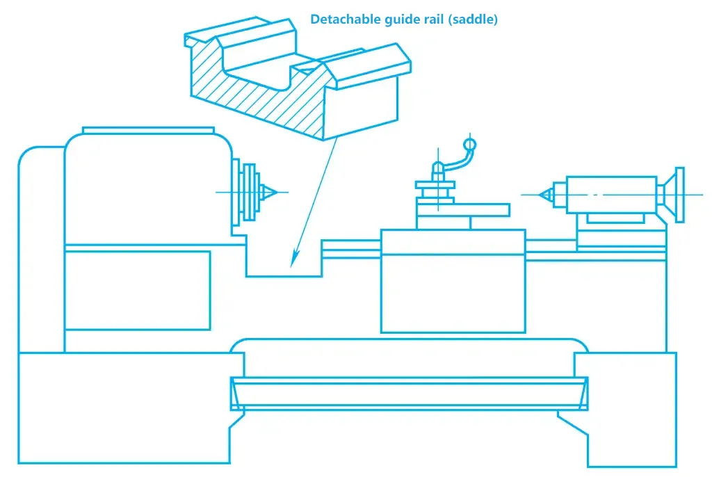
However, due to the frequent mounting and dismounting of the saddle guide rail, its rigidity and working accuracy are reduced. Therefore, this type of machine is mainly used in small factories and repair workshops with fewer equipment and small batch production.
Although the horizontal lathe has greater flexibility and a wider processing range, the square tool post can only hold four tools, and the tailstock can only hold one hole machining tool, relying on manual
movement, tightening the tailstock to the required position, and the tool mounted on the tailstock cannot be fed automatically.
When processing complex parts, especially those with internal holes and internal threads, the need for frequent tool changes, tool setting, tailstock movement, trial cutting, measuring, etc., extends auxiliary time, reduces productivity, increases labor intensity, especially in batch production, these shortcomings are particularly prominent.
The turret lathe is developed based on the horizontal lathe to address the aforementioned deficiencies. The main difference between this type of lathe and the horizontal lathe is the removal of the tailstock and lead screw, and a multi-position turret is installed at the position of the lathe’s tailstock.
Common types of these lathes include the capstan lathe, saddle-type turret lathe, and slide-type turret lathe. Taking the saddle-type turret lathe as an example, this introduces the features and applications of this type of lathe. As shown in Figure 5, in addition to the front tool post 3, the saddle-type turret lathe also has a turret that can rotate around a vertical axis at the rear of the bed, which can perform longitudinal rapid advance, rapid retreat, and working feed along the bed guide rail.
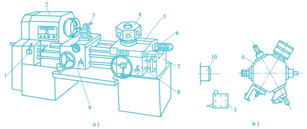
1—Feed box
2—Headstock
3—Front tool post
4—Turret
5—Longitudinal slide
6—Fixed stop device
7—Bed
8—Turret slide box
9—Front tool post slide box
10—Main spindle
The turret tool post is hexagonal, and a turning tool or hole machining tool can be installed on each face with the help of an auxiliary tool, mainly used for machining internal and external cylindrical surfaces. This type of lathe does not have a lead screw and cannot turn threads, but the turret tool post can be equipped with taps and dies for tapping and threading shorter internal and external threads; the front tool post can be fed longitudinally and transversely, for turning large cylindrical surfaces, end faces, grooves, cutting off, etc.
Before machining, the turret lathe requires the tool positions to be adjusted in advance according to the workpiece machining process, as well as the longitudinal and transverse stops on the machine. During machining, after each operation step is completed, the tool post rotates once, and then the next step is performed until completion.
Because the turret lathe is equipped with multiple tools, after the machine is adjusted, it processes in sequence without the need for frequent tool changes, tool setting, or measurement, which greatly improves productivity. It is suitable for batch processing of small, relatively complex rotary workpieces, but the adjustment of stops and tools before machining is time-consuming, limiting its application in single-piece and small-batch production.
In turning machining, general-purpose fixtures are widely used, and many general-purpose fixtures have become lathe accessories, produced in uniform specifications by specialized machine tool accessory factories to meet the needs of users. Main lathe accessories include chucks, dial plates, centers, faceplates, center rests, and follow rests, etc.
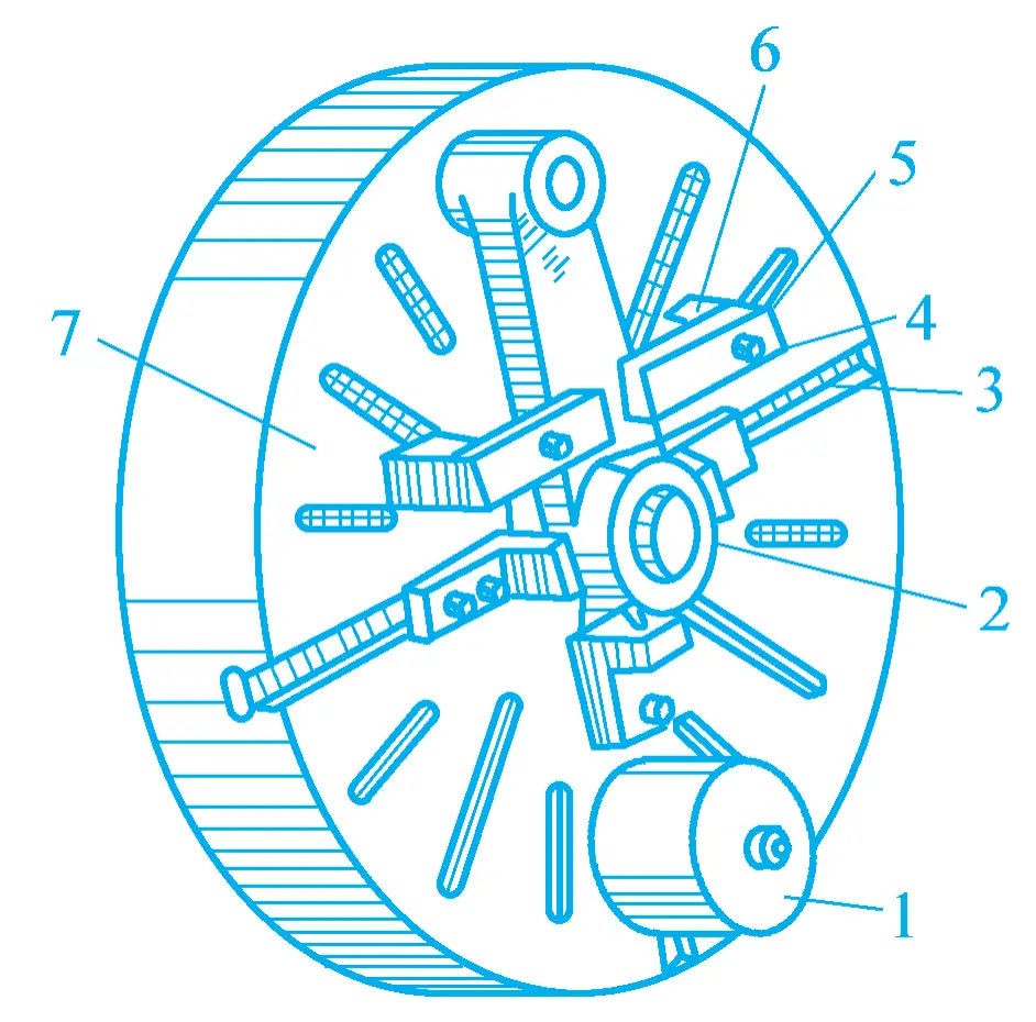
The structure of the three-jaw self-centering chuck is shown in Figure 6, which can be mounted on the main spindle through a flange. Inside the chuck body 6, there is a large bevel gear 3, which meshes with three evenly distributed small bevel gears with wrench holes 5.
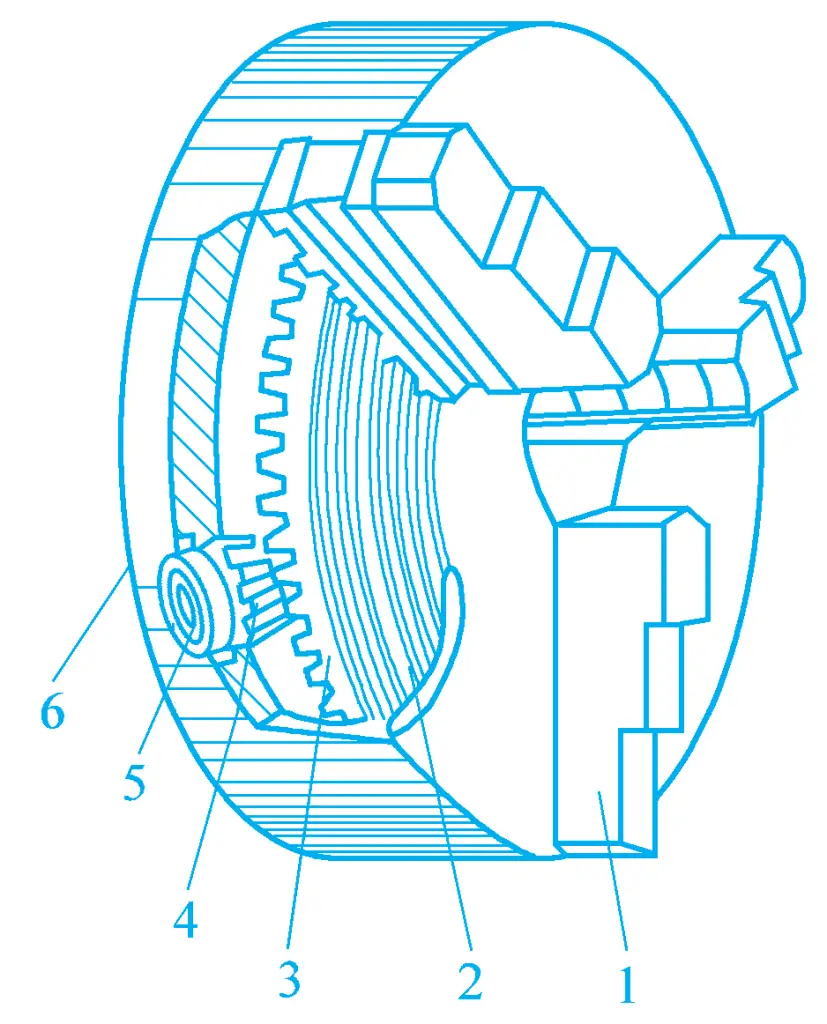
By inserting a wrench into wrench hole 5 to rotate the small bevel gear, the large bevel gear can be driven to rotate, and the flat threads on the back of the large bevel gear 2 mesh with the flat threads on the back of the three jaws 1. As the large bevel gear rotates, the jaws 1 can move radially inward or outward, thereby clamping or releasing the workpiece.
The three-jaw self-centering chuck can automatically center the workpiece without the need for alignment, especially suitable for holding workpieces with circular, equilateral triangular, hexagonal cross-sections, etc. However, the three-jaw self-centering chuck has a small clamping force and does not transmit a large torque, only suitable for clamping medium and small workpieces.
The structure of the four-jaw independent chuck is shown in Figure 7, its four jaws are independent of each other, each jaw’s back has a half-thread internal thread that meshes with a screw, allowing for independent adjustment. Therefore, the four-jaw independent chuck can not only hold workpieces with circular cross-sections but also hold workpieces with square, rectangular, elliptical, and other irregular shapes.
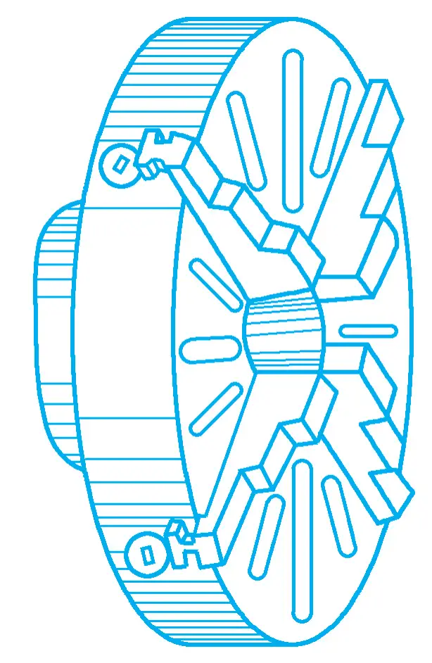
The four-jaw independent chuck has a greater clamping force on the workpiece, and because it cannot automatically center, careful alignment is required when clamping the workpiece. Therefore, it requires a higher skill level from the operator and is used more in single-piece, small-batch production, and large workpiece production.
The faceplate is a large disc mounted on the main spindle, its end face is flat and perpendicular to the spindle axis. If the end face is not flat or not perpendicular to the spindle axis, it can be finely turned on the lathe in use. The end face of the faceplate has many long slots for passing bolts to press the workpiece.
The faceplate is mainly used for machining asymmetric complex workpieces that require parallelism to the reference surface A and perpendicularity of the rotary axis to the base surface A, as shown in Figure 8. The reference surface A can be pre-machined, with the A surface against the faceplate, clamped after aligning the hole position according to the marking, then the hole and the plane parallel to the A surface can be turned.
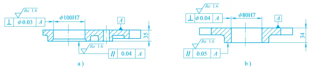
Figure 9 shows the clamping diagram of a connecting rod on the faceplate. The two end faces of the connecting rod are required to be parallel, and the axis of the big end hole is required to be perpendicular to the end face, thus one end face of the connecting rod should be used as the reference and contact the faceplate plane, machining the hole and the other end face. When clamping, an appropriate position should be selected to place the pressing plate to prevent deformation of the workpiece. If the workpiece is biased to one side, a balance block should be placed.
1—Balance block
2—Workpiece
3—Screw slot
4—Screw
5—Pressing plate
6—Shim
7—Faceplate
When the plane to be machined on the workpiece has a perpendicularity requirement relative to the reference surface A, or the axis of the hole or outer circle to be machined has a parallelism requirement relative to the reference surface A (see Figure 10), it can be clamped on the faceplate-bending plate, as shown in Figure 11.
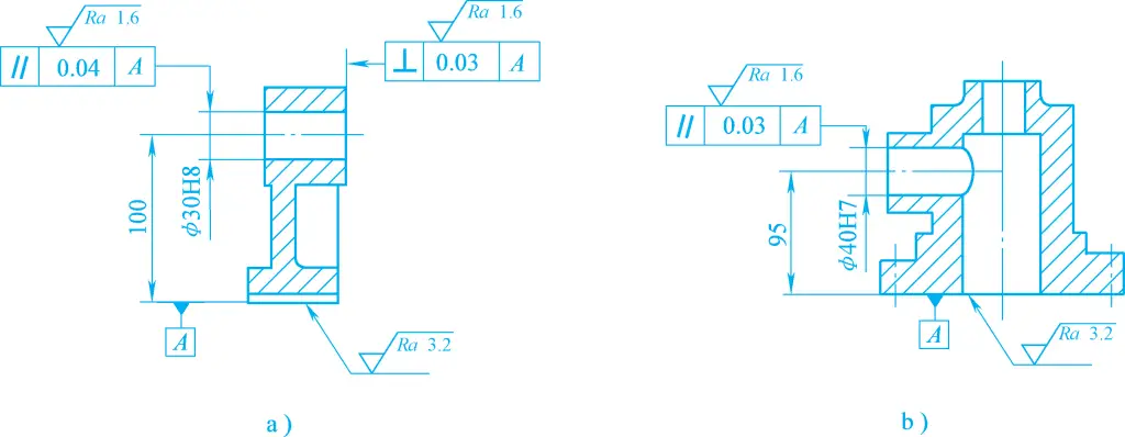
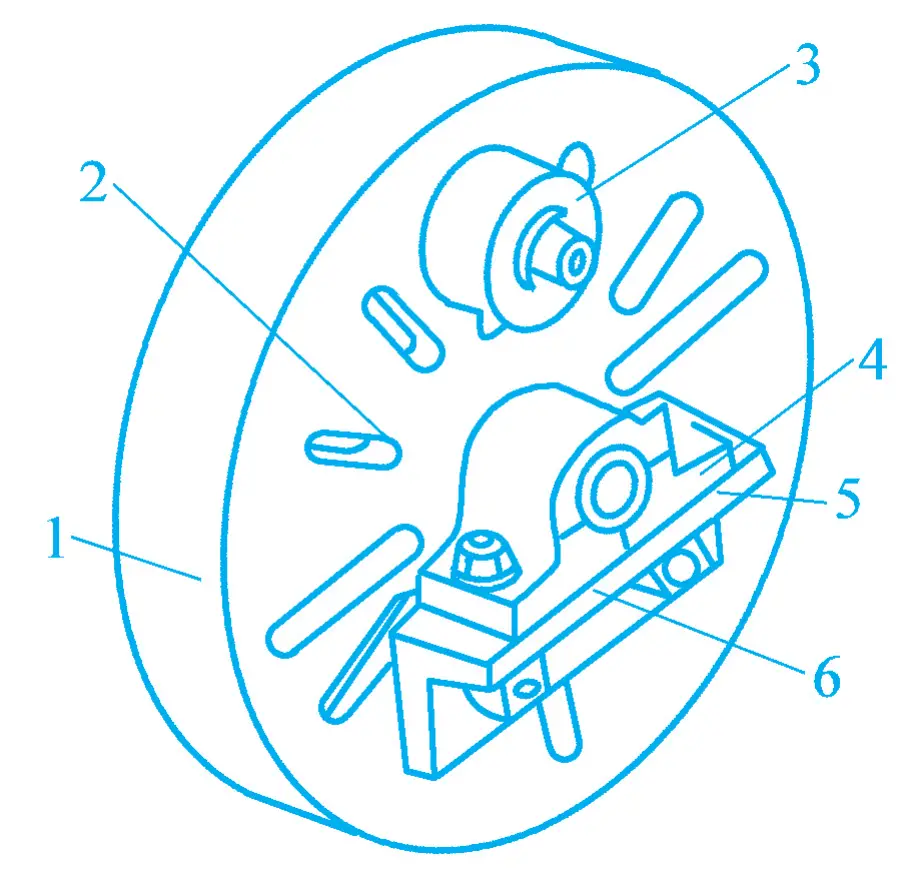
1—Flower disk
2—Screw slot
3—Balance block
4—Workpiece
5—Positioning datum surface
6—Bending plate
When turning shaft-type workpieces, it is common to use centers, collets (one type is also called a chicken heart chuck), and dials to clamp the workpieces, as shown in Figure 12. The center is a frequently used accessory for machining shaft-type workpieces, as shown in Figure 13.
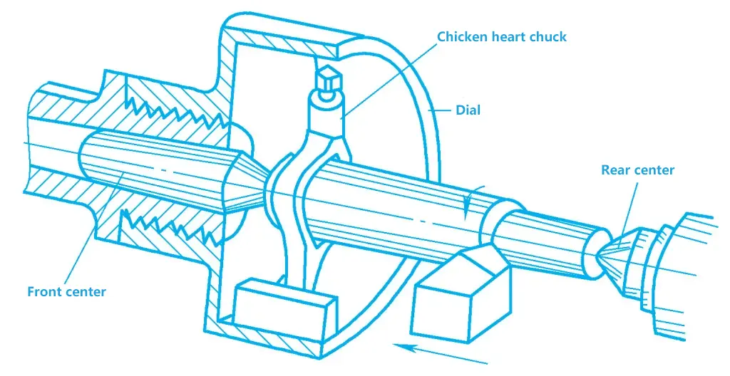
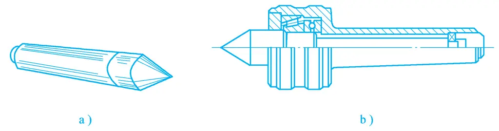
a) Fixed center
b) Live center
The workpiece is supported by the center mounted in the spindle and the center mounted in the tailstock, driven to rotate by the dial and collet. The front center rotates with the spindle, while the rear center rotates with the workpiece, known as the live center. The one that does not rotate with the workpiece is called the fixed center.
The advantage of the fixed center is that it is more accurate in centering, has good rigidity, and clamps the workpiece more stably, but it generates more heat, and the center and center hole may burn out at high speeds, suitable for cutting at lower speeds and high precision requirements. The live center is suitable for high-speed cutting, but the machining accuracy is lower. To clamp the workpiece with a center, a center hole must first be drilled on the end face of the workpiece.
When machining the outer circle and end face of disc sleeve-type workpieces with holes, it is common to mount the workpiece on a mandrel. There are many types of mandrels, commonly used ones include tapered mandrels, cylindrical mandrels, and expandable mandrels, as shown in Figure 14.
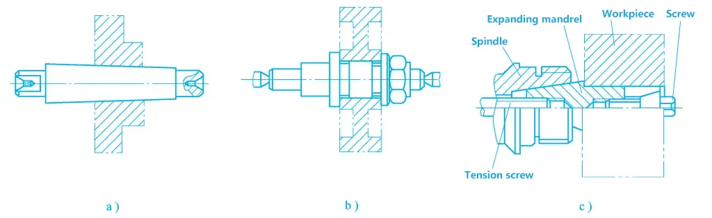
a) Tapered mandrel
b) Cylindrical mandrel
c) Expandable mandrel
The structure of the center rest and follower rest is shown in Figure 15. When turning slender shafts, due to the poor rigidity of the workpiece, bending and vibration occur under the action of its own weight, centrifugal force, and cutting force, making machining difficult, hence the need to use auxiliary clamping mechanisms such as center rests, follower rests, etc.
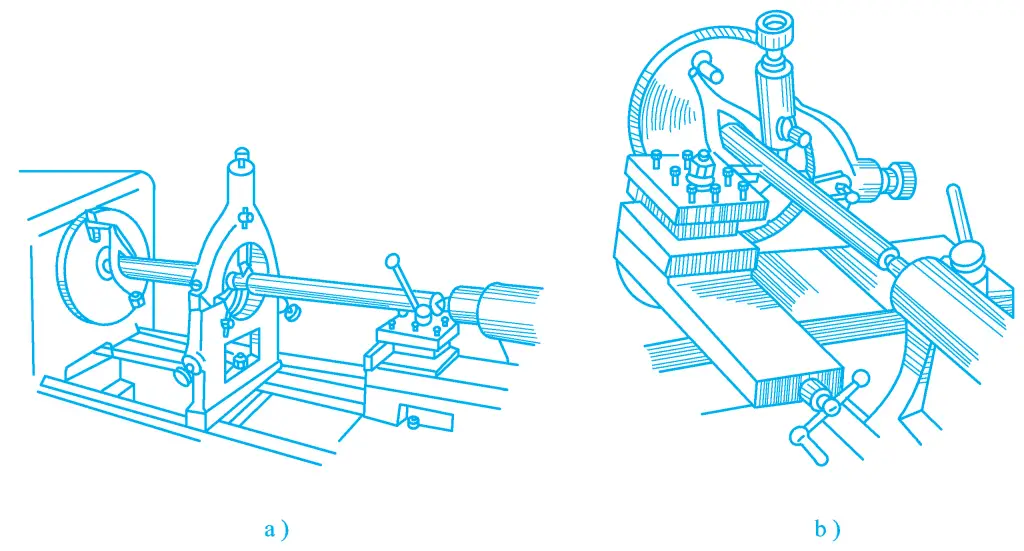
a) Using center rest to turn long shafts
b) Using follower rest to turn long shafts
The bottom of the center rest is fixed on the bed with screws and pressure plates, and its three individually adjustable supporting claws support the workpiece, which are commonly made of cast iron, copper, etc. When the surface of the workpiece is rough, a smooth shaft neck should be turned at the installation position of the supporting claws first.
Using the center rest can effectively improve the support rigidity of slender shafts, thereby improving machining accuracy. The center rest can also be used for machining the end faces of long shafts, long sleeve-type workpieces, as well as boring, cutting off, etc.
The follower rest is fixed on the lathe saddle and moves together with the tool, which is an effective measure to resist radial cutting force and prevent the workpiece from bending and deforming. When rough turning with the follower rest, a section of the outer circle should first be turned on the right end of the workpiece, adjust the tightness of the follower rest’s supporting claws based on the outer circle, place the cutting tool to the left of the supporting claws, and as close to the supporting claws as possible, then turning can be carried out.
When finishing the light shaft, the tool should be placed on the right side of the support claw and as close to the support claw as possible to prevent the support claw from scratching the surface after finishing. When using the center frame and the follower tool holder, the spindle speed should not be too high, and machine oil should be added for lubrication at the support claw.
The tool holder is the most widely used cutting tool in metal cutting processing. It can be used on a lathe to process external circles, end faces, internal holes, chamfering, grooving and cutting off, threading, and forming surfaces, etc.
There are many types of tool holders, which can be divided into external circle tool holders, internal hole tool holders, etc., as shown in Figure 16. According to the structure, they can be divided into integral type tool holders, welded type tool holders, mechanical clamping type tool holders, indexable type tool holders, and forming tool holders, etc., as shown in Figure 17.
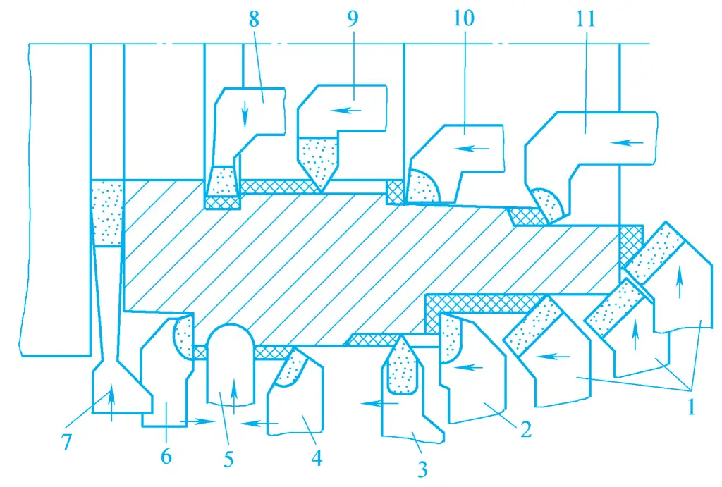
1—45° elbow tool holder
2—90° external circle tool holder (90° right offset tool)
3—External thread tool holder
4—75° external circle tool holder
5—Forming tool holder
6—90° external circle tool holder (90° left offset tool)
7—Grooving tool
8—Internal hole grooving tool
9—Internal thread tool holder
10—Non-through hole tool holder
11—Through-hole tool holder
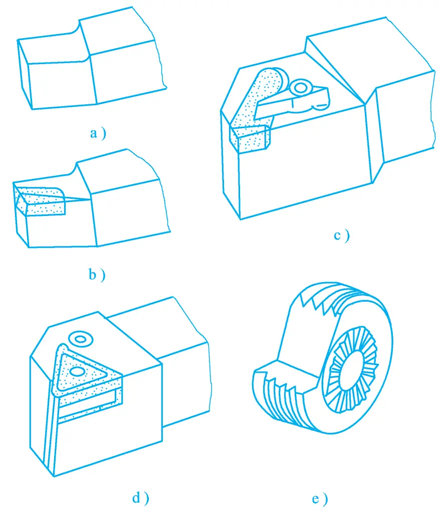
a) Integral type tool holder
b) Welded type tool holder
c) Mechanical clamping type tool holder
d) Indexable type tool holder
e) Forming tool holder
The welded type tool holder is formed by welding a carbide blade onto a structural steel handle. Its advantages are simple structure, convenient manufacturing, good tool rigidity, and flexible use, hence it is still widely used in China.
The mechanical clamping type tool holder does not weld the blade but clamps it onto the handle mechanically, as shown in Figure 18. Carbide mechanical clamping type tool holders are divided into mechanical clamping regrinding type and indexable type.
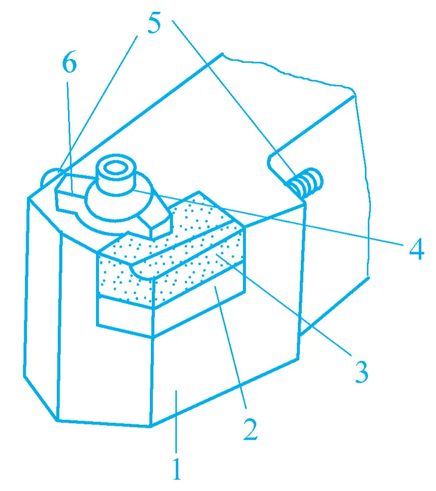
1—Handle
2—Shim
3—Blade
4—Tighten the screw
5—Adjusting screw
6—Pressure plate
The main advantage of this turning tool is that the blade is not subjected to high-temperature welding, avoiding defects such as hardness reduction, cracks, and chipping, thereby improving tool life.
When the cutting edge becomes dull, it is only necessary to remove and grind the blade, and it can be used again after installation. The tool holder can be reused multiple times, and the blades can be ground collectively, ensuring grinding quality, which is beneficial to improving processing quality and efficiency, and also reduces costs. There are many structural forms of clamp-type turning tools.
The indexable turning tool is a turning tool formed by mechanically clamping an indexable carbide (ceramic) insert onto the tool holder. As shown in Figure 19, the indexable carbide (ceramic) inserts used are manufactured by specialized manufacturers, and there are many types of inserts, each with more than three cutting edges for indexing.
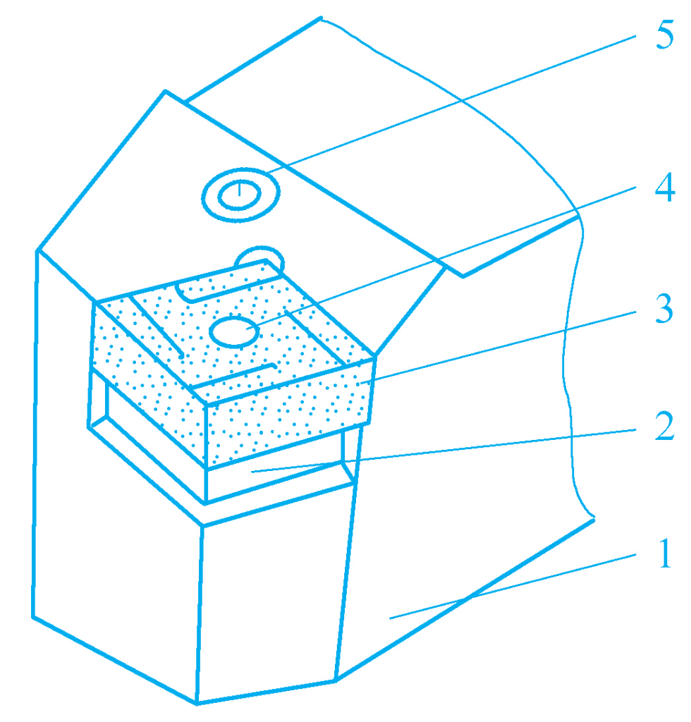
1—Tool holder
2—Shim
3—Insert
4, 5—Clamping elements
When one cutting edge becomes dull, loosen the clamping device, rotate the insert to a new cutting edge, clamp it again, and continue to use it until all cutting edges become dull, then replace with a new insert. The removed insert is not re-ground, so the parameters of the insert are not affected by the level of grinding. This is a tool that is currently being promoted, and you can refer to the national standard GB/T2076—2007 for the types of indexable inserts.
External cylindrical turning is the most basic type of turning work.
90° side tool, 45° bent head turning tool, 75° straight head turning tool are the three basic turning tools for external cylindrical turning.
During turning, the turning tool must be installed correctly to ensure reasonable geometric angles and to bring out the tool’s performance. First, the length of the tool extending from the square tool post should be as short as possible to improve the rigidity of the tool; second, the tip of the tool must be at the same height as the center of the machine spindle, so as to ensure that the front angle and back angle of the tool do not change during work, equal to the grinding angle.
If the tool is installed higher than the center of the machine spindle, it will increase the front angle and decrease the back angle. Sometimes, to improve efficiency during rough turning, the front angle may be increased slightly above the center of the machine spindle. If the tool is installed lower than the center, it will decrease the front angle and increase the back angle. If the tool is installed off-center, it will also change the principal cutting edge angle and the secondary cutting edge angle.
There are several different methods for clamping workpieces when turning external cylinders, each with its own characteristics, advantages, and disadvantages, which should be considered comprehensively based on the size, shape, processing requirements, and production volume of the workpiece.
When selecting a clamping method, the following points should be mainly considered:
1) For irregularly shaped, large-sized single pieces or small batches of raw workpieces, four-jaw independent chucks should be used for clamping. When it is inconvenient to clamp on a four-jaw independent chuck, consider clamping on a faceplate or faceplate bending plate; in medium and above batch production, consider using special fixtures for clamping.
2) For longer shaft or screw-type workpieces that require milling, grinding, etc., after external cylindrical turning, double centers should be used for clamping, with dial plates and live centers to assist in clamping.
3) For heavier long shaft workpieces, when rough turning the external cylinder, one end should be clamped with a chuck and the other end supported by a center.
4) For workpieces that have been machined with an inner hole and require coaxiality with the external cylinder and are short in length, a mandrel can be used for clamping.
5) For turning long shafts with a large length-to-diameter ratio and large cutting volume, or long shafts that need to be turned around, a center rest can be used for clamping.
6) For fine turning of slender shafts with a small amount of cutting allowance and where turning around is not allowed, a follow rest can be used for clamping.
1) External cylindrical turning can be divided into rough turning, semi-finish turning, and finish turning. Before starting the turning, it should first be determined the allowances for rough turning, semi-finish turning, and finish turning.
2) During rough turning, the performance of the tool and the machine should be fully utilized, and the back cutting depth should be as large as possible to complete the rough machining allowance in one working stroke. For forged or cast external cylinders, because the surface is harder or has sand molds, to avoid tool wear, chamfer the workpiece first, then choose a larger back cutting depth for turning.
3) In finish turning, use the trial cutting method to control the size. When turning, it is difficult to ensure accuracy by relying solely on the scales on the dial to determine the back cutting depth. In single-piece and small-batch production, the trial cutting method is a common way to obtain dimensional accuracy. During finish turning, high-speed finish turning with cemented carbide tools or low-speed finish turning with high-speed steel wide-blade tools can be used.
4) Workpieces that need to be tempered or normalized after rough turning should consider the impact of heat treatment deformation on the workpiece, and a margin of 1.5~2.5mm should be left.
5) Workpieces that require grinding do not need to be finish turned, and a grinding allowance can be left during semi-finish turning. In single-piece and small-batch production, for workpieces that only need finish turning, if the surface roughness does not meet the requirements, it can be appropriately polished with emery cloth or a file.
6) Before starting external cylindrical turning, the end face should be turned first to determine the size in the length direction during machining.
7) When turning a stepped shaft, the larger diameter external cylinder should be machined first, then the smaller diameter external cylinder, to ensure the rigidity of the workpiece.
Turning of conical surfaces is a relatively difficult task, which requires not only dimensional accuracy, geometric accuracy, and surface roughness but also angle or taper accuracy. For conical surfaces with high requirements, a conical gauge should be used for the coloring method inspection to evaluate its accuracy based on the size and contact area of the surface.
The following three methods are commonly used for machining conical surfaces on a lathe.
As shown in Figure 20, when the conical angle of the internal and external conical surfaces is α, repositioning the small tool post by α/2 can achieve machining. This method is simple to operate and can machine internal and external conical surfaces of any cone angle. However, it can only be manually fed and is suitable for machining short lengths.
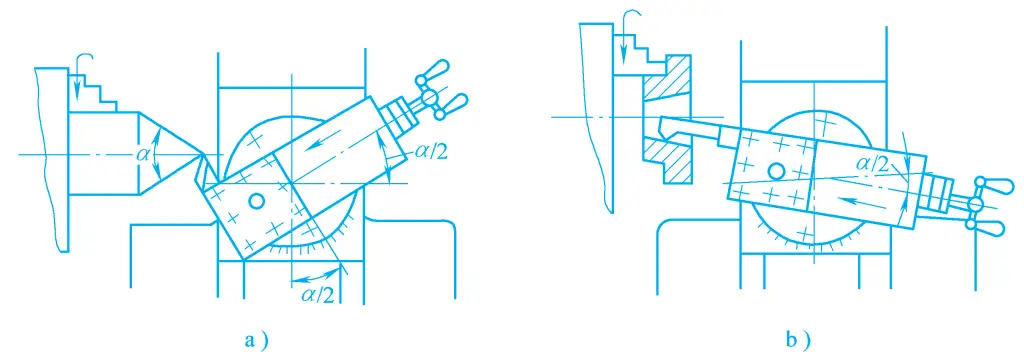
a) Machining external conical surfaces
b) Machining internal conical surfaces
Since the rotation angle of the small slide board cannot be so accurate, the turning of the conical surface is done by measuring while turning and adjusting the angle of the small slide board. For external cones, ring gauges and universal angle rulers can be used for inspection, and for internal cones, plug gauges and the coloring method can be used for inspection.
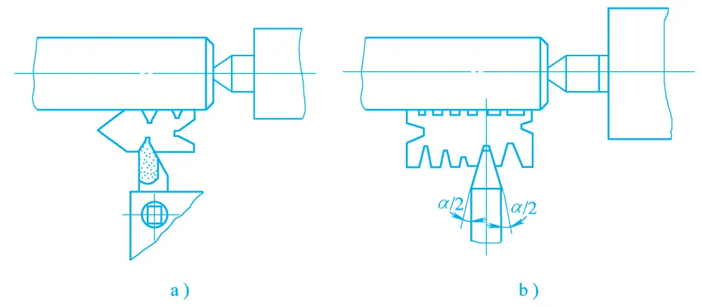
The tailstock offset method, as shown in Figure 21, can only machine the external conical surfaces of shaft-type workpieces or disc sleeve-type workpieces mounted on a mandrel.
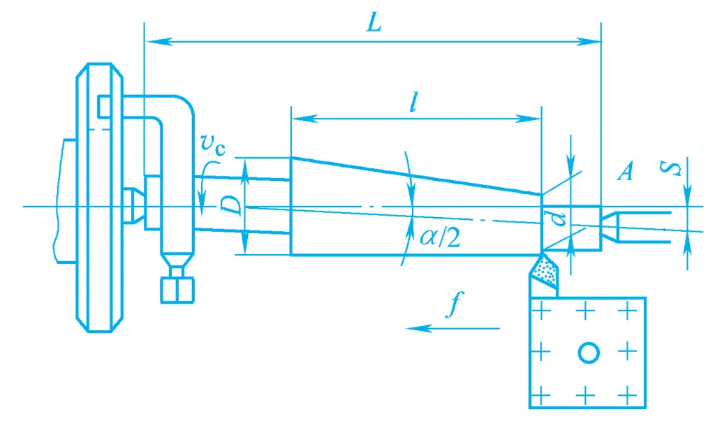
The workpiece or mandrel is clamped between the front and rear centers, and the rear center is offset forward or backward by a certain distance S, making the rotation axis of the workpiece form an angle equal to half the cone angle α/2 with the lathe’s main spindle axis, thus allowing for automatic feed turning. This method is suitable for machining workpieces with longer lengths, smaller tapers, and lower precision requirements.
The template method is a way to turn conical surfaces using a template device. The advantage of the template method is that it is both convenient and accurate, with good center hole contact and high quality. It allows for power feed turning of external conical surfaces, with a bevel angle generally below 12°, suitable for batch production. Due to the widespread use of CNC lathes, the template method for turning conical surfaces is rarely used.
Turning threads is a common method of thread processing. Although there are many types of threads, the processing principles are the same.
1) Grinding of the triangular thread turning tool
The tip angle of a common thread turning tool should be 60°, the tip angle of an imperial triangular thread turning tool should be 55°, the tool’s rake angle γ p should be zero degrees, and the relief angles on both sides should be different due to the influence of the thread helix angle, but can be the same for threads with small pitches.
When turning threads with high-speed steel tools at low speeds, a small lead angle makes it difficult to achieve a smooth thread surface. When using a rake angle γ p =5°~15°, machining is very smooth, but since the cutting edge does not pass through the workpiece axis, the thread profile is not a straight line but a curve. This error can be disregarded for threads with low requirements, but a larger lead angle significantly affects the tip angle.
When γ p =10°~15°, the tip angle of the turning tool should be reduced by 40′~1°40’. For threads with high precision, the rake angle γ p of high-speed steel turning tools should be 0°~5°, and for cemented carbide turning tools, γ p should be 0°.
Cemented carbide turning tools are suitable for high-speed cutting of threads. During turning, the tooth profile angle of the workpiece will increase, therefore, the tip angle should be reduced by 30’. When turning threads with higher hardness, grind a negative chamfer of 0.2~0.4mm wide on the two cutting edges, with its γ o1 =-5°. Whether the grinding is correct can be checked with a template.
2) Grinding of rectangular and trapezoidal thread tools
When turning threads, due to the influence of the feed motion, the position of the cutting plane and the base plane changes, making the front angle and back angle of the tool during work different from the front angle and back angle of the ground tool. The degree of change depends on the size of the thread lead angle. Rectangular threads, trapezoidal threads, and multi-start threads often have a large lead, and a larger helix angle, therefore, this issue should be taken into account when grinding.
The change of the back angle on both sides of the turning tool. The working back angle on both sides of the turning tool is generally taken as 3°~5°, as shown in Figure 22. When turning right-hand threads, due to the inclination of the cutting plane, the working back angle on the left side will decrease by the thread lead angle φ, making the turning tool unable to work normally.
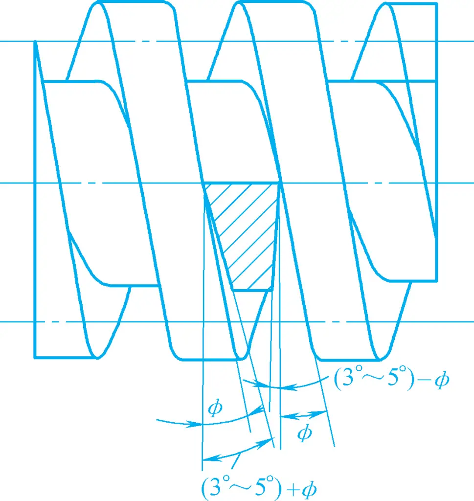
Therefore, the ground back angle α oL on the left side should equal the working back angle plus the thread lead angle φ. To ensure the strength of the turning tool, the ground back angle α oR on the right side should equal the working back angle minus the thread lead angle φ. When turning left-hand threads, the situation is reversed.
αoL=(3°~5°)+ φ
αoR = (3° ~ 5°) – φ
The change of the front angle on both sides of the turning tool. Due to the change in the position of the base plane, the working front angle on both sides of the turning tool becomes unequal to the ground front angle (see Figure 23). If turning right-hand threads, the ground front angle on both sides of the tool is 0°, then the working front angle γ oeR on the right side becomes negative, making cutting difficult.
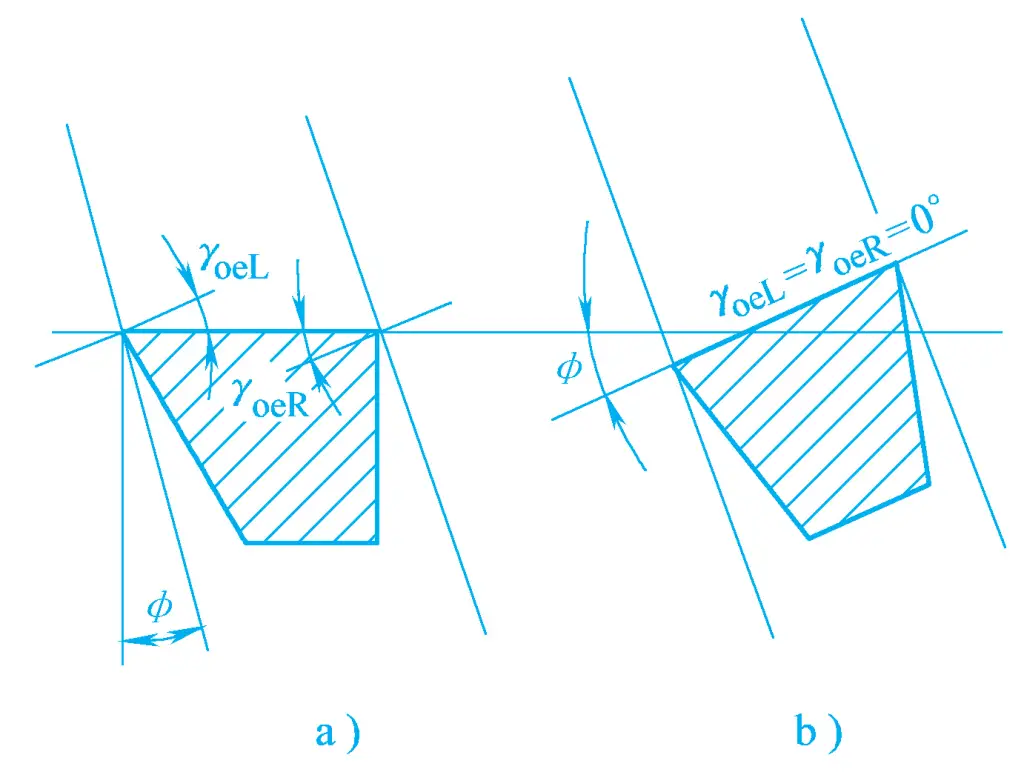
a) Horizontal installation of the tool
b) Normal installation of the tool
To improve the cutting state, the front face of the tool is clamped perpendicular to the helix line, that is, normal installation, then the working front angles on both sides of the tool are equal, γ oeL =γ oeR =0°; the tool can also be installed horizontally, and large chip flutes are ground on both sides of the front face to increase the front angle, making the machining smooth.
When installing the thread turning tool, the tip of the tool must be at the same height as the thread axis of the workpiece, and the bisector of the tool tip angle must be perpendicular to the axis of the workpiece, to ensure the correctness of the thread profile. Thread turning tools often use templates to find the correct position of the tool for installation, as shown in Figure 24.
a) Turning triangular threads
b) Turning trapezoidal threads
1) Direct feed method
During turning, after each reciprocating stroke, the tool is fed laterally. Through multiple reciprocations and lateral feeding, the thread is turned well. This method cuts both sides simultaneously during turning, which is prone to tool jamming, hence it is often used for cutting small pitch triangular threads.
2) Left and right cutting method
During the turning process, in addition to lateral feeding, the small slide is also used to feed the tool slightly to the left or right. Repeating this several times turns the thread well. This method allows the tool to cut with a single edge, improving the force distribution, and can achieve a surface with a smaller roughness value.
For rough turning, for convenience, the small slide can move in one direction, while for finish turning, the small slide must move left and right alternately to polish both sides. The last one or two cuts of finish turning can use the direct feed method to ensure the correctness of the tooth profile.
Generally, thread machining requires multiple passes to complete. If the tip of the tool does not align with the thread groove cut in the previous pass, but is offset to the left or right, it will result in cross threading. This phenomenon is called cross threading.
The main cause of cross threading is when the lead screw turns once, but the workpiece does not complete a full turn. When threading, both the workpiece and the lead screw are rotating. After lifting the half nut, one must wait for the lead screw to complete a turn before pressing it down again. When the lead screw has turned once and the workpiece has turned a full turn, the tool can enter the previously cut spiral groove without causing cross threading. If the workpiece has not turned a full turn after the lead screw has turned once, cross threading will occur.
According to the above principle, cross threading will not occur when P 丝 /P 工 equals an integer, and will occur when it is not an integer. On the CA6140 lathe, threading imperial and module threads also results in cross threading. When threading without cross threading, one can open the half nut to retract the tool.
To prevent cross threading, do not arbitrarily open or close the half nut during the machining process, but use the method of forward and reverse turning, that is, keep the half nut closed at the end of the first pass, retract the tool radially, then reverse the main spindle, retract the tool longitudinally, and then proceed to the next cut.
In this way, because the transmission between the main spindle, lead screw, and tool post has never been disconnected during the reciprocating process, cross threading will not occur.
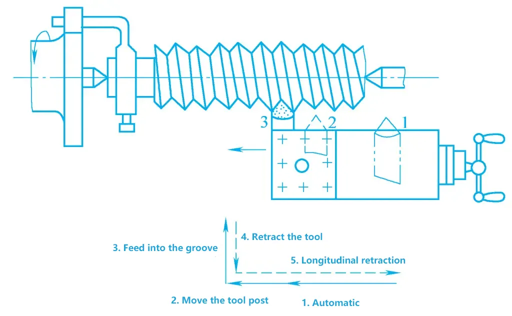
During the turning process, after changing or grinding the tool, it should be realigned (see Figure 25), first close the half nut, position the tool at position 1, start the machine and move the tool post forward a distance to position the tool at position 2, to eliminate the gap between the lead screw and the nut, then turn the small slide and the middle slide to drop the tool into the original thread groove, position the tool at position 3, retract the tool laterally, then move the tool to a few millimeters outside the right end face of the workpiece, to continue turning.
Ordinary threads are machined with high-speed steel tools, which can only use relatively low cutting speeds, and the number of reciprocating work strokes is high. For example, for turning a thread with a pitch of 2mm, at least 12 reciprocating work strokes are generally required. However, using carbide turning tools, very high cutting speeds can be adopted, with fewer reciprocating work strokes, thus greatly improving productivity and machining quality. The specific methods are as follows:
Use carbide turning tools with cutting speeds of 50~100m/min, feed the tool directly, and it is ideal for the chips to be expelled vertically to the axis or in a spherical shape. When cutting, do not use the left and right feeding method, as this will pull the thread surface on the other side.
When high-speed cutting external threads, the compression of the turning tool will cause the radial dimension of the thread to expand. Therefore, the outer diameter before turning the thread should be smaller than the major diameter of the thread. For medium carbon steel, turning metric threads with a pitch of 1.5~3.5mm, the outer diameter can be 0.2~0.4mm smaller.
When high-speed cutting internal threads, the hole diameter before turning the internal thread should be somewhat larger than the minor diameter of the internal thread, and can be approximately calculated by the following formula:
For ductile metals D hole ≈D-P
For brittle metals Dhole ≈D-1.05P
Where
To ensure the machining of qualified parts, the tooth height formula h 1 =0.5413P should be used to calculate the tooth height, and allocate the amount of back cutting for each time. Start with a larger value during rough turning, generally around 0.2~0.3mm, and take 0.1~0.15mm during finish turning.
To machine a thread with a pitch of 1.5mm, only 3~5 reciprocating work strokes are required to complete the machining. For larger pitches, more cutting passes are taken, and the amount of back cutting for the last finish turning cannot be less than 0.1mm, after which the workpiece can be inspected with measuring tools.