CNC Lathe Components: Essential Mechanisms Explained
Have you ever wondered what makes a CNC lathe so efficient? This article uncovers the vital components of a CNC…
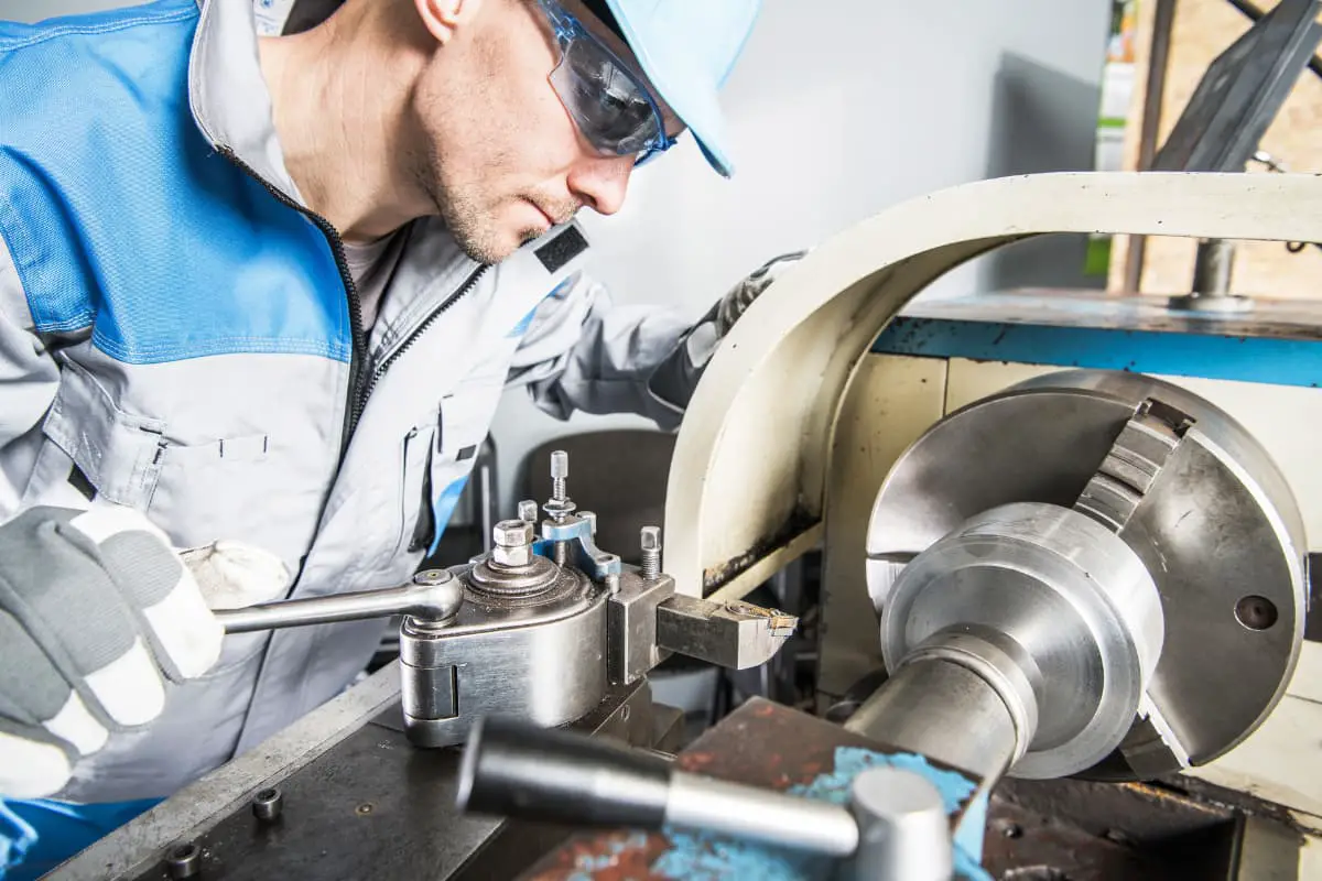
Have you ever wondered how the metal parts that surround us are made? From the tiniest screws to massive machine components, many metal objects are crafted through the art of turning. In this blog post, we’ll explore the fascinating world of lathe operation and the skills needed to shape metal with precision. Whether you’re a curious learner or an aspiring machinist, join us as we uncover the secrets behind this essential manufacturing process.

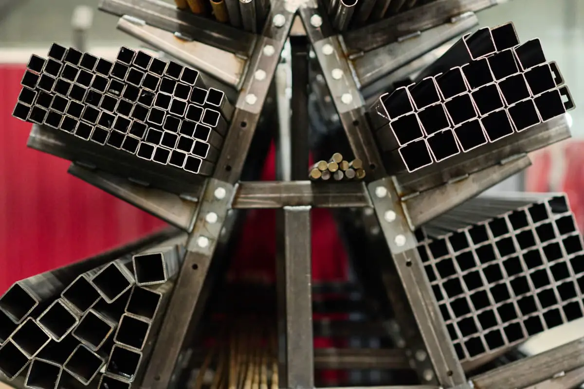
In the mechanical manufacturing industry, complex machines are mostly composed of various types of shafts, sleeves, discs, threads, cones, and irregular parts, all of which need to be completed through rough and fine machining by lathe operators.
With the development of technology, although some parts are made through precision casting and cold working, most still cannot do without metal cutting processing. Especially for parts with high precision requirements, they still need to be machined through turning and grinding.
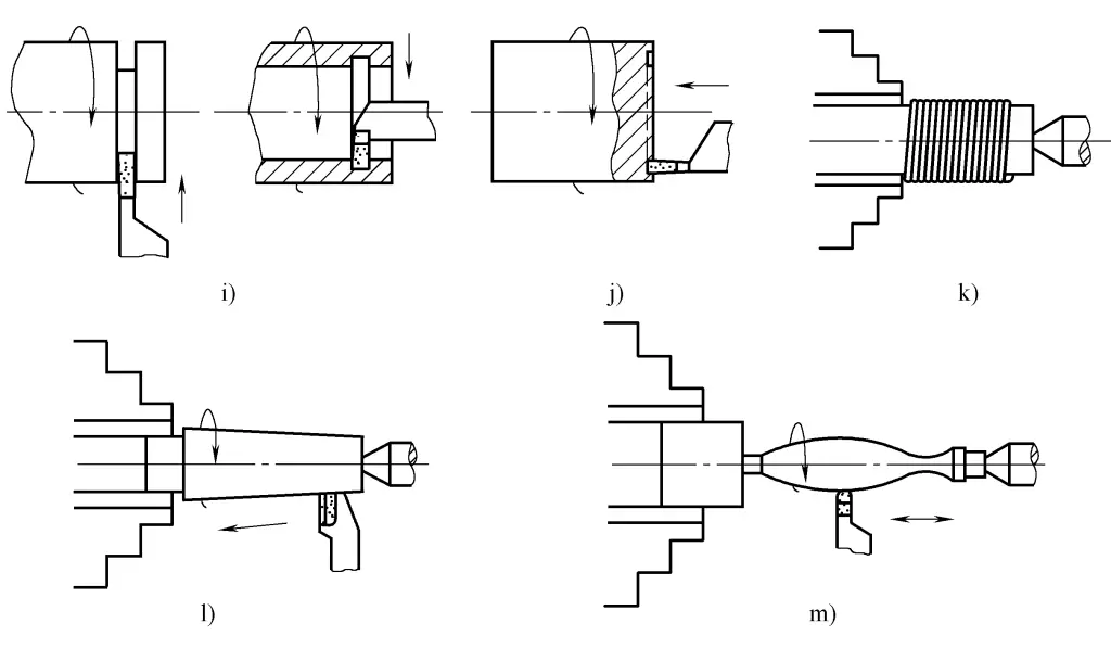
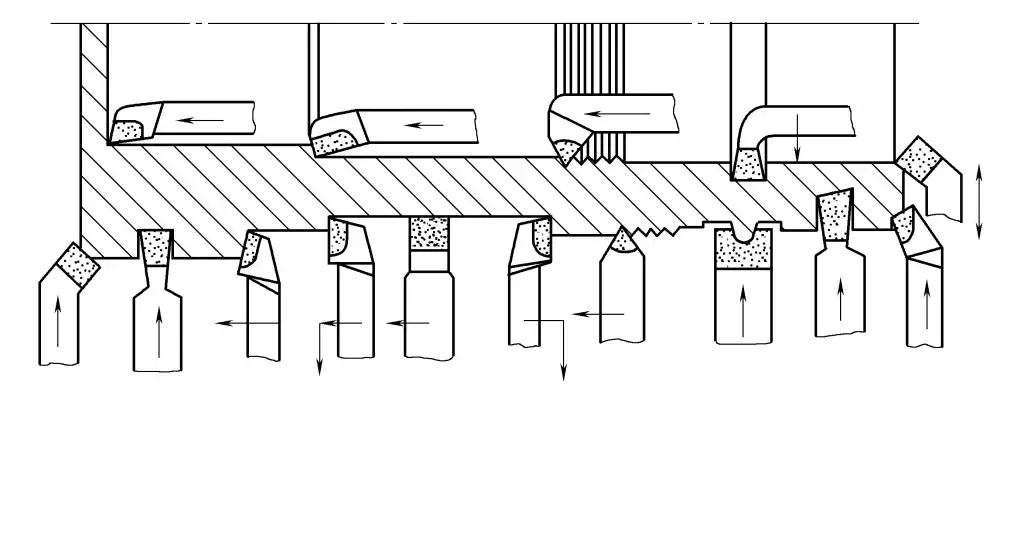
The scope of turning operations includes: turning external cylinders, facing, boring internal holes, cutting external threads, cutting internal threads, drilling center holes, drilling, knurling, parting or cutting external/internal grooves, facing grooves, winding springs, turning external tapers, and forming surfaces, as shown in Figure 1.
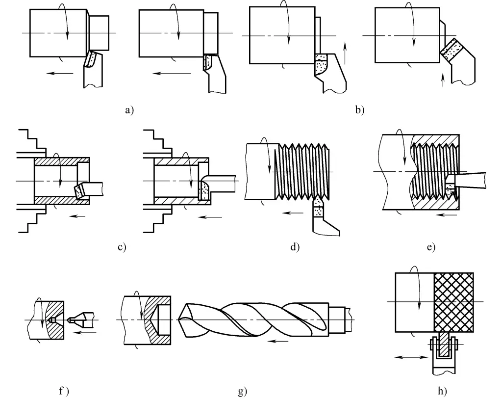
a) Turning external cylinder
b) Facing
c) Boring internal hole
d) Cutting external thread
e) Cutting internal thread
f) Drilling center hole
g) Drilling
h) Knurling
i) Parting or cutting external/internal groove
j) Facing groove
k) Winding spring
l) Turning external taper
m) Forming surface
In metal cutting processing, the workpiece is the general term for the object being processed in the machining process. Any workpiece must go through the process from raw material to finished product.
In this process, to perform cutting operations on the workpiece with the tool to form various surfaces, there must be relative motion between the tool and the workpiece. This relative motion in metal cutting processing is called cutting motion. Cutting motion can be divided into main motion and feed motion according to its function.
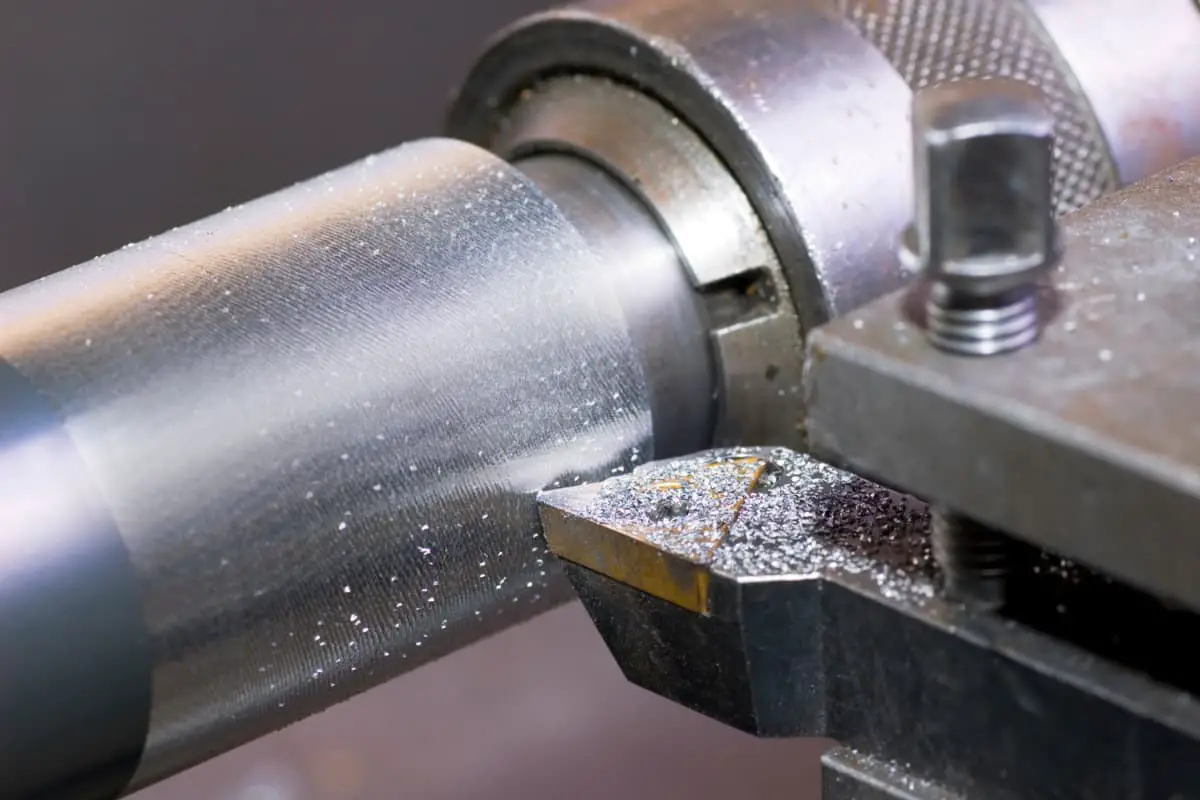
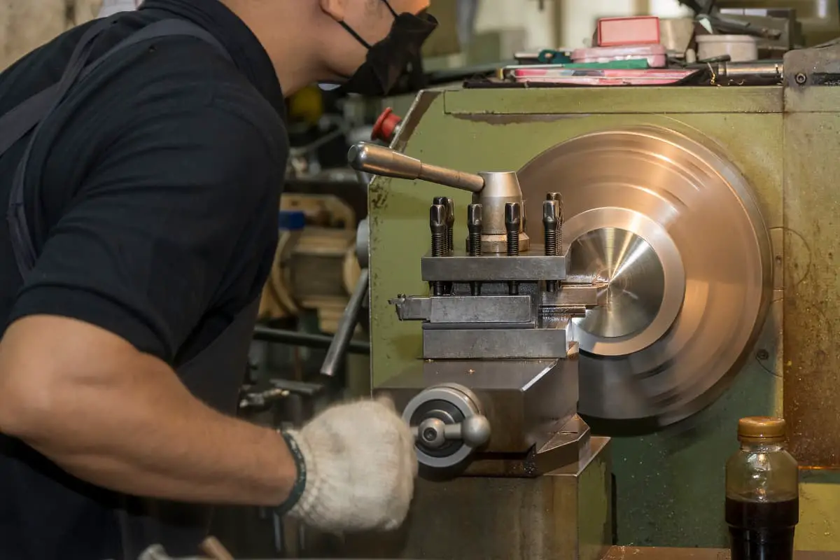
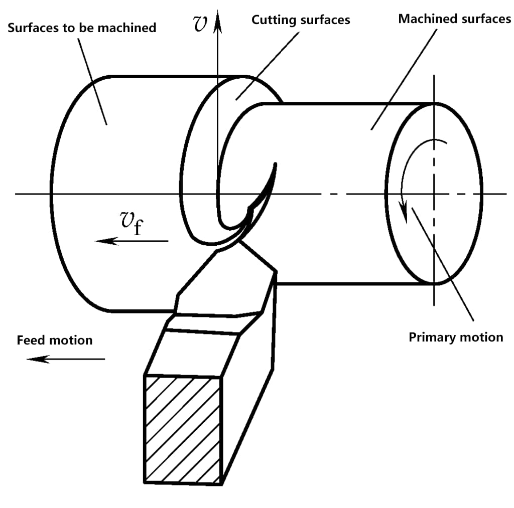
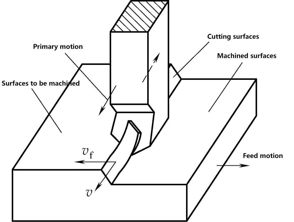
The main motion is the movement necessary to remove excess metal layers from the workpiece and form new surfaces. It is the most basic and important movement in cutting operations, usually with the highest speed and consuming the most machine power. Examples include the rotational movement of the workpiece in turning operations (Figure 2), the rotational movement of the tool in milling, boring, and drilling operations, and the linear movement of the planer tool in planing operations (Figure 3).
Feed motion is a movement that intermittently or continuously introduces the metal layer to be cut into the cutting process. In combination with the main motion, it continuously removes metal layers to obtain the desired surface.
The characteristics of feed motion are low speed and low power consumption. It can consist of one or more movements. In external cylindrical turning, the longitudinal feed motion along the workpiece axis is continuous, while the transverse feed motion along the workpiece diameter is intermittent.
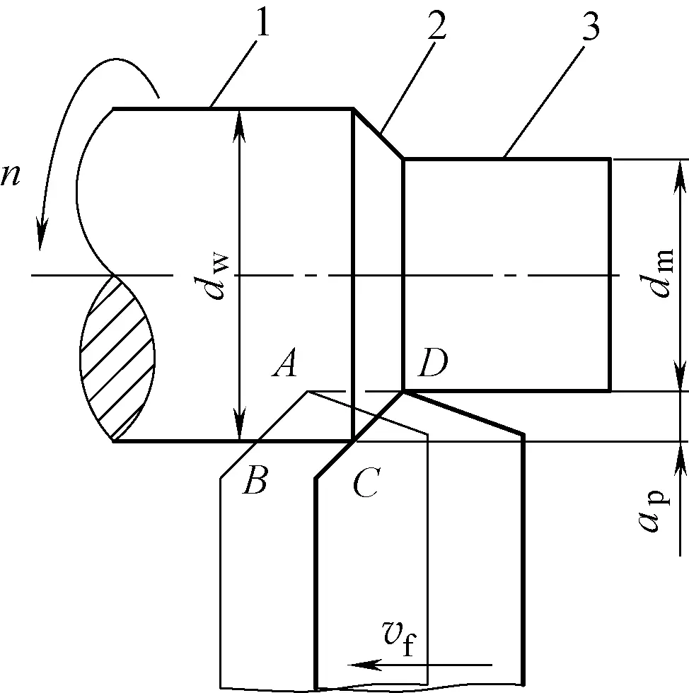
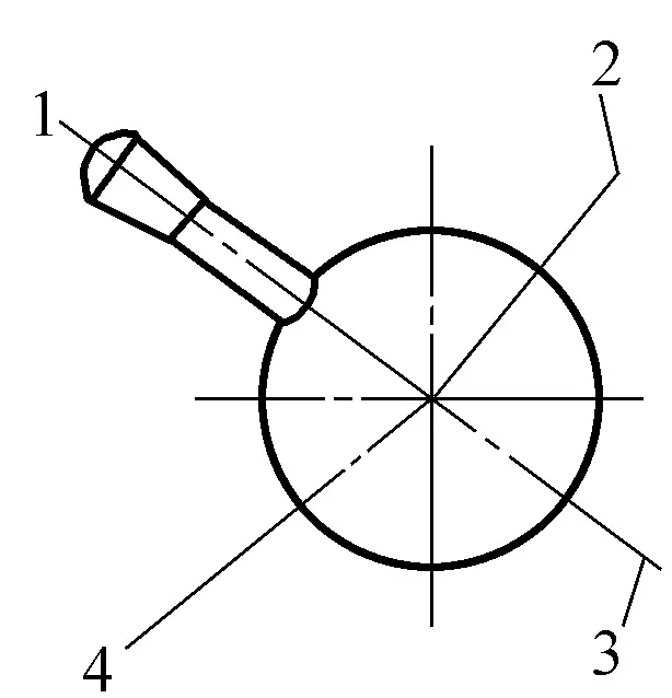
Three surfaces are formed on the workpiece during the cutting process. The surface to be machined refers to the surface on the workpiece that is about to be cut off, i.e., surface 1 in Figure 4. The transition surface is the surface on the workpiece that the cutting edge is currently cutting, such as surface 2 in Figure 4. The machined surface refers to the surface formed on the workpiece after cutting, such as surface 3 in Figure 4.
Cutting parameters are used to measure the magnitude of cutting motion. Cutting speed, feed rate, and depth of cut are known as the three elements of cutting parameters. Only by reasonably determining the cutting parameters can cutting be carried out smoothly, which is also an effective way to ensure product quality and improve labor productivity.
The depth of cut is the contact length between the cutting edge of the tool and the cutting surface of the workpiece measured in the working plane perpendicular to the direction of the main motion and feed motion. For external cylindrical turning, the depth of cut is the vertical distance between the machined surface and the surface to be machined on the workpiece, measured in mm. That is
ap=1/2(dw-dm)
In the formula
The feed rate is the displacement of the tool relative to the workpiece in the direction of the feed motion. Different machining methods, due to the different tools used and forms of cutting motion, have different expressions and measurement methods for feed rate.
The unit of feed rate is mm/r (used for turning, boring, etc.) or mm/stroke (used for planing, grinding, etc.). Feed rate indicates the speed of the feed motion. The speed of feed motion can also be expressed as feed speed vf (unit is mm/s) or feed per tooth f z (used for multi-tooth tools such as milling cutters and reamers, unit is mm/z). Generally
vf=nf-dzfz
In the formula
The cutting speed is the speed of the selected point on the cutting edge of the tool relative to the workpiece’s main motion, measured in m/min or m/s. Since the cutting speed at different points on the cutting edge is different, the maximum cutting speed is often used to represent the cutting speed of the tool in calculations. The formula for calculating the cutting speed when turning an external cylinder with a lathe tool is
v=πdwn/1000
In the formula
In milling, since the milling cutter is a multi-tooth tool, the feed rate unit is specified as feed per tooth in addition to mm/r, denoted as a f , with a unit of mm/z. The relationship between v, f, and a f is
vf=nf=nafz
Where z is the number of teeth on the multi-tooth tool.
In summary, in actual production, the workpiece diameter is usually known, and the cutting speed is determined based on factors such as workpiece material, tool material, and machining characteristics. Then, the cutting speed is converted to lathe speed for machine adjustment. Try to choose a speed that matches the speeds listed on the lathe’s nameplate.
Reasonable selection of cutting parameters can ensure workpiece machining quality, improve cutting efficiency, extend tool life, and reduce processing costs. According to the requirements of different machining characteristics for cutting operations, cutting parameters will be selected differently.
For rough machining, the priority should be to ensure a high metal removal rate and necessary tool life. Generally, a large depth of cut is selected first, followed by a relatively large feed rate, and finally, an appropriate cutting speed is determined based on tool life.
For finish machining, the workpiece’s machining quality should be ensured. Generally, a smaller feed rate and depth of cut are selected, with the highest possible cutting speed.
The depth of cut for rough machining should be determined based on the machining allowance of the workpiece, aiming to remove the entire allowance in one pass if possible. When the machining allowance is too large, machine power is insufficient, the rigidity of the technological system is low, tool strength is inadequate, or there is intermittent cutting or significant impact vibration, multiple passes may be necessary.
For cast or forged parts with a hard surface layer, the depth of cut should be greater than the thickness of the hard layer to protect the tool tip. Semi-finishing allowance (1-3mm) and finishing allowance (0.1-0.5mm) can be removed in one pass. The depth of cut for semi-finishing and finishing is determined by the allowance left after rough machining, based on the required machining accuracy and surface roughness.
When cutting with carbide turning tools, since the cutting edge is not easily sharpened on a grinding wheel, the depth of cut for the final pass should not be too small, preferably a p =0.1mm, otherwise it will be difficult to achieve the required surface roughness of the workpiece. If using indexable turning tools, the allowance for finish machining should be determined based on the nose radius R of the insert.
For rough machining, the selection of feed rate is mainly limited by cutting force. When the rigidity and strength of the technological system are good, a larger feed rate can be selected. For semi-finishing and finishing, since the feed rate greatly affects the surface roughness of the machined workpiece, the feed rate is generally set smaller.
Usually, a reasonable feed rate is selected based on the surface roughness requirements of the workpiece, considering factors such as workpiece material, tool nose radius, cutting speed, and other conditions. When the cutting speed is increased, the tool nose radius is larger, or the tool is ground with a wiper edge, a larger feed rate can be chosen to improve productivity.
After determining the depth of cut and feed rate, an appropriate cutting speed can be determined under the condition of ensuring reasonable tool life. During rough machining, both depth of cut and feed rate are large, and cutting speed is limited by tool life and machine power, generally lower.
For finish machining, both depth of cut and feed rate are set smaller, and cutting speed is mainly limited by workpiece machining quality and tool life, generally set higher. When selecting cutting speed, factors such as the machinability of the workpiece material should also be considered.
For example: The cutting speed for machining alloy steel, high manganese steel, stainless steel, cast iron, etc., should be 20% to 30% lower than that for ordinary medium carbon steel. When machining non-ferrous metals, it should be increased by 1 to 3 times. For intermittent cutting and machining large parts, slender parts, or thin-walled parts, a lower cutting speed should be selected.
When cutting with carbide turning tools, generally higher cutting speeds (80-100m/min) are used. When cutting with high-speed steel turning tools, lower cutting speeds are preferred.
Turning tools can be classified according to their uses into external turning tools, facing tools, parting tools, form tools, threading tools, and boring tools, as shown in Figure 5.
Since turning tools are composed of a tool head and tool body, they can also be classified according to their structure into solid tools, brazed tools, mechanically clamped tools, indexable insert tools, and form tools, as shown in Figure 6.
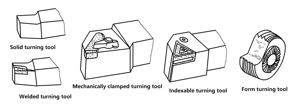
The basic uses of common turning tools are as follows:
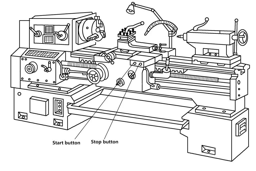
The following items should be carefully checked before starting and operating the machine:
The lathe spindle speed change is controlled by changing the position of two nested handles on the right front of the headstock. The front handle has 6 gears, each gear has 4 speed levels controlled by the rear handle, so the spindle has a total of 24 speed levels, as shown in Figure 8.
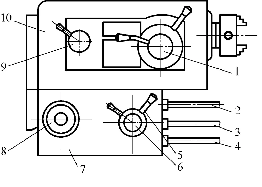
1—Spindle speed change nested handles
2—Lead screw
3—Feed rod
4—Control lever
5—Feed speed change handle
6—Lead screw and feed rod change handle
7—Feed box
8—Feed speed change handwheel
9—Thread direction change handle
10—Headstock
The handle on the left front of the headstock is used for changing between left and right-hand threads and increasing thread pitch. It has 4 positions: right-hand thread, left-hand thread, right-hand increased pitch thread, and left-hand increased pitch thread, as shown in Figure 9.
1—Right-hand thread
2—Left-hand thread
3—Left-hand increased pitch thread
4—Right-hand increased pitch thread
The CA6140 lathe feed box has a handwheel on the left front with 8 positions; on the right side, there are two nested handles, the front handle is for changing between lead screw and feed rod, and the rear handle has positions I, II, III, IV which work with the handwheel to adjust thread pitch or feed rate.
To adjust the required thread pitch or feed rate according to machining requirements, you can refer to the configuration table on the feed box oil tank cover to determine the specific position of the handwheel handle.
The carriage assembly includes the apron, saddle, cross slide, compound rest, and tool post, as shown in Figure 10.
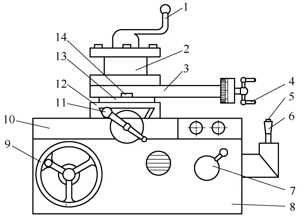
1—Tool post handle
2—Tool post
3—Compound rest
4—Compound rest handle
5—Rapid traverse button
6—Automatic feed handle
7—Half nut lever
8—Apron
9—Large handwheel
10—Saddle
11—Cross slide handwheel
12—Cross slide
13—Graduated dial
14—Lock nut
The carriage assembly performs most of the feed movements during turning: the saddle and apron move longitudinally, the cross slide moves transversely, and the compound rest can move longitudinally or at an angle. There are two types of feed movements: manual feed and power feed.
1) The longitudinal movement of the saddle and apron is controlled by the large handwheel on the left front of the apron.
When turning the handwheel clockwise, the saddle and apron move to the right; when turning counterclockwise, they move to the left. The graduated dial on the handwheel axis is divided into 300 divisions, and for each division the handwheel turns, the saddle and apron move 1mm longitudinally.
2) The transverse movement of the cross slide is controlled by the cross slide handle.
When turning the handle clockwise, the cross slide moves away from the operator (i.e., transverse feed); when turning counterclockwise, it moves towards the operator (i.e., transverse retraction). The graduated dial on the cross slide leadscrew is divided into 100 divisions, and for each division the handle turns, the cross slide moves 0.05mm transversely.
3) The compound rest can make short longitudinal movements controlled by the compound rest handle.
When turning the compound rest handle clockwise, the compound rest moves to the left; when turning counterclockwise, it moves to the right. The graduated dial on the compound rest leadscrew is divided into 100 divisions, and for each division the handle turns, the compound rest moves 0.05mm longitudinally (or at an angle).
The graduated dial of the compound rest can be rotated clockwise or counterclockwise within a 90° range when the tool post needs to feed at an angle for turning short tapers. To adjust, first loosen the lock nut, rotate the compound rest to the desired angle position, then tighten the lock nut to fix the compound rest.
4) The CA6140 lathe uses a single-handle control for longitudinal and transverse power feed and rapid traverse.
The automatic feed handle is on the right side of the apron and can be moved longitudinally and transversely along the cross slot. The direction of handle movement corresponds to the direction of tool post movement, making operation simple and convenient. When the handle is in the center of the cross slot, the feed movement stops.
There is a rapid traverse button on top of the automatic feed handle. When pressed, the rapid traverse motor works, and the saddle or cross slide moves quickly in the direction of the handle movement. When released, the rapid traverse motor stops, and the rapid movement ceases.
5) There is a half nut operating lever on the right front of the apron, used to control the movement connection between the apron and the lead screw.
When turning non-threaded surfaces, the half nut lever is in the upper position; when cutting threads, turn the half nut lever clockwise to close the half nut and engage it with the lead screw, transferring the lead screw’s movement to the apron, making the apron and saddle feed longitudinally according to the preset thread pitch (or lead). After completing thread cutting, immediately return the half nut lever to its original position.
The tailstock of the CA6140 lathe is shown in Figure 11.
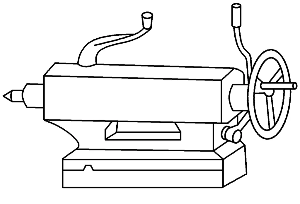
1) Manually move the tailstock along the bed ways to a suitable position, turn the tailstock clamping lever counterclockwise to fix the tailstock. Be careful not to use excessive force when moving the tailstock.
2) Move the quill clamping lever counterclockwise (to loosen), turn the handwheel to make the quill advance or retract. Turn the quill clamping lever clockwise to fix the quill in the selected position.
3) Clean the quill bore and the taper of the center, install the tailstock center; loosen the quill clamping lever, turn the handwheel to retract the quill and remove the tailstock center.