I. Structure of the Turning Tool
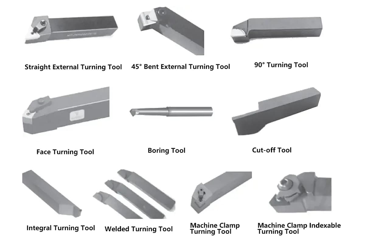
Turning tools are divided into four types based on structure: integral, welded, mechanical clamping, and indexable, with their structural characteristics and applicable occasions shown in Table 1.
Table 1 Structural Characteristics and Applicable Occasions of Turning Tools
| Name | Characteristics | Applicable Occasions |
| Integral Turning Tool | Made of integral high-speed steel, the edge can be sharpened very sharp | Small lathes or machining non-ferrous metals |
| Welded Turning Tool | Welded carbide blade, compact structure, flexible use | All kinds of turning tools, especially small tools |
| Mechanical Clamping Turning Tool | Avoids the defects such as stress and cracks caused by welding, high tool shank utilization, the blade can obtain the required parameters through sharpening; flexible and convenient use | External turning tools, end face turning tools, internal hole turning tools, cutoff turning tools, threading turning tools, etc. |
| Indexable Turning Tool | Avoids the disadvantages of welded turning tools, the blade can be quickly changed and indexed; high productivity; stable chip breaking; coated blades can be used | Large and medium-sized lathes for machining external circles, end faces, boring, suitable for automatic lines, CNC machine tools |
II. Composition and Angles of the Turning Tool
The turning tool is the simplest form of single-edge cutting tool, and all other complex tools can be considered as combinations and evolutions of the turning tool. The definitions of turning tool angles are applicable to other tools as well.
1. Composition of the Turning Tool
The turning tool consists of the tool head (cutting part) and the tool body (holding part). The cutting part of the turning tool is composed of three surfaces, two edges, and one tip. The composition of the turning tool is shown in Figure 1.
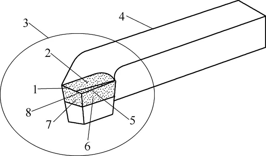
1—Secondary cutting edge
2—Front face
3—Tool head
4—Tool body
5—Main cutting edge
6—Main rear face
7—Secondary rear face
8—Tool tip
(1) Front face
The surface through which the chips flow out during cutting.
(2) Main rear face
The surface opposite to the workpiece surface being machined during cutting.
(3) Secondary rear face
The surface opposite to the already machined surface of the workpiece during cutting.
(4) Main cutting edge
The intersection of the front face and the main rear face. It can be straight or curved, bearing the main cutting work.
(5) Secondary cutting edge
The intersection of the front face and the secondary rear face. It generally undertakes a small amount of cutting work.
(6) Tool tip
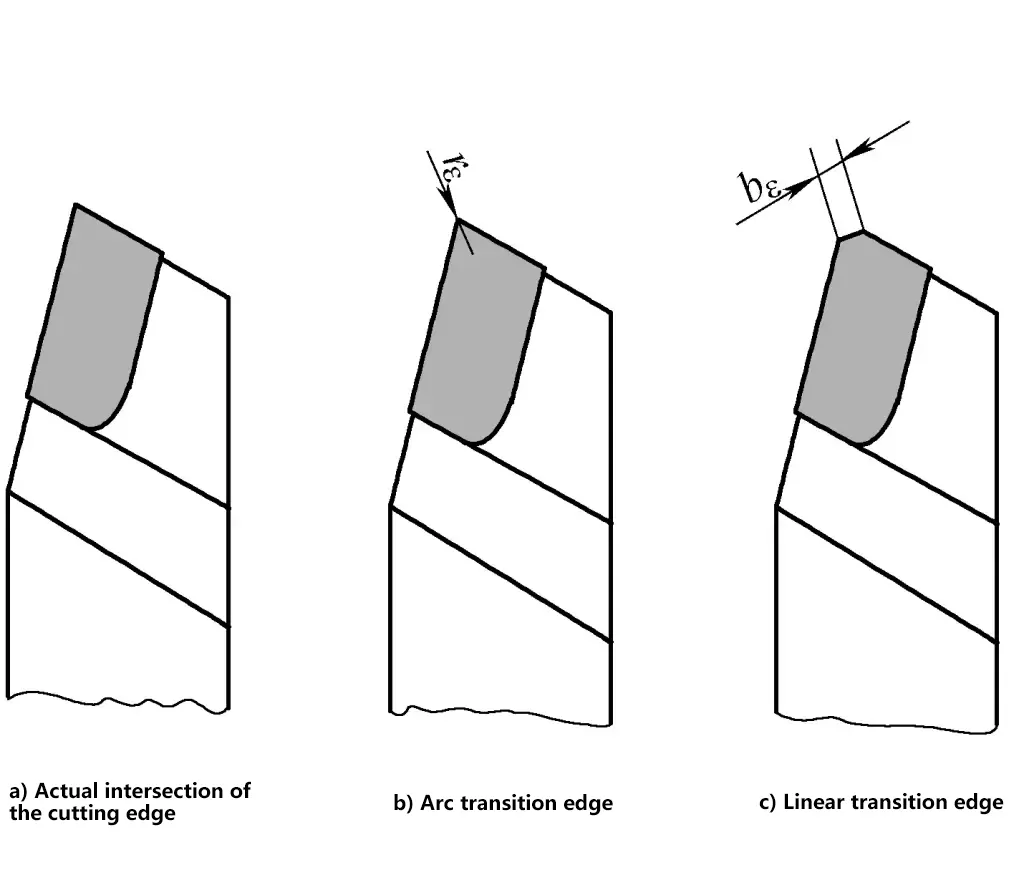
The intersection part of the main cutting edge and the secondary cutting edge. To strengthen the tool tip, it is often ground into a round arc or a short straight line to form a transitional edge, as shown in Figure 2.
2. Angles of the Turning Tool
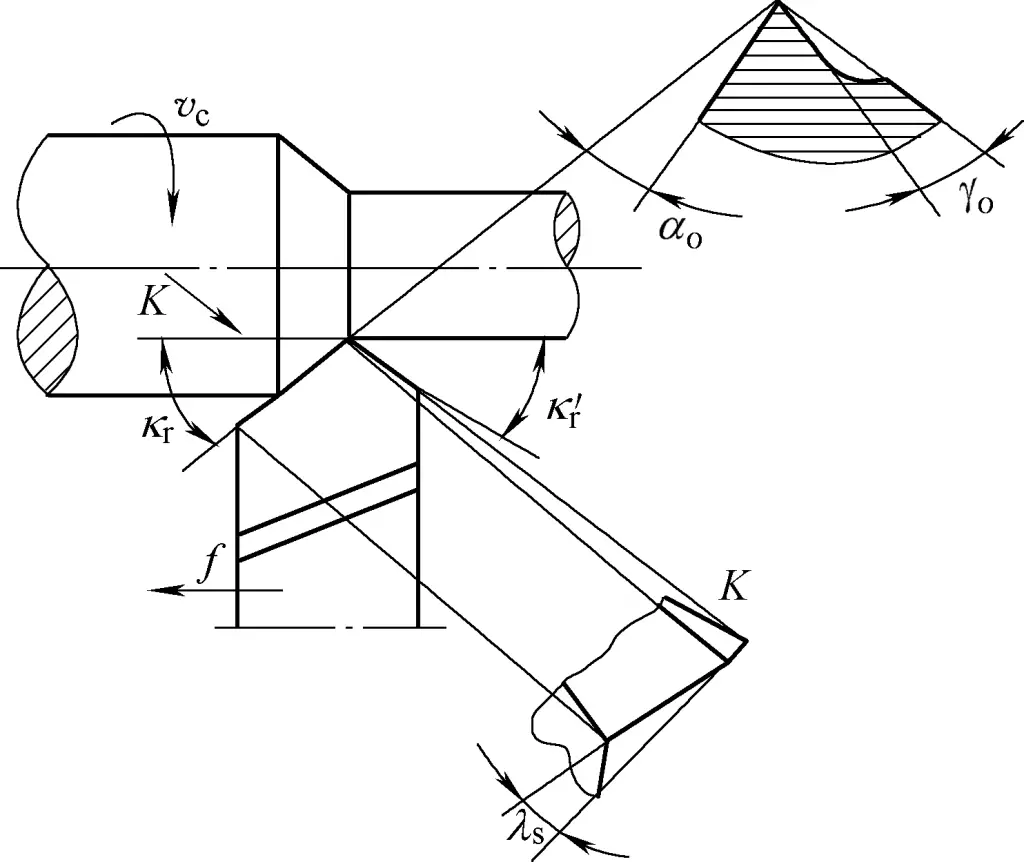
The main angles of the turning tool include the rake angle γ o , clearance angle α o , principal cutting edge angle k r , secondary cutting edge angle k‘ r , and inclination angle λ s , as shown in Figure 3. The angles of the turning tool play an important role in machining quality and productivity.
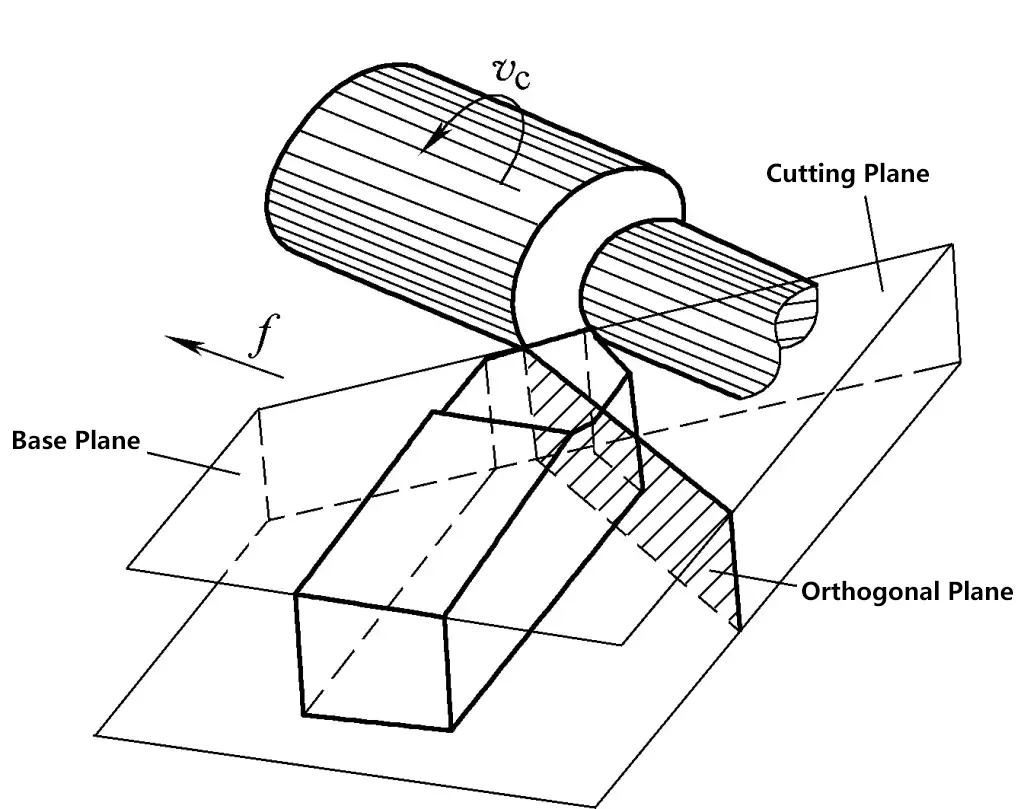
During cutting, the tool head forms three surfaces, two edges, and one tip, constituting the actual effective angles of the turning tool. The base of the turning tool is horizontal and parallel to the bottom of the turning tool. The cutting plane, orthogonal plane, and base are perpendicular to each other, as shown in Figure 4.
(1) Rake angle γo
It is the angle between the rake face and the base plane, indicating the inclination of the rake face. The rake angle can be positive, negative, or zero. If the rake face is below the base plane, the rake angle is positive; otherwise, it is negative; if coinciding, it is zero. Generally, the mentioned rake angle refers to the positive rake angle.
Figure 5 shows the sectional view of the rake angle and clearance angle. Increasing the rake angle can make the cutting edge sharper, reduce cutting force, lower cutting temperature, decrease tool wear, and improve surface finish quality. However, too large a rake angle will reduce the strength of the cutting edge, making it prone to damage.
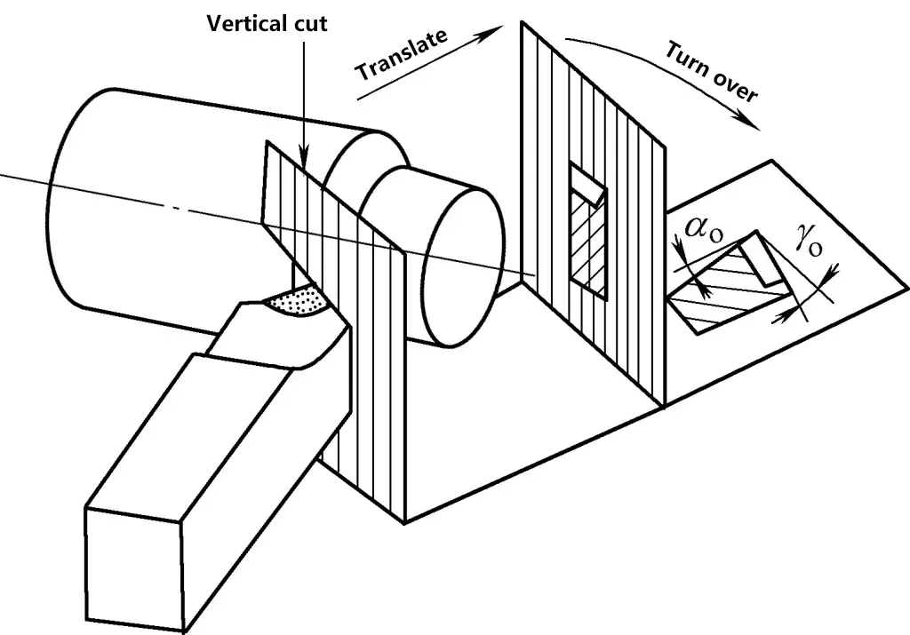
For machining steel parts (plastic materials, etc.) with carbide turning tools, the rake angle is generally chosen to be 10°~20°, and for machining gray cast iron (brittle materials, etc.), the rake angle is generally chosen to be 5°~15°. A larger rake angle can be selected for finishing, and a smaller one should be chosen for rough machining. When the strength and hardness of the workpiece material are high, a smaller rake angle is chosen, sometimes even a negative value.
(2) Clearance angle αo
It is the angle between the principal flank face and the cutting plane, indicating the inclination of the principal flank face. The function of the clearance angle is to reduce the friction between the principal flank face and the workpiece, and it affects the strength and sharpness of the cutting edge. Generally, the clearance angle α o can be chosen to be 5°~7°.
(3) Principal cutting edge angle kr
It is the angle between the main cutting edge and the feed direction projected on the base plane. The function of the principal cutting edge angle is to affect the working length of the cutting edge, back force, tip strength, and heat dissipation conditions. The smaller the principal cutting edge angle, the longer the working length of the cutting edge, the better the heat dissipation conditions, but the greater the back force.
Commonly used principal cutting edge angles for turning tools are 45°, 60°, 75°, 90°. A smaller value can be chosen when the workpiece has good rigidity. When turning slender shafts, to reduce the back force and prevent bending deformation of the workpiece, a larger value should be selected. The principal cutting edge angle of the turning tool is shown in Figure 6.
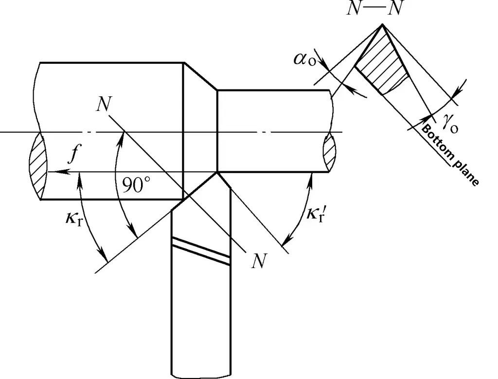
(4) Secondary cutting edge angle k‘r
It is the angle between the secondary cutting edge and the feed direction projected on the base plane. The function of the secondary cutting edge angle is to affect the surface roughness of the machined surface, reducing the secondary cutting edge angle can decrease the roughness value of the machined surface. The secondary cutting edge angle of the turning tool is shown in Figure 6. k‘ r is generally chosen to be 5°~15°, 5°~10° for fine turning, and 10°~15° for rough turning.
(5) Lead angle λs
It is the angle between the main cutting edge and the base plane, with the tool tip being the highest point of the cutting edge as a positive value, otherwise as a negative value. The function of the lead angle mainly affects the strength of the main cutting edge and controls the direction of chip flow.
Using the bottom surface of the tool shank as a reference, when the tool tip is the highest point of the main cutting edge, λ s >0°, chips flow towards the surface to be machined, as shown in Figure 7a; when the main cutting edge is parallel to the bottom surface of the tool shank, λ s =0°, chips flow in a direction perpendicular to the main cutting edge, as shown in Figure 7b; when the tool tip is the lowest point of the main cutting edge, λ s <0°, chips flow towards the machined surface, as shown in Figure 7c.
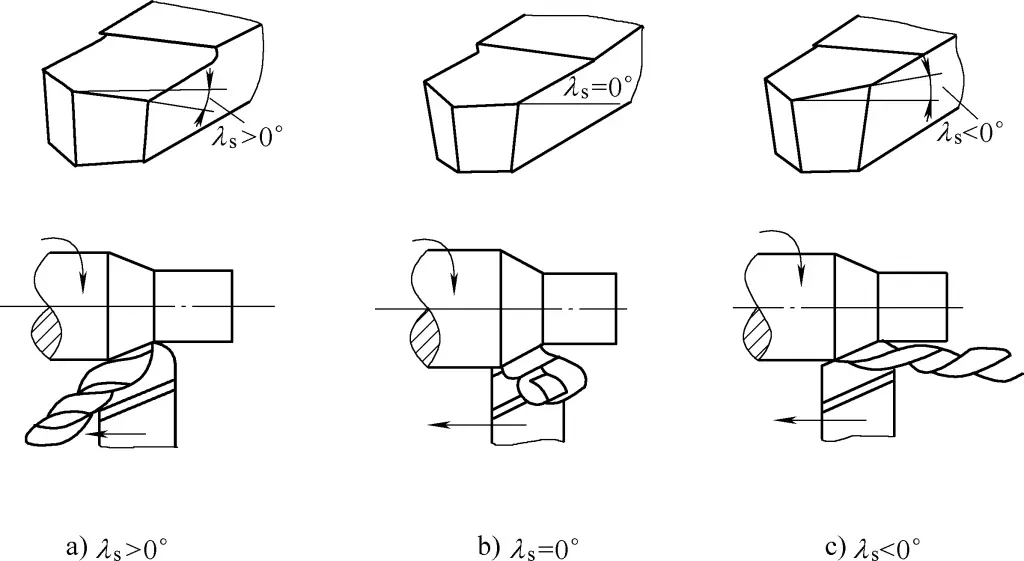
Generally, λs is chosen between -5°~+5°. For rough machining, λs is often negative, although chips flow towards the machined surface, it ensures the strength of the main cutting edge. For fine machining, λs is often positive, making chips flow towards the surface to be machined, thus not scratching the machined surface.
III. Sharpening of the turning tool
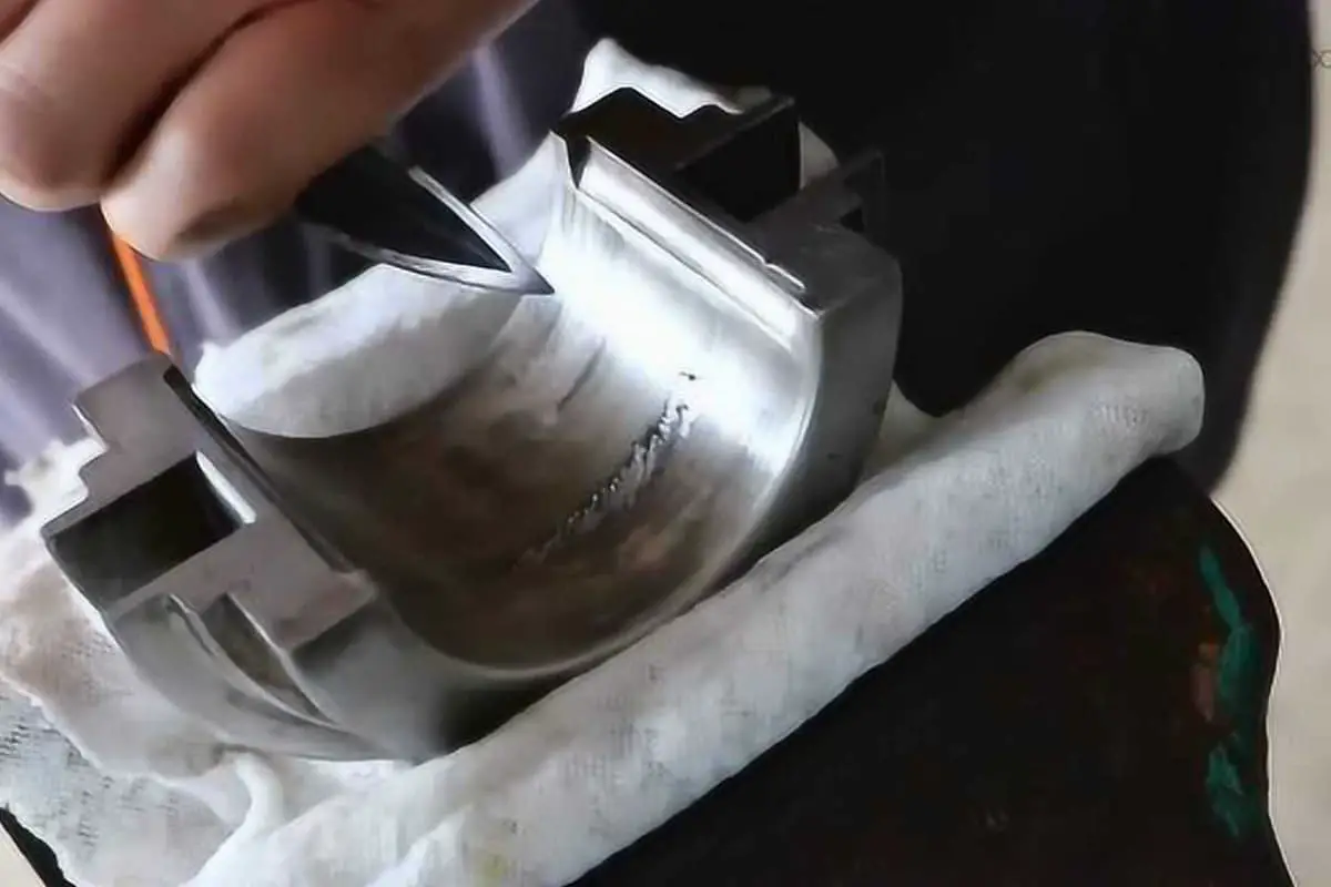
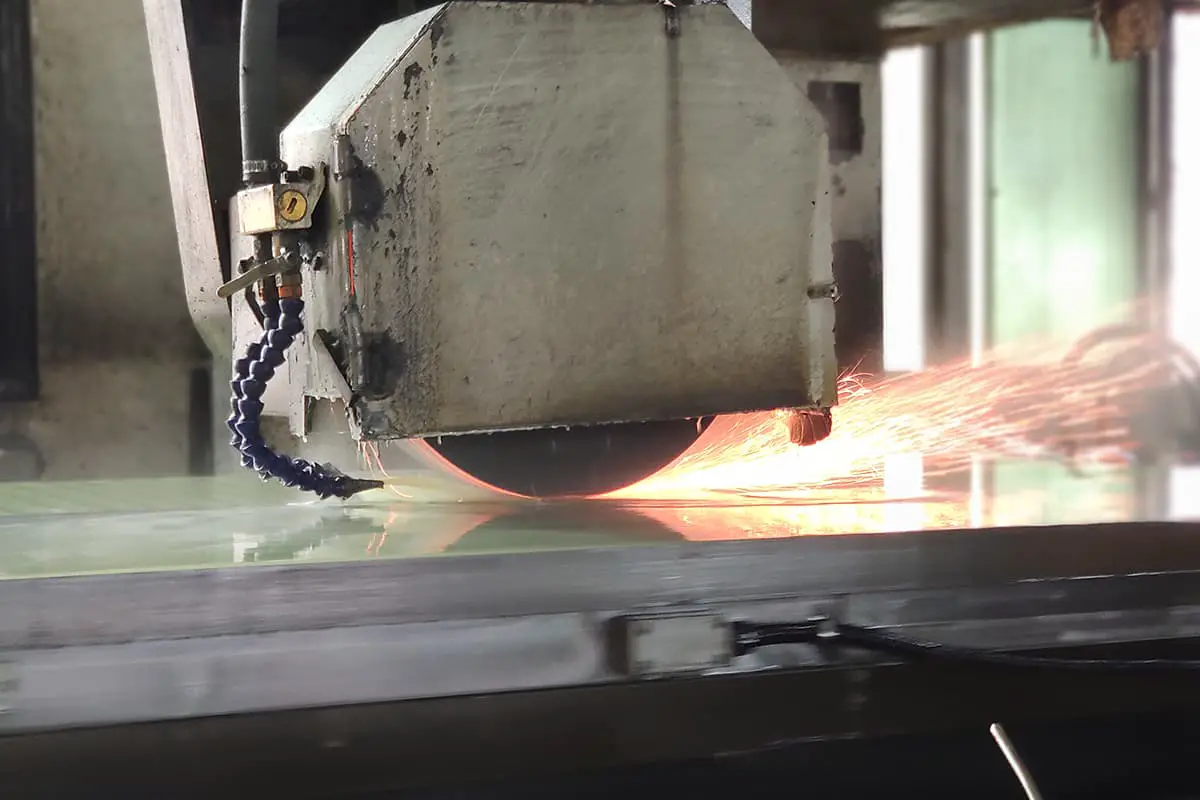
Re-sharpening of the turning tool after it becomes blunt is done on a grinding wheel. Grind high-speed steel turning tools with an aluminum oxide grinding wheel (white), and grind carbide tool tips with a silicon carbide grinding wheel (green).
1. Steps in sharpening the turning tool
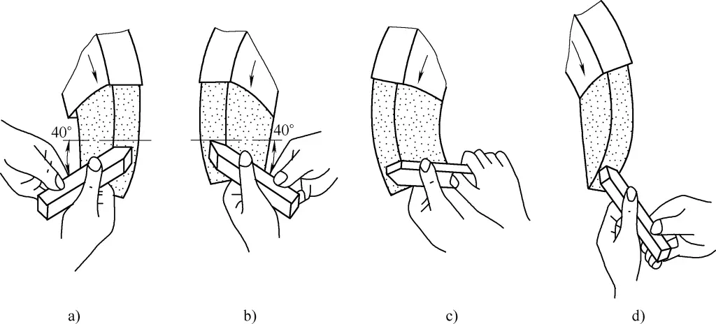
- Grind the principal flank face, while also grinding out the principal cutting edge angle and principal clearance angle, as shown in Figure 8a.
- Grind the secondary flank face, while also grinding out the secondary cutting edge angle and secondary clearance angle, as shown in Figure 8b.
- Grind the rake face, while also grinding out the rake angle, as shown in Figure 8c.
- Sharpen each face and the tip, as shown in Figure 8d.
2. Posture and method for sharpening the turning tool
- Stand at the side of the grinding wheel to prevent injury from flying fragments in case the wheel shatters.
- When holding the tool with both hands, maintain a certain distance, and clamp your elbows to your waist to reduce vibration during sharpening.
- When sharpening a tool, the cutting tool should be placed at the horizontal center of the grinding wheel, with the tip slightly tilted upwards by 3° to 8°. After the cutting tool contacts the grinding wheel, it should move horizontally in the left and right direction. When the cutting tool leaves the grinding wheel, it needs to be lifted upwards to prevent the sharpened cutting edge from being damaged by the grinding wheel.
- When sharpening the back surface of the tool, the tail of the tool bar should be tilted to the left by an angle equal to the primary clearance angle; when sharpening the secondary back surface, the tail of the tool bar should be tilted to the right by an angle equal to the secondary clearance angle.
- When grinding the tip’s radius, it is common to hold the front end of the cutting tool with the left hand as a pivot and rotate the tail of the cutting tool with the right hand.
IV. Safety Knowledge for Grinding Cutting Tools
- Before grinding tools, it is necessary to first check for any cracks in the grinding wheel, ensure the grinding wheel shaft nut is tightened, and use it after a trial run to prevent the grinding wheel from breaking or flying out and causing injury.
- Do not apply too much force when grinding tools, as it may cause your hand to slip and come into contact with the surface of the grinding wheel, resulting in industrial accidents.
- Wear protective goggles when sharpening tools to prevent sand and chips from flying into the eyes.
- Do not stand directly in front of the rotating direction of the grinding wheel when sharpening tools, to prevent accidents.
- When sharpening small tool heads, they must be mounted on the tool bar.
- The gap between the grinding wheel holder and the grinding wheel should not be more than 3mm; if it is found to be too large, it should be adjusted accordingly.
V. Installation of Cutting Tools
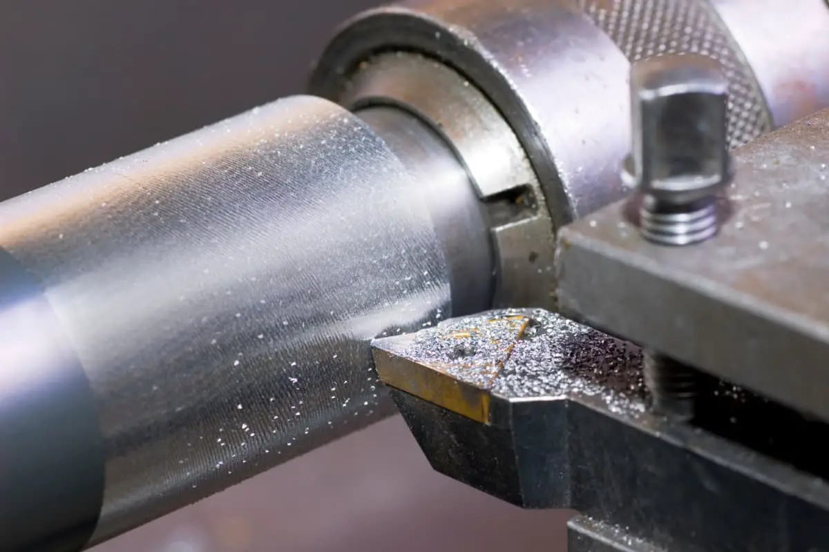
The cutting tool must be correctly and securely installed on the tool holder, as shown in Figure 9. When installing the cutting tool, the tip must be precisely aligned with the center of rotation of the workpiece, otherwise, it will be difficult to remove the center protrusion of the workpiece; and feed from the center outward as much as possible, lock the saddle if necessary. The following points should be noted when installing the cutting tool:
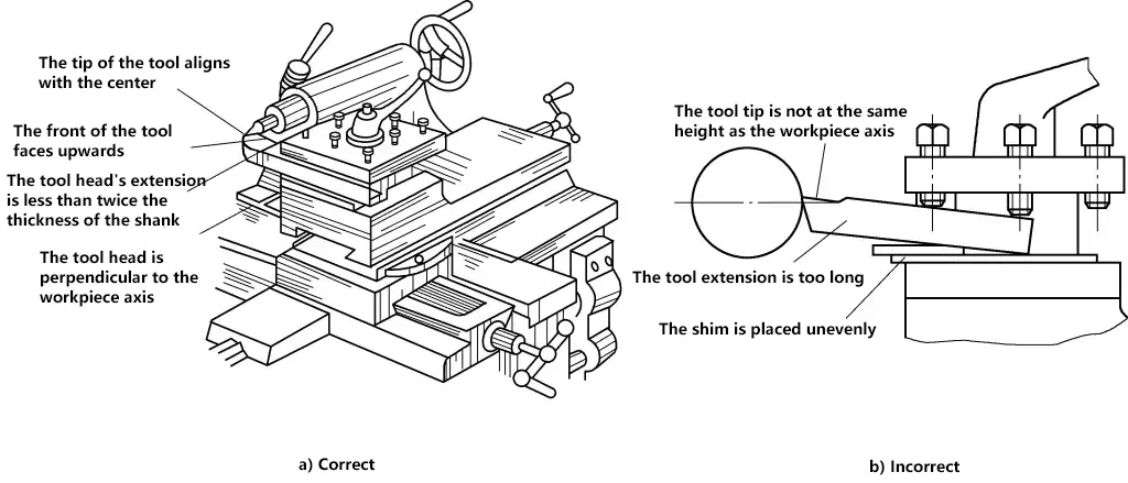
1. The tool head should not protrude too long
The tool head should not protrude too long, otherwise, it will easily vibrate during cutting, affecting the machining accuracy and surface roughness of the workpiece. Generally, the protrusion length of the tool head should not exceed 1.5 to 2 times the thickness of the tool bar, and it is sufficient to see the tool tip cutting.
2. The tool tip should be at the same height as the centerline of the lathe spindle
If the cutting tool is installed too high, the back angle will decrease, causing intense friction between the main back surface of the cutting tool and the workpiece; if installed too low, the front angle will decrease, making cutting difficult and causing the tool tip to chip. The height of the tool tip can be adjusted according to the height of the tailstock center. The installation of the cutting tool is shown in Figure 9a.
3. The shim under the cutting tool should be flat
The shim under the cutting tool should be flat and use thick shims as much as possible to reduce the number of shims. After adjusting the height of the tool tip, at least two screws should be used to tighten the cutting tool alternately.

