I. Basic Process Knowledge
1. Purpose of Marking
Marking is an operation of drawing processing boundary lines on blanks or semi-finished products according to drawing requirements. The purposes of marking before processing parts are as follows:
- Determine the processing position and allowance of each processing surface on the workpiece, providing clear processing indicators to guide the processing.
- Identify and eliminate blanks that do not meet drawing requirements.
- Arrange materials rationally on sheet metal to save materials and reduce costs.
2. Types of Marking
Marking is divided into plane marking and three-dimensional marking. The operation of clearly indicating the processing boundary lines of a workpiece by marking only on one plane of the workpiece is called plane marking, as shown in Figure 1a. The operation of clearly indicating the processing boundary lines of a workpiece by marking on several surfaces in different directions of the workpiece is called three-dimensional marking, as shown in Figure 1b.
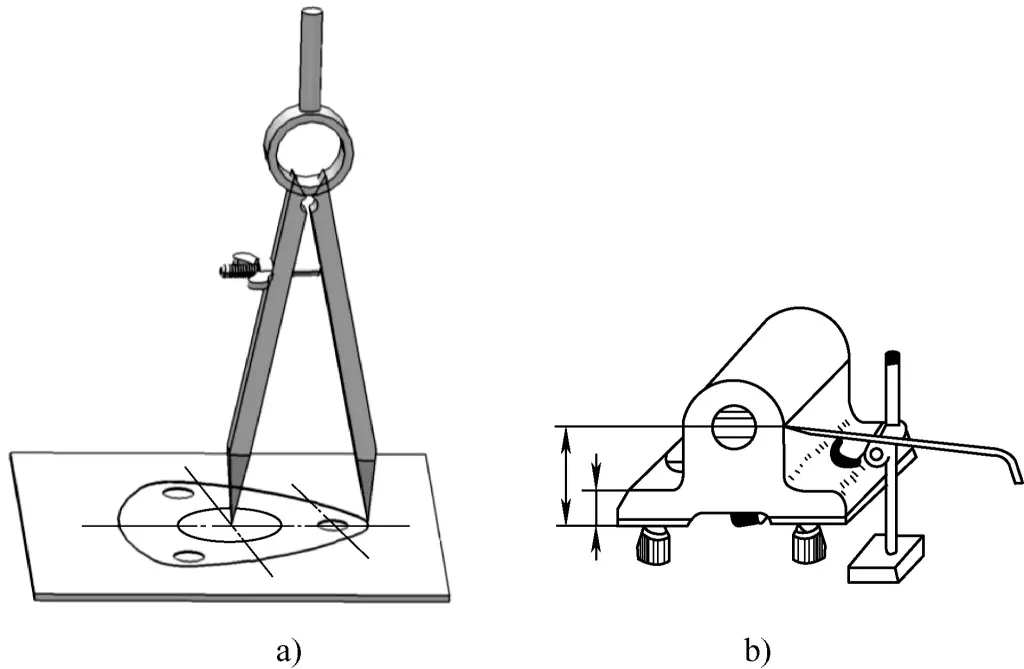
a) Plane Marking
b) Three-dimensional Marking
3. Requirements for Marking
- Adopt reasonable positioning and alignment methods, correctly use marking tools to ensure the accuracy of marked dimensions. However, it should be noted that: due to the certain width of the marked lines and inevitable errors when using marking tools and measuring and adjusting dimensions, the marked lines cannot be absolutely accurate. Generally, marking accuracy can reach 0.25~0.5mm.
- Correctly use marking tools to make the marked lines clear and uniform.
- Three-dimensional marking should ensure that the marked lines are perpendicular to each other in length, width, and height directions.
4. Marking Reference and Its Selection
The marking reference refers to carefully analyzing the part drawing and selecting one or several geometric elements (lines or surfaces) on the blank part as the basis for marking (starting position for marking), in order to more accurately and quickly mark the processing position lines of other geometric elements (lines or surfaces) on the part to be processed. Such lines or surfaces are called marking references.
Marking should always start from the marking reference, and reasonably selecting the marking reference is the key to improving marking quality and efficiency. When selecting the marking reference, try to keep it consistent with the design reference of the part, such as selecting the centerline or center plane of the main hole as the marking reference.
(1) Types of marking reference selection for plane marking
- Use two perpendicular edges as marking references, as shown in Figure 2a.
- Use one edge and one centerline as marking references, as shown in Figure 2b.
- Use two perpendicular centerlines as marking references, as shown in Figure 2c.

a) Using perpendicular edges as references
b) Using bottom edge and centerline as references
c) Using perpendicular centerlines as references
(2) Types of marking reference selection for three-dimensional marking of parts
- Use two perpendicular planes (already processed) as marking references, as shown in Figure 3a.
- Use one processed surface and one imaginary center plane as marking references, as shown in Figure 3b.
- Use two perpendicular imaginary center planes as marking references, as shown in Figure 3c.

a) Using two perpendicular planes as references
b) Using bottom surface and center plane as references
c) Using perpendicular center planes as references
(3) Specific application of marking references
Figure 4 shows the specific method of using marking references for three-dimensional marking. This figure represents the situation where marking references are used for part alignment and blank marking in the length and height directions (here is the orthographic projection direction) of a fork part.
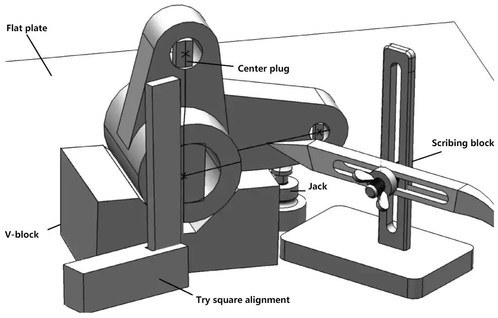
After marking the lines on this projection surface, it can be rotated 90° and placed to mark the processing lines on other projection surfaces (width and height, length and width). Specific alignment and marking methods are described in “Basic Operational Skills”.
II. Basic Operational Skills
1. Usage Methods and Precautions for Common Marking Tools
The usage methods and precautions for common marking tools are shown in Table 1.
Table 1 Usage Methods and Precautions for Common Marking Tools
| Tool Name | Illustration | Usage Method and Precautions | |
| Scriber | 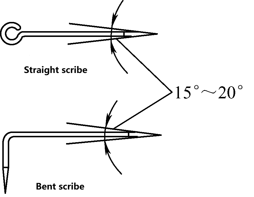 | Straight-head and bent-head scribers both have cone angles of 15°~20° | |
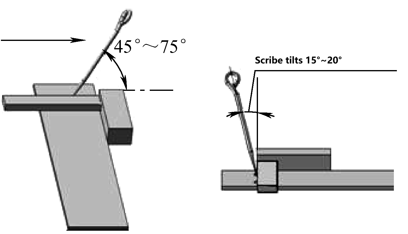 | When scribing along the edge of a guiding tool (such as a square, steel ruler, or template), the scriber should be tilted at a certain angle in both front-back and left-right directions, with the tip pressed against the edge of the guiding tool | ||
| Steel Ruler | 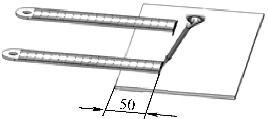 | Use a steel ruler in combination with a scriber to measure dimensions (such as the 50mm edge distance shown in the figure) | |
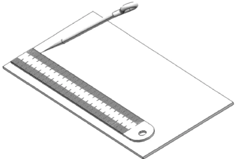 | Use a steel ruler in combination with a scriber to draw lines parallel to the side of the workpiece | ||
| Square | 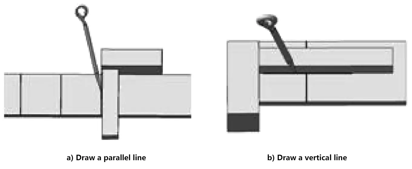 | Place the square’s base against a reference edge of the workpiece, and use a scriber to draw parallel lines (see figure a) or perpendicular lines (see figure b) | |
| Divider | Common Divider | 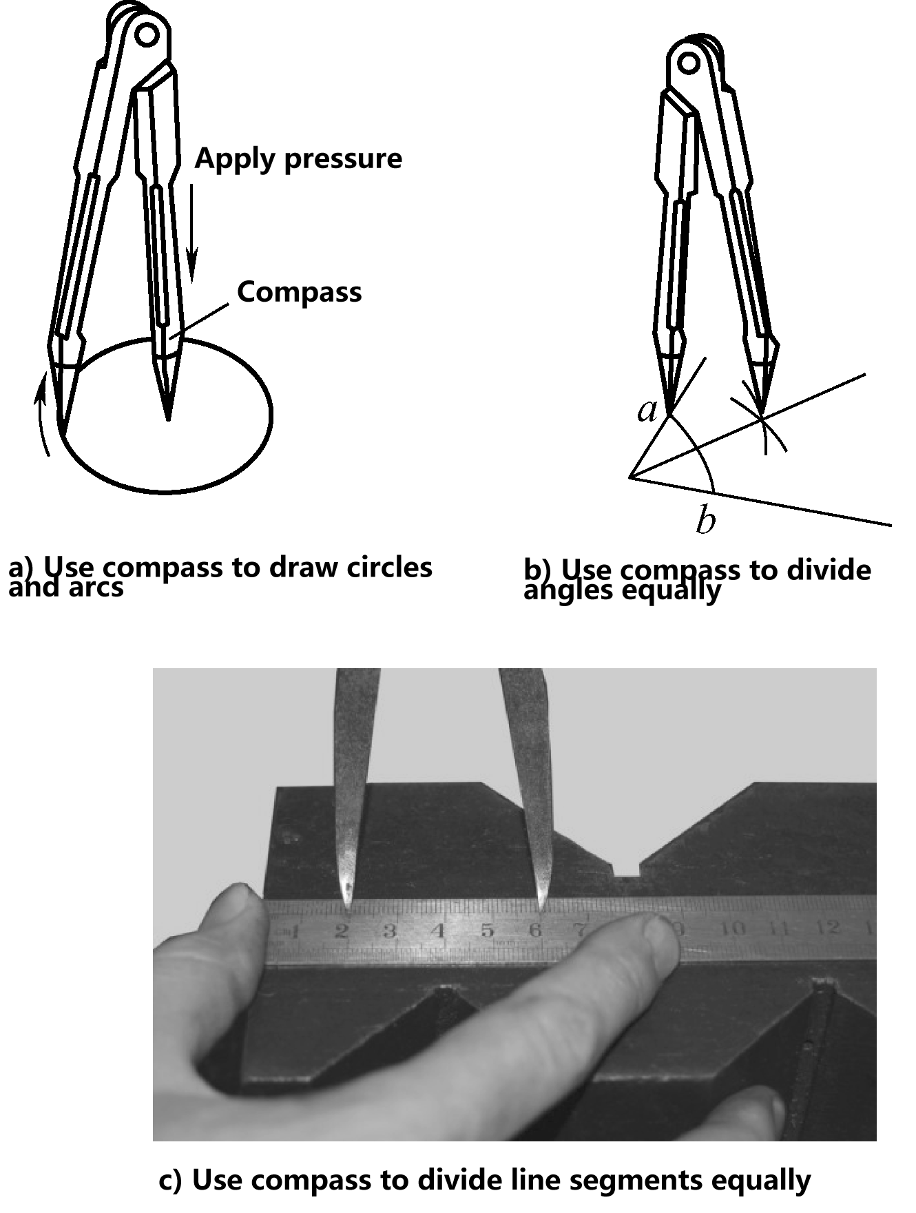 | 1) As shown in figure a, when scribing circles and arcs, pressure should be applied to the divider point serving as the center of rotation; when scribing small circles and arcs, the divider points should be able to close tightly; 2) As shown in figure b, use a divider to divide angles; 3) As shown in figure c, measure dimensions on a steel ruler and then use a divider to divide line segments. Note that when measuring dimensions, it should be repeated several times to avoid measurement errors |
| Long Divider | 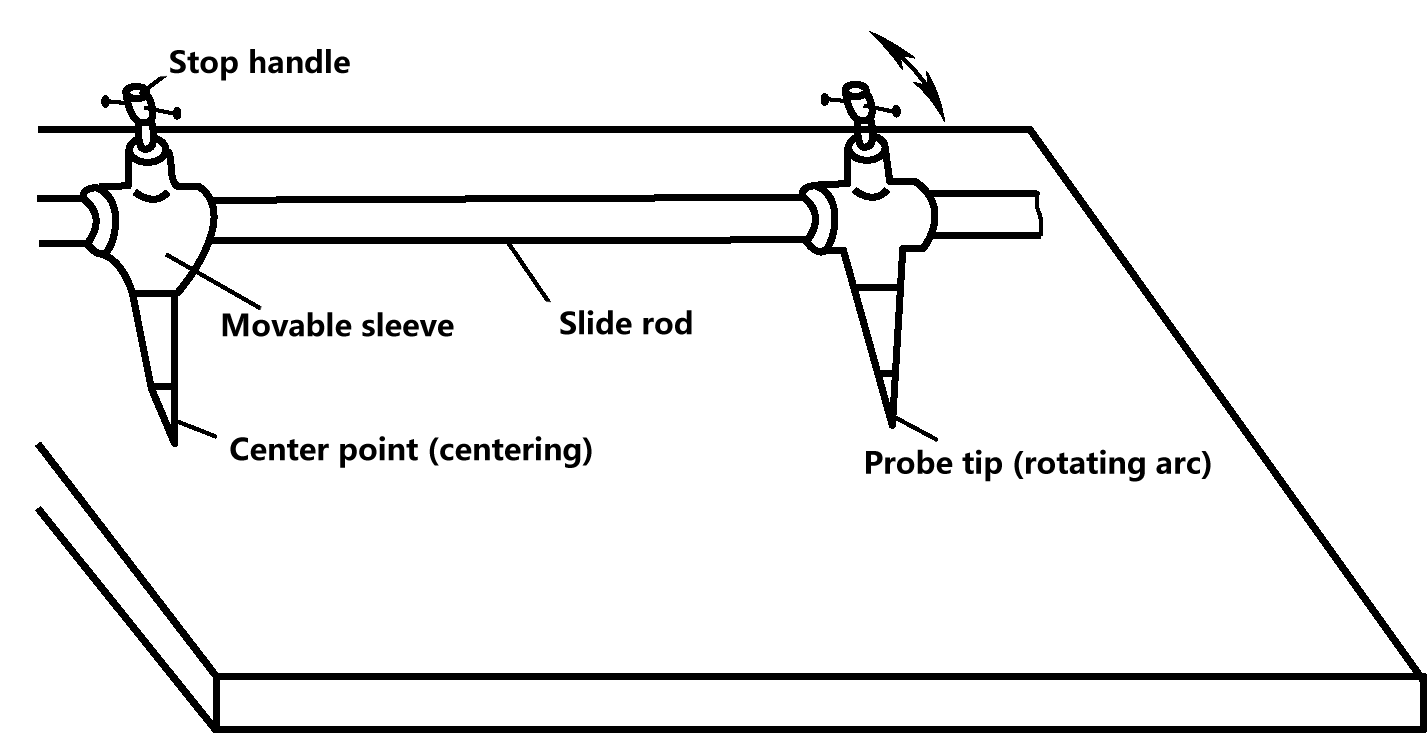 | Long dividers are mainly used for scribing large circles and arcs, measuring large dimensions, dividing angles and line segments, etc. A certain dimension can be obtained by moving the two compass legs on the sliding rod | |
| Height Gauge | 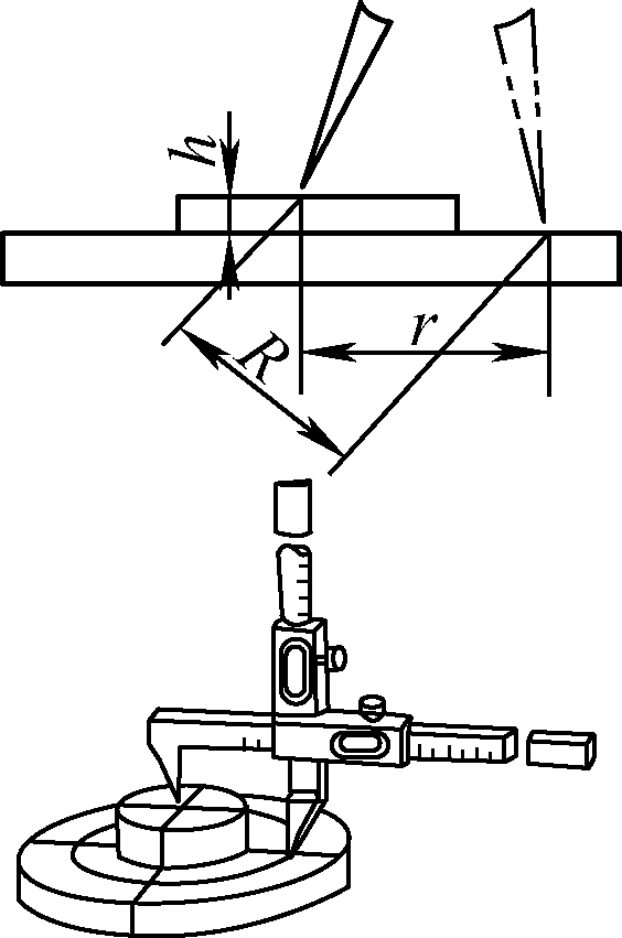 | If the height gauge requires scribing with the two points not in the same plane, for example, when the center is higher than the R=√(r2+h2) circular plane, the distance between the two points is not the radius of the circle to be scribed. In this case, the distance between the two points should be adjusted to R, as shown in the figure (R is the radius of the inclined circle, r is the radius of the horizontal circle, h is the vertical distance of the height difference between the two points) | |
| Scriber Block | 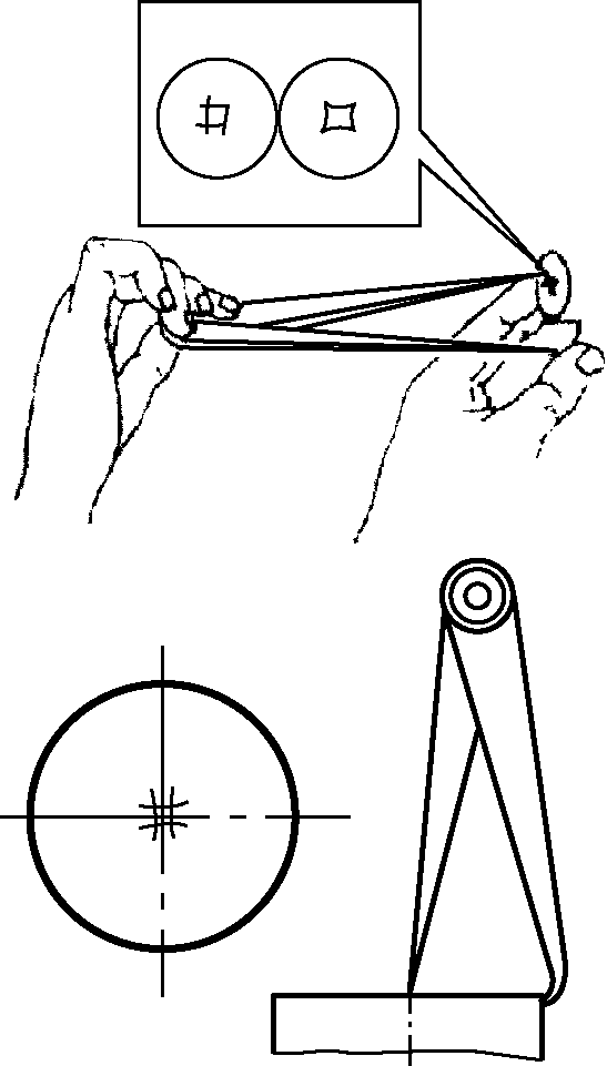 | The main use of a scriber block is to find the center of circular workpieces, and it can also be used to draw parallel lines. When scribing the center, care should be taken to keep the distance between the curved leg tip and the end face of the workpiece the same each time, otherwise the found center will be inaccurate | |
| Center Punch | 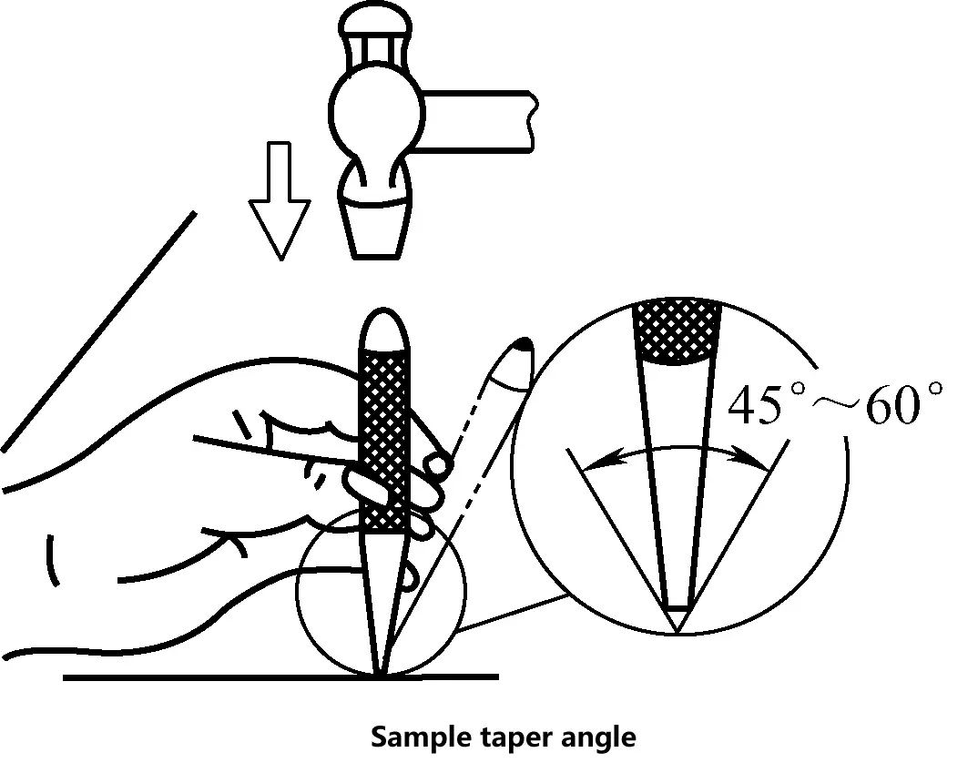 | The cone angle of a center punch is generally selected within the range of 45°~60°. For drilling center punches, the cone angle should be larger, while for marking after scribing, the cone angle should be appropriately smaller | |
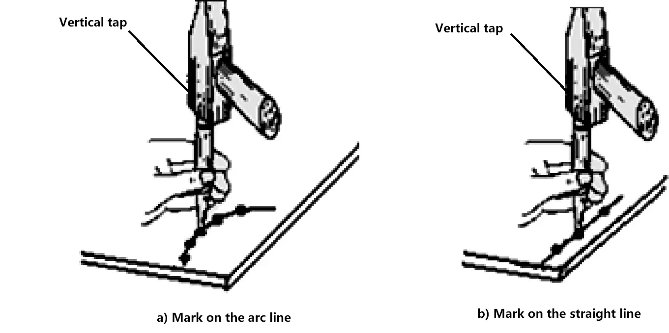 | Make small and uniform center punch marks at the intersection points of the scribed lines on the workpiece, so that the original lines and intersection points can still be found even after the scribed lines become blurred. Precautions for making center punch marks on scribed lines for marking are as follows: 1) As shown in figure a, the center punch marks on arc lines should be denser, i.e., the intervals between center punch marks should be smaller 2) As shown in figure b, the center punch marks on straight lines can be sparser, i.e., the intervals between center punch marks can be larger 3) It is forbidden to make center punch marks on processed part surfaces | ||
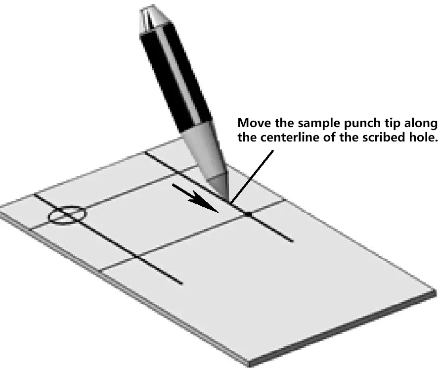 | Before drilling, a “center” punch mark should be made in the central area to allow the drill point at the cross-section of the drill bit to fall into the concave pit of the center punch mark. Therefore, the position of the center punch mark before drilling should be as accurate as possible to ensure the accuracy of the hole position during drilling | ||
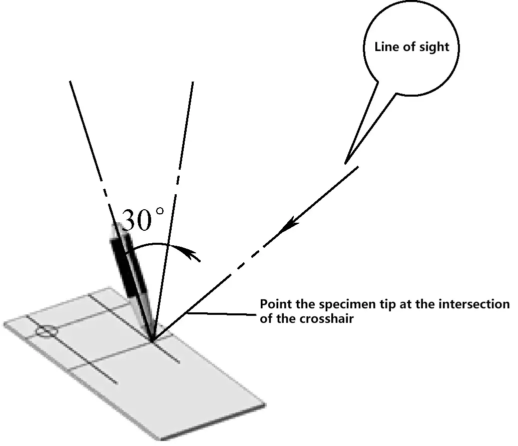 | The center punch should be at a 30° angle to the perpendicular line of the punch mark line | ||
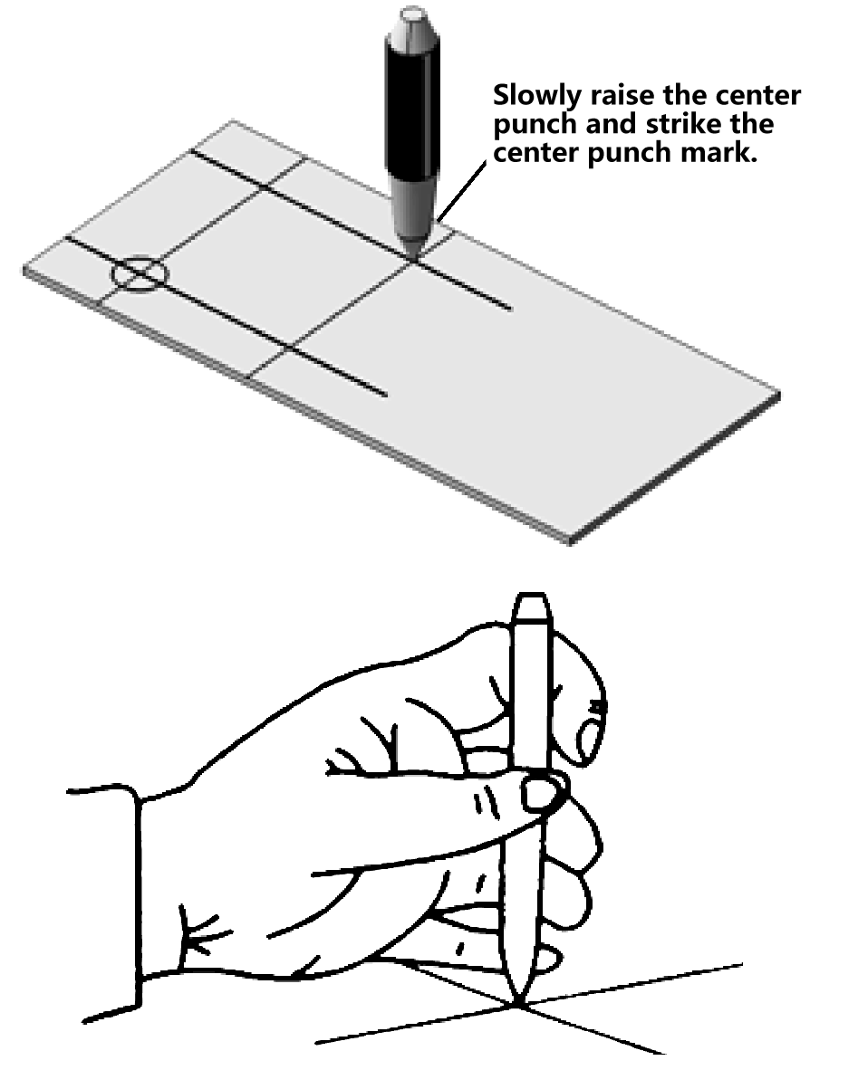 | 1) After aligning with the punch mark line, make the center punch perpendicular to the line; 2) After hammering once, rotate the sample punch by an angle and hammer again. Generally, rotate three times and hammer three times. | ||
| Height gauge | 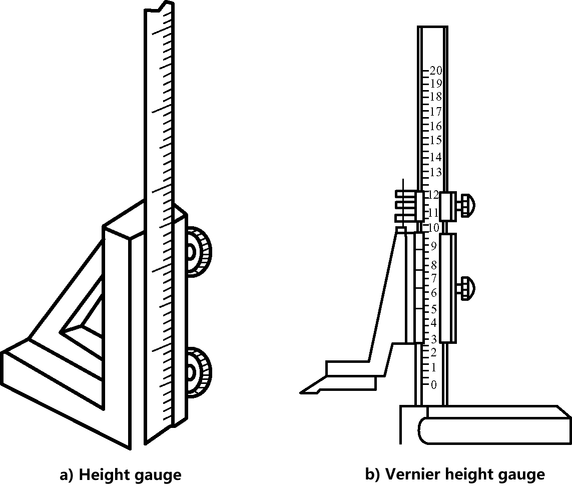 | 1) Figure a shows the external shape of a height gauge. The height gauge is often used with a marking gauge. A steel ruler is vertically fixed on the base, and a marking gauge is used to measure height dimensions. 2) Figure b shows the external shape of a vernier height gauge. It is a precision measuring tool suitable for marking semi-finished products (blanks), but not allowed to be used for marking rough castings. | |
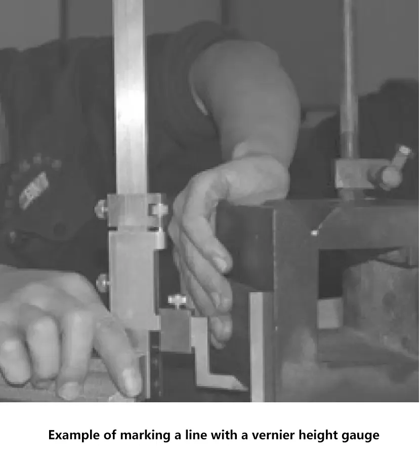 | 1) Before use, wipe clean the contact surfaces of the surface plate and the vernier height gauge to ensure smooth movement of the vernier height gauge without sticking. 2) In the horizontal direction, the vernier height gauge should be tilted about 15° when marking to reduce the impact between the blade tip and the surface being marked, prevent damage to the carbide marking tip, and reduce wear on the blade area. 3) When marking, adjust the marking height and lock the gauge frame with the fixing screw. 4) When marking, apply a certain pushing force to the vernier height gauge with your hand and move the body evenly to ensure clear lines. However, pay attention to the movement stroke to prevent the marking blade tip from hitting other devices (such as angle plates, square boxes, etc.). | ||
| Marking gauge | 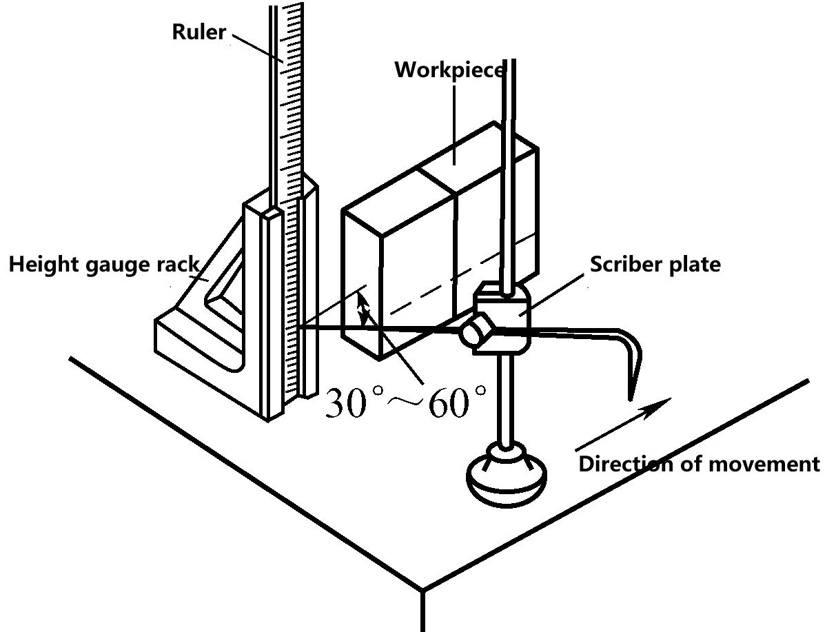 | The marking gauge is mainly used for surface marking on rough castings. When using the marking gauge with a height gauge to measure height dimensions and mark lines, adjust the straight leg tip of the marking gauge to a certain position and lock the butterfly nut. However, be careful not to tilt the angle too much to prevent vibration or loosening of the marking leg during marking. | |
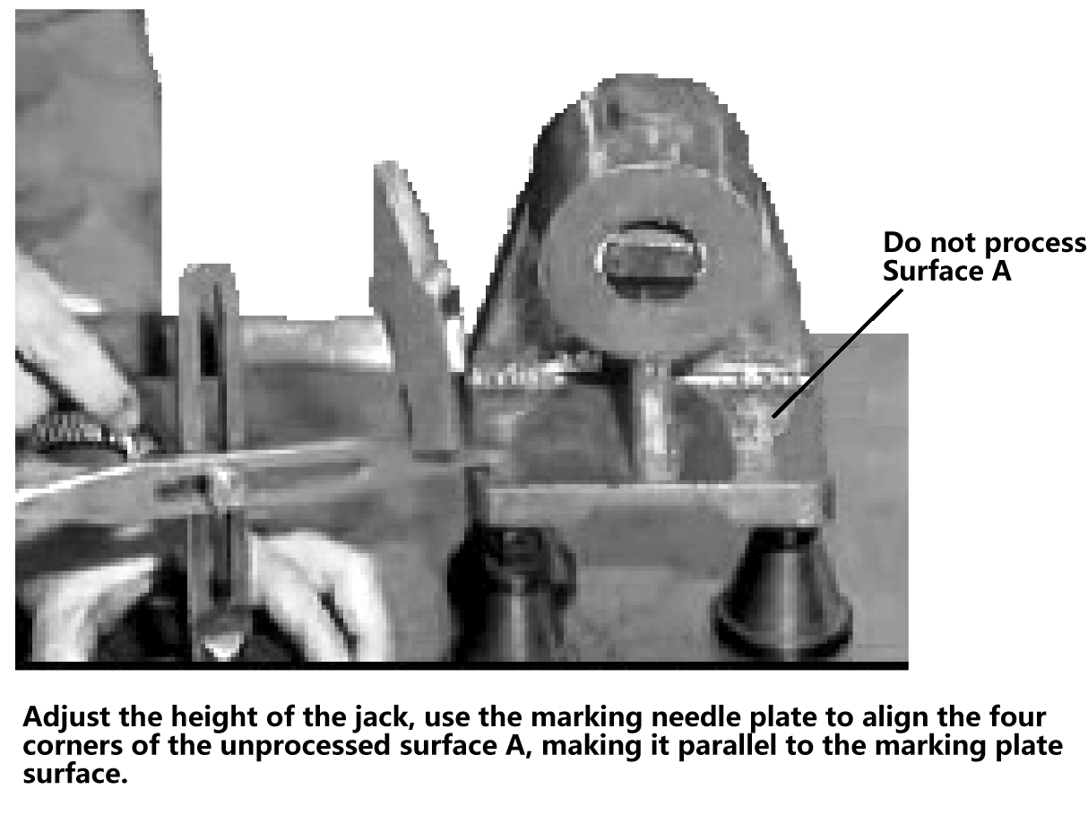 | The bent angle of the marking gauge is mainly used for alignment before three-dimensional marking on rough castings. | ||
| Marking accessories | V-block | 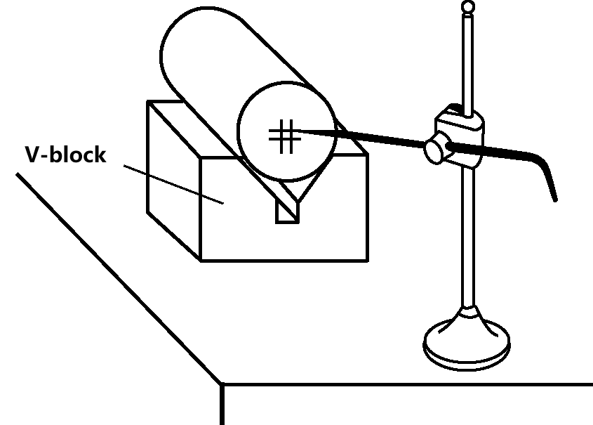 | V-blocks are used to support cylindrical workpieces, making the axis parallel to the upper surface of the marking plate, facilitating center finding and centerline marking with a marking gauge, as shown in the figure. V-blocks are made of cast iron, with adjacent sides perpendicular to each other. |
| Square box | 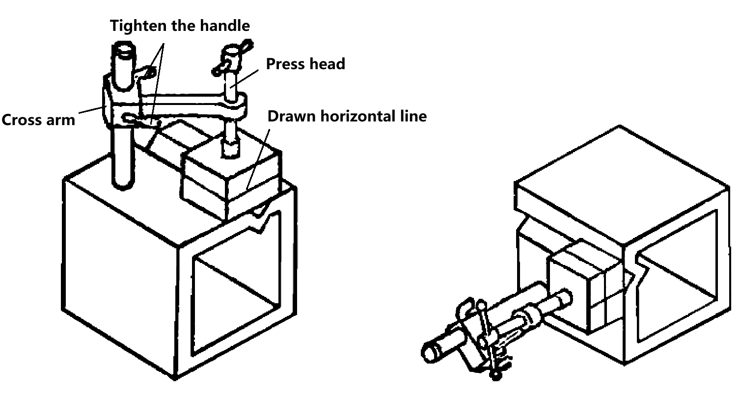 | The six faces of a square box are perpendicular to each other. It is used to hold smaller workpieces, and by flipping the square box, perpendicular straight lines can be marked on various surfaces of the workpiece. | |
| Surface plate | 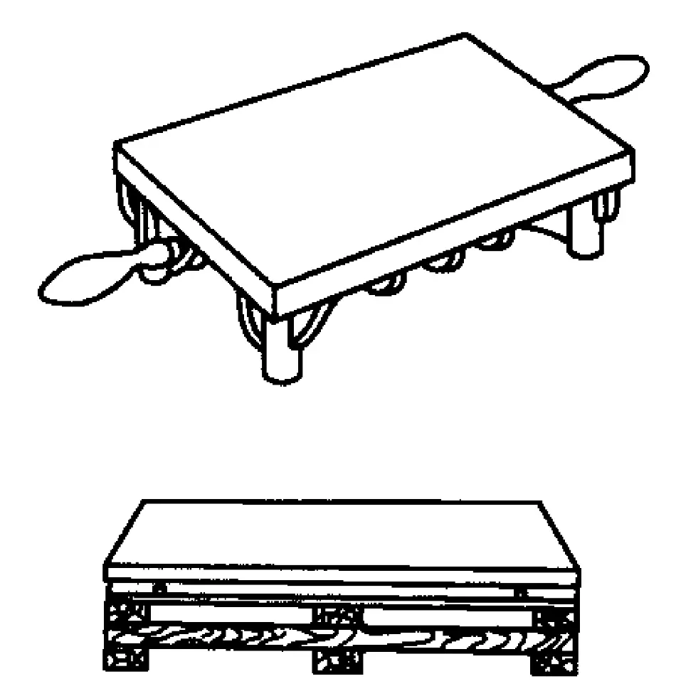 | The surface plate is made of cast iron and is a reference tool for marking. The upper surface of the surface plate serves as both the reference plane for marking and the base surface for placing workpieces and moving marking gauges. Therefore, the upper surface is required to be very flat and smooth, generally undergoing precision planing, scraping, and other fine machining processes. | |
| Jack | 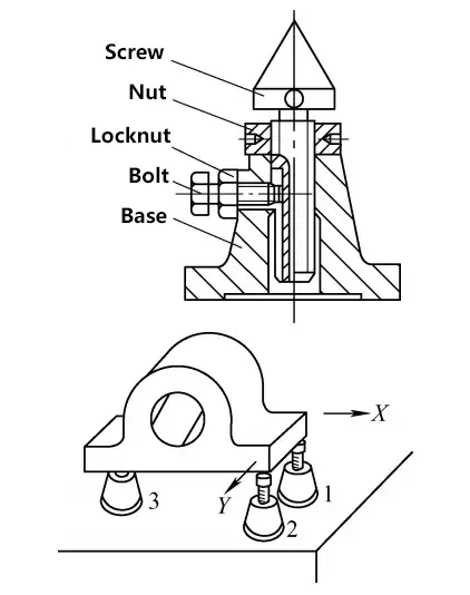 | Jacks are used to support rough castings or irregular workpieces on the surface plate for three-dimensional marking. Due to their adjustable height, they are convenient for aligning the horizontal position of workpieces. When in use, typically three jacks are used to support a workpiece. | |
2. Alignment and material borrowing during marking
(1) Alignment
1) Concept of alignment
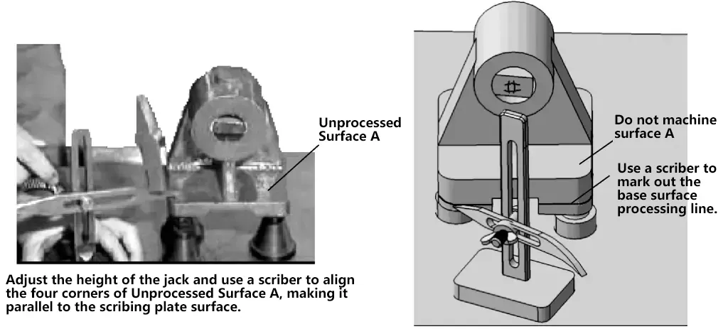
Alignment is the process of checking or aligning relevant unprocessed surfaces of the workpiece using marking tools before marking operation, based on processing requirements. This ensures that the marked lines are centered, parallel, or perpendicular to the relevant surfaces, and achieves uniform dimensions and reasonable machining allowances between processed and unprocessed surfaces. Figure 5 shows an alignment step before three-dimensional marking of a bearing housing casting.
2) Alignment methods
Figure 6 shows an example of marking a bearing housing casting. Due to the uneven thickness of the base, alignment should be performed using the unprocessed surface A as a reference when marking. After surface A is leveled horizontally, mark the processing line for the bottom surface to ensure relatively uniform thickness of the base. When the inner hole and outer circle of the upper part are not concentric, use the outer circle as the alignment reference, find the center, and then mark the processing line for the inner hole. The following points should be mastered during alignment:
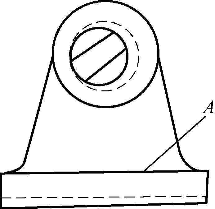
- To ensure equal distances between unprocessed and processed surfaces at all points, the unprocessed surface should be leveled horizontally or vertically (when the unprocessed surface is in a horizontal or vertical position).
- When there are multiple unprocessed surfaces, start aligning from the largest surface area while considering other unprocessed surfaces to ensure uniform wall thickness and concentricity of holes with hubs or bosses as much as possible.
- When there are no unprocessed surfaces, use the rough hole outline and boss positions of the processed surface for alignment.
- For multi-hole housings, ensure that all holes have machining allowances and are as concentric as possible with the bosses.
(2) Material borrowing
Material borrowing is a remedial marking method that involves redistributing machining allowances on various processed surfaces through trial marking to meet processing requirements.
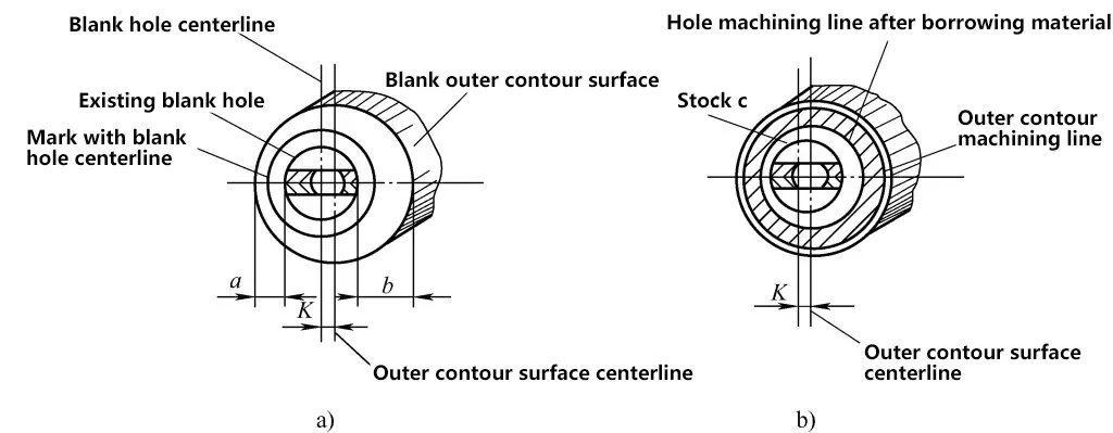
Figure 7a shows a sleeve casting. The inner surface of the sleeve is to be processed, but since the center of the rough hole does not align with the center of the outer profile, it is obviously inappropriate to use the existing rough hole center as a reference for marking. This would result in uneven sleeve wall thickness, making it impossible to guarantee the machining dimensions of the sleeve’s outer diameter. Now, try using the material borrowing method for marking.
a) Mark the processing hole circle using the rough hole center as a reference
b) Mark the processing hole circle using the outer profile surface center as a reference
As shown in Figure 7a, before marking, first measure and analyze various parts of the casting. From the measurements, it is known that the offset between the rough hole center and the profile center is K. If marking is done using the existing rough hole center, it will inevitably cause uneven thickness of the sleeve hole wall, leading to part rejection. After measurement and analysis, it is found that the minimum wall thickness a is greater than the required thickness in the drawing, indicating that the casting can meet processing requirements through material borrowing.
After the above analysis, now use the outer profile surface of the casting as the marking reference for alignment and marking. The marking result is shown in Figure 7b. As can be seen from Figure 7b, there is sufficient machining allowance at the minimum wall thickness c, and after machining according to this marking, there is also sufficient machining allowance for the outer circle of the sleeve.
3. Common marking methods
(1) Basic marking methods
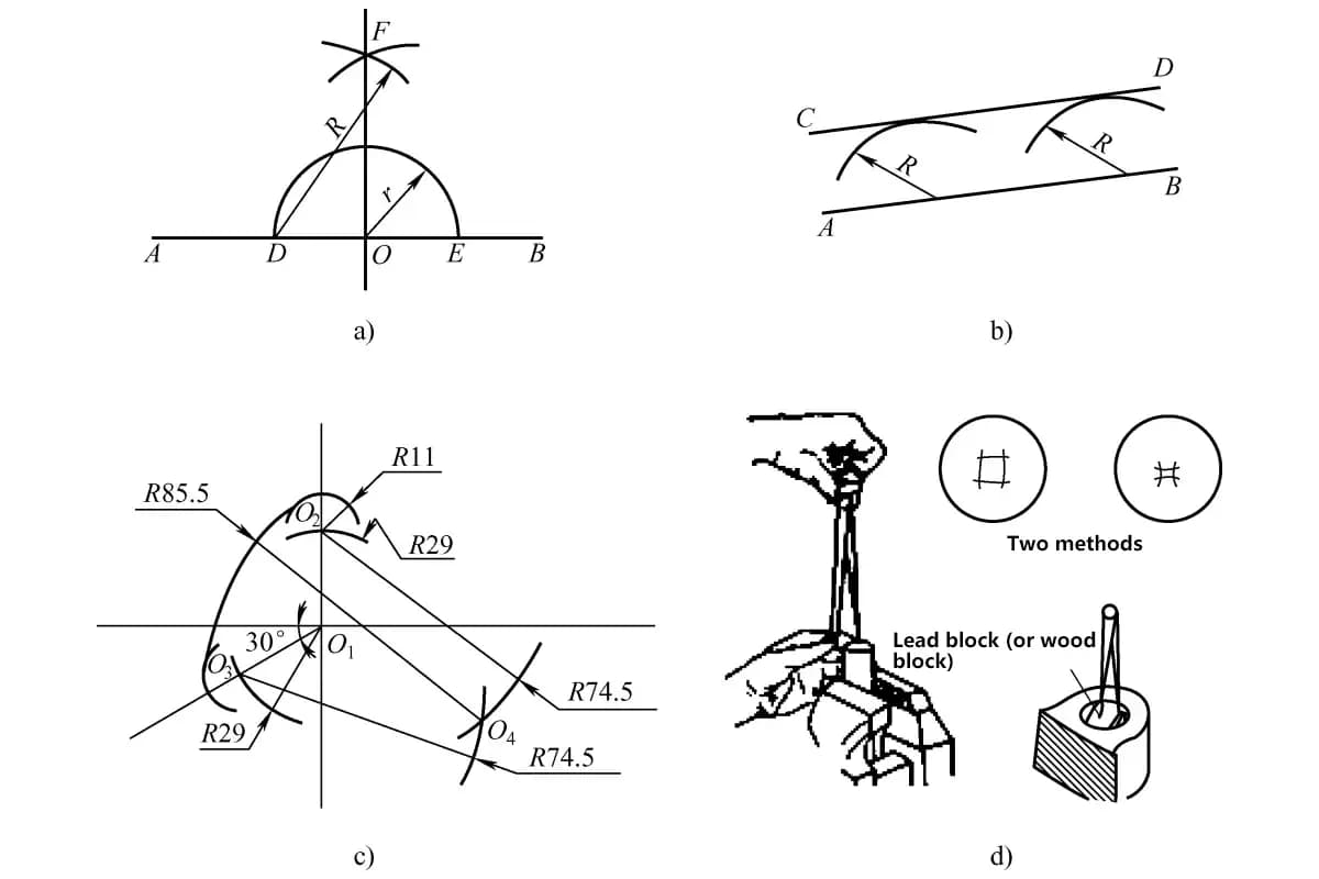
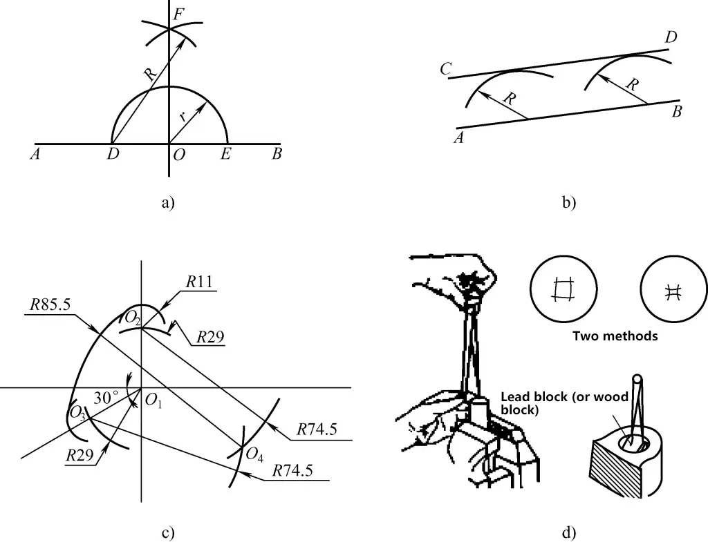
Basic marking methods refer to operations using marking tools to draw parallel lines, perpendicular lines, bisecting lines, arcs, arc connection lines, and finding centers on a certain surface of a part, as shown in Figure 8.
a) Drawing perpendicular lines
b) Drawing parallel lines
c) Drawing arc connection lines
d) Finding center using a center square
(2) Template marking
Template marking involves making templates based on drawings or actual objects and then marking according to the templates, as shown in Figure 9.
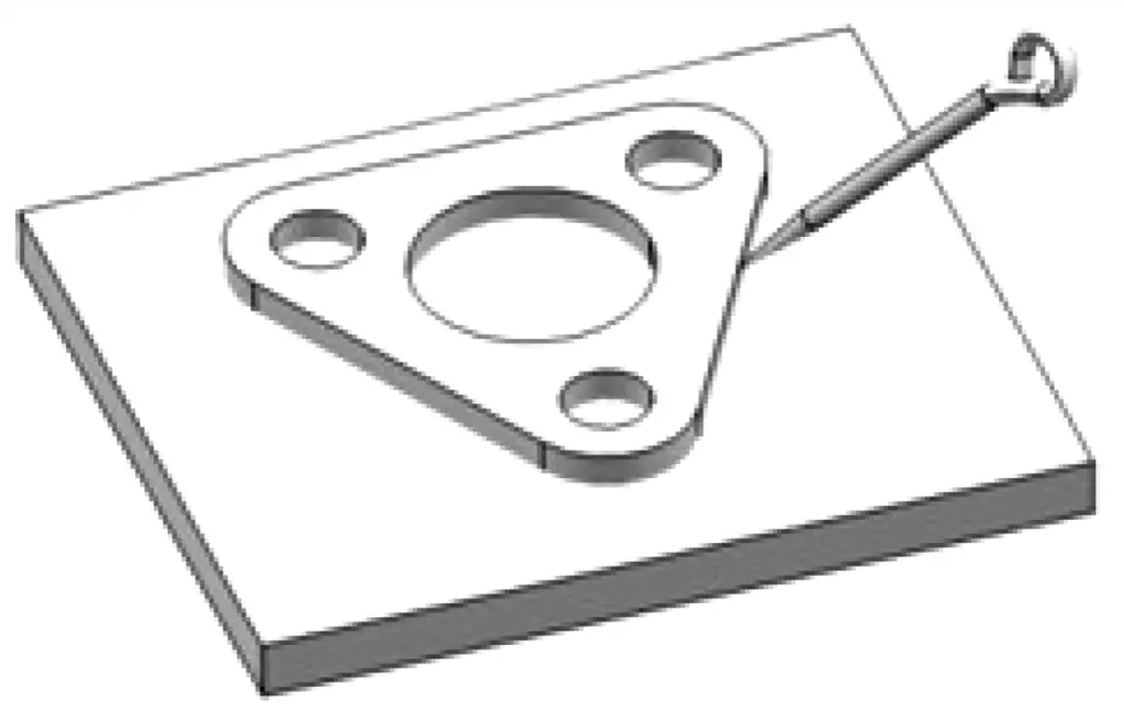
(3) Matching marking
Matching marking is a marking method based on already processed parts using a tracing method, such as marking complex-shaped gaskets, flanges, housings, or motor bases.
As shown in Figure 10, when processing bolt mounting holes on a flange mounting base (channel steel), first apply a layer of grease around the edge of the flange holes, then attach a thin paper to the mounting holes and press to create hole impressions. Next, apply a layer of red lead on the paper, and finally press the flange firmly onto the mounting channel steel in the selected installation position.
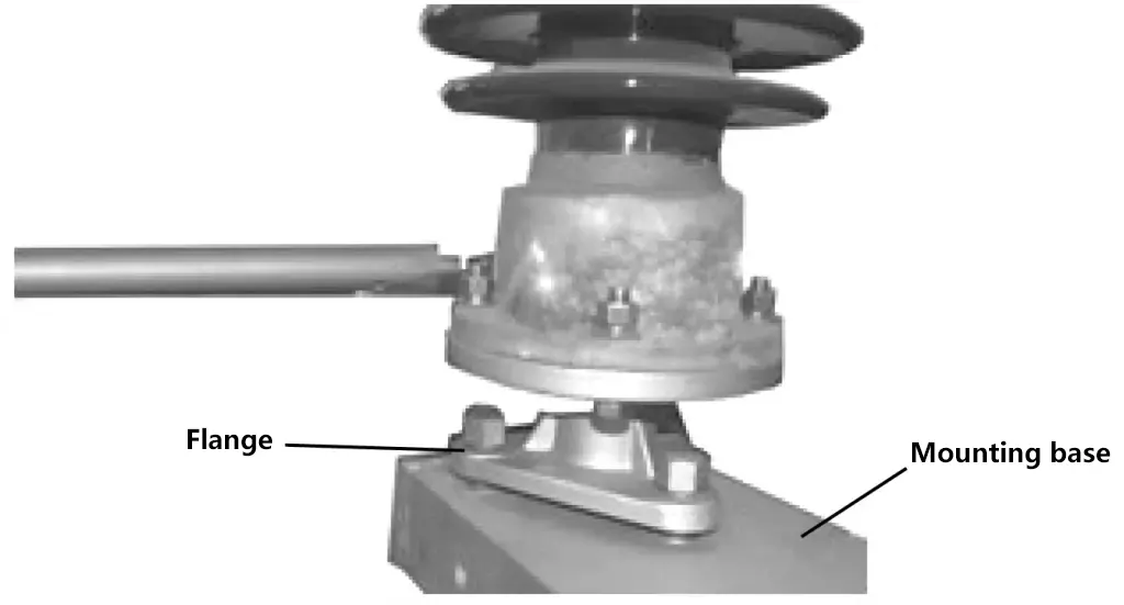
Due to the coloring effect of the red lead, the positions of the holes on the flange will be imprinted on the mounting channel steel. Then remove the flange, and drilling can be done according to the hole impressions.
(4) Copying marking
Copying marking, as the name suggests, is a method of marking by copying the original part. Its advantage is that it does not require measuring the original part, but instead directly places the original part and the part to be marked together, adjusts them, and then marks. Figure 11 shows a bearing housing, and its marking method belongs to copying marking.
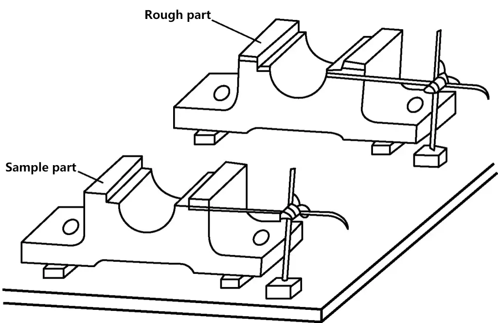
4. Marking steps and precautions
(1) Preparation work before marking
Before marking, preparatory work needs to be done. The main preparations before marking include cleaning and coloring of the workpiece.
1) Cleaning of the workpiece
The parts to be processed can be divided into two categories: one is rough castings, including cast and forged parts and various types of steel (angle steel, channel steel, steel plates, etc. used for bases or frames), and the other is mechanically processed or bench-worked parts.
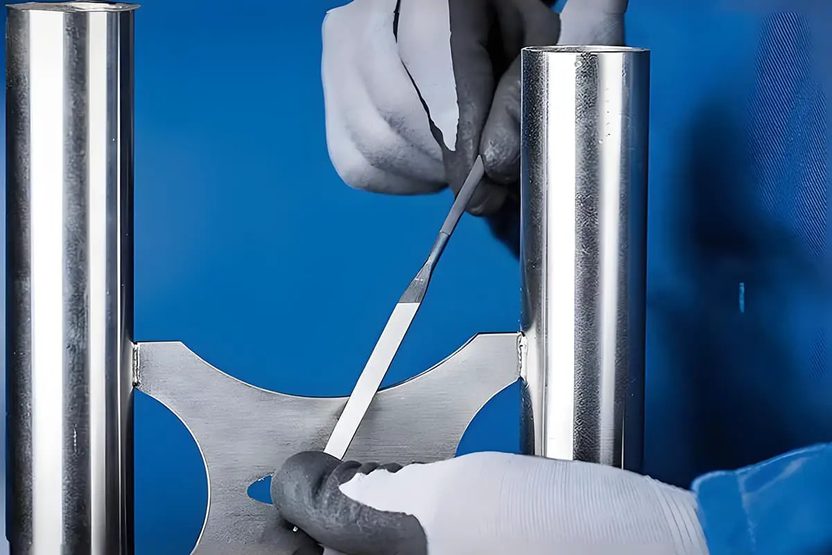
For rough castings, use hand grinders, angle grinders, wire brushes, old files, sandpaper, etc. to carefully clean the surface of scale, burrs, residual sand, dirt, etc. before coloring. For mechanically processed or bench-worked parts, if marking is needed on the processed surface, generally only filing to remove sharp burrs is required.
2) Coloring of the workpiece
To make the marked lines clearer, a layer of coating is generally applied to the marking area of the workpiece. Different coatings are used for rough castings and processed parts before marking, as listed below:
① For marking on cast or forged rough parts, lime water mixed with an appropriate amount of hide glue is generally used as the marking coating; for marking on various types of structural steel, lime water or white paint can be used as coatings, or chalk or stone pencils can be used to rub on the areas to be marked.
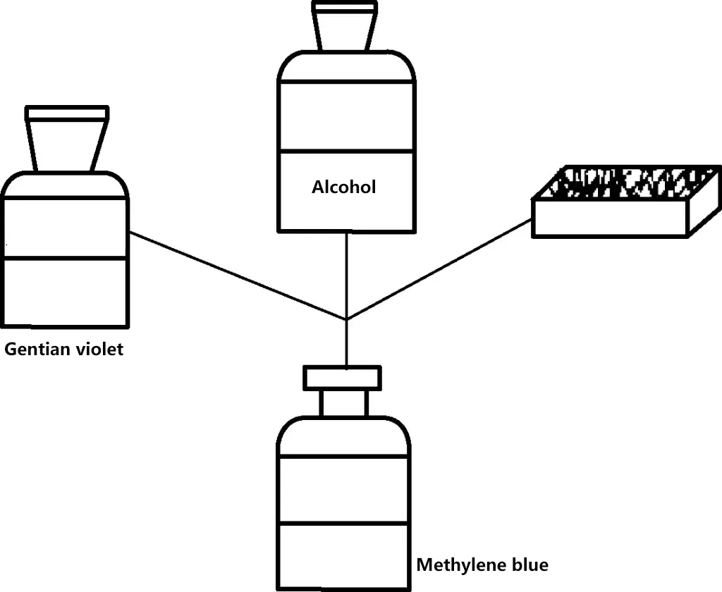
② Before marking on processed surfaces, blue layout dye is generally applied. The method for preparing blue layout dye is shown in Figure 12, with the composition (mass fraction) being 2%-4% gentian violet and blue dye, 3%-5% shellac and spirit varnish, and 91%-95% alcohol.
When coloring the workpiece, it should be applied as thin and evenly as possible. Only in this way can it ensure clearer line marking. If applied too thick, it is prone to peeling off.
3) Installing the center plug block
On cast parts, the cast holes are often very rough and need to be re-marked for machining. At this time, it is necessary to mark the hole position lines and hole shape lines (centering circles) for machining. Before marking the hole position lines and centering circles, it is first necessary to find the center of the original hole, so a center plug block (lead sheet block or wooden block, etc.) can be added to the original cast hole.
When using a wooden block, a piece of sheet metal can be nailed in advance at the position where the center is to be determined. Apply chalk or white paint, then use a scribing card to find the center and mark the circle, as shown in Figure 13.

(2) Layout work
- Analyze the drawing.
- Thoroughly understand the areas on the workpiece that need to be marked and their functions.
- Understand the processing requirements for the parts that need to be marked.
- Understand the positional relationships and dimensional connections between the areas that need to be marked.
- Determine the layout reference.
- Blank inspection. According to the drawing, use a steel ruler or scribing plate to check the bending, twisting, or warping errors of the blank; use a square to initially check its perpendicularity error; use calipers combined with a steel ruler to measure the dimensional errors of the blank, etc. If the errors are large, determine whether they can be salvaged through material borrowing methods and determine the borrowing plan.
- Correctly select layout tools, measuring tools, and auxiliary tools.
- Correctly position the workpiece.
- Layout.
- For three-dimensional layout, it is necessary to find the correct position and make trial markings.
- If significant defects are found in the blank, determine whether they can be salvaged through material borrowing methods. If remedial measures can be taken, determine the borrowing plan and carry out the borrowing operation.
- Formal layout.
- After positioning and aligning the workpiece in a certain orientation, try to mark all the position lines in this direction and carefully check for any missed lines.
- Re-check the accuracy of the layout, and if any deviations are found (see the previous layout requirements section), correct them promptly.
- After completing the layout, punch marks should be made on the marked surface of the blank for identification.
(3) Plane layout
Figure 14 shows a relatively complex motor liner part, with a thin plate thickness of 5mm. Before processing, all processing lines need to be marked. The layout steps are as follows:
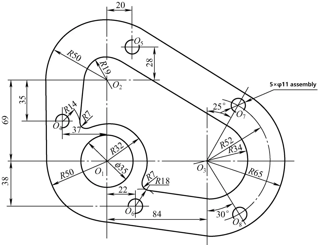
1) Select the size of the plate blank. According to the drawing dimensions, the maximum length dimension of the motor liner is: (50+84+65)mm=199mm, and the height dimension is (65+69+50)mm=184mm; the plate blank size that can be selected is: 210mm×200mm.
2) The layout steps are as follows:
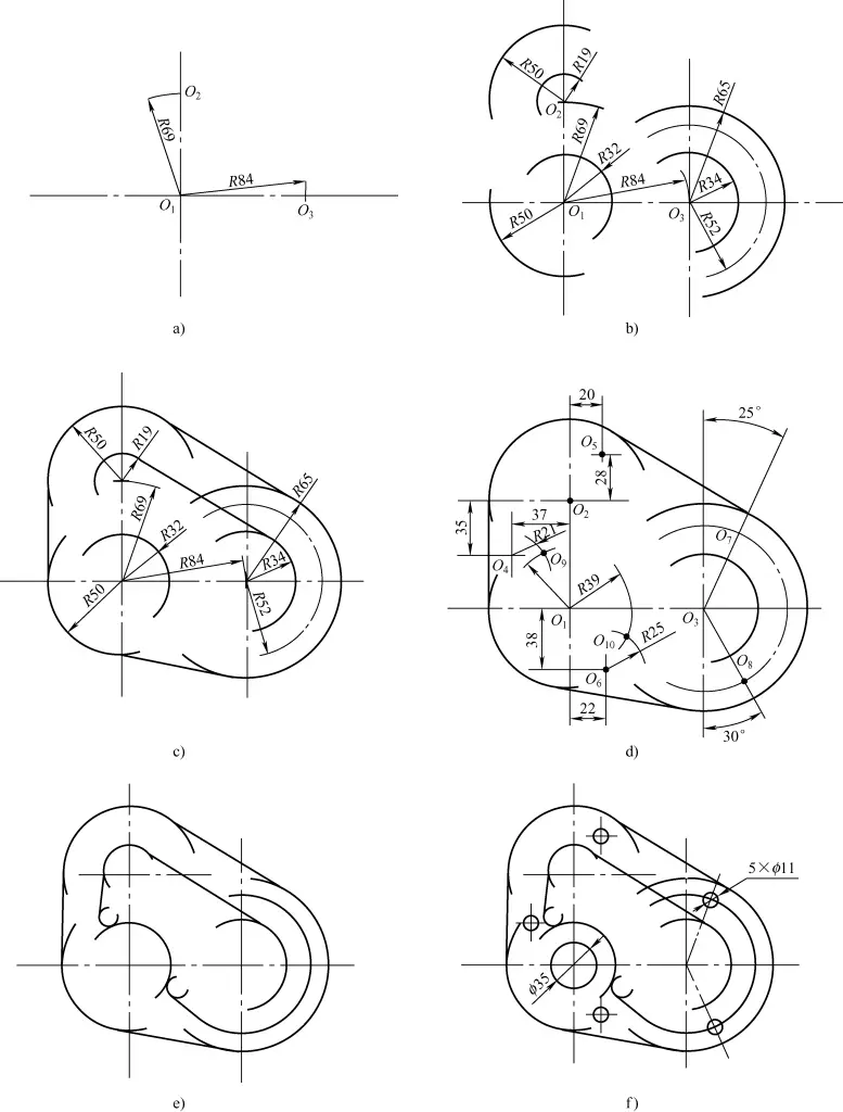
① According to the dimensions of the template figure, determine two perpendicular center lines in the lower left corner as the reference.
② Mark two perpendicular center lines with O1 as the center as the reference.
③ Draw a horizontal line with a dimension of 69mm to get the center O2, draw a vertical line with a dimension of 84mm to get the center O3, as shown in Figure 15a.
④ With O1 as the center, draw arcs with radii R32 and R50. With O2 as the center, draw arcs with radii R19 and R50. With O3 as the center, draw arcs with radii R34, R52, and R65, as shown in Figure 15b.
⑤ Draw common tangent lines to the outer arc and inner arc tangent lines parallel to the outer arc common tangent lines, as shown in Figure 15c.
⑥ Draw horizontal lines with dimensions of 38mm, 35mm, and 28mm.
⑦ Draw vertical lines with dimensions of 37mm, 20mm, and 22mm to get the centers O4, O5, and O6.
⑧ Find the centers of the two R7mm arcs, draw 25° and 30° angle lines through the center point O3 to get the centers O7 and O8, as shown in Figure 15d.
Note: Since the R32mm circle is externally tangent to the R7mm circle, arcs can be drawn with O1 and O4 as centers and R39mm as the radius; since the R14mm arc is externally tangent to the R7mm circle, an arc should be drawn with R21mm as the radius; R18mm is externally tangent to the R7mm circle, so an arc should be drawn with R25mm as the radius. Finally, the two R7mm circle centers O9 and O10 are obtained.
⑨ Draw tangent lines that are simultaneously tangent to the two R7mm arcs, R32mm, and two straight lines, as shown in Figure 15e.
⑩ Draw the ϕ35mm and five ϕ11mm hole circles, as shown in Figure 15f.
3) Check the lines according to the drawing to see if any are missing.
4) According to the requirements for punching marks, punch marks on the drawn lines.
(4) Three-dimensional layout (using bearing housing layout as an example)
Figure 16 shows the bearing housing part drawing. The precautions and steps for its three-dimensional layout operation are as follows:
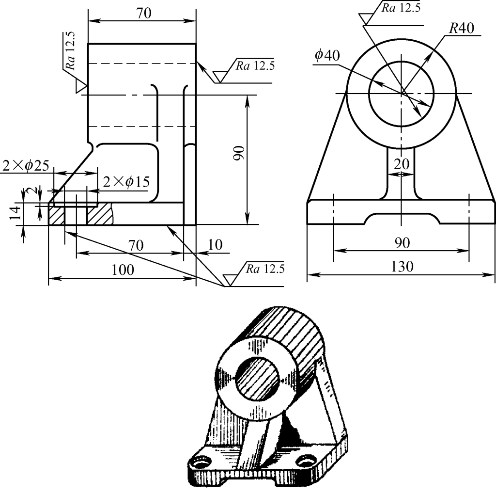
1) Precautions during layout operation
- The workpiece should be securely clamped to prevent slipping or movement.
- In one support, all parallel lines that need to be drawn should be marked to avoid errors caused by re-supporting and supplementary marking.
- Layout tools such as scribers, scribing plates, vernier height gauges, and squares should be used correctly to avoid errors.
2) Layout operation steps
① As shown in Figure 17, use the outer circle of the bearing housing (R40mm) as the reference circle, use a scribing card to center and mark the center range line of the bearing inner hole.
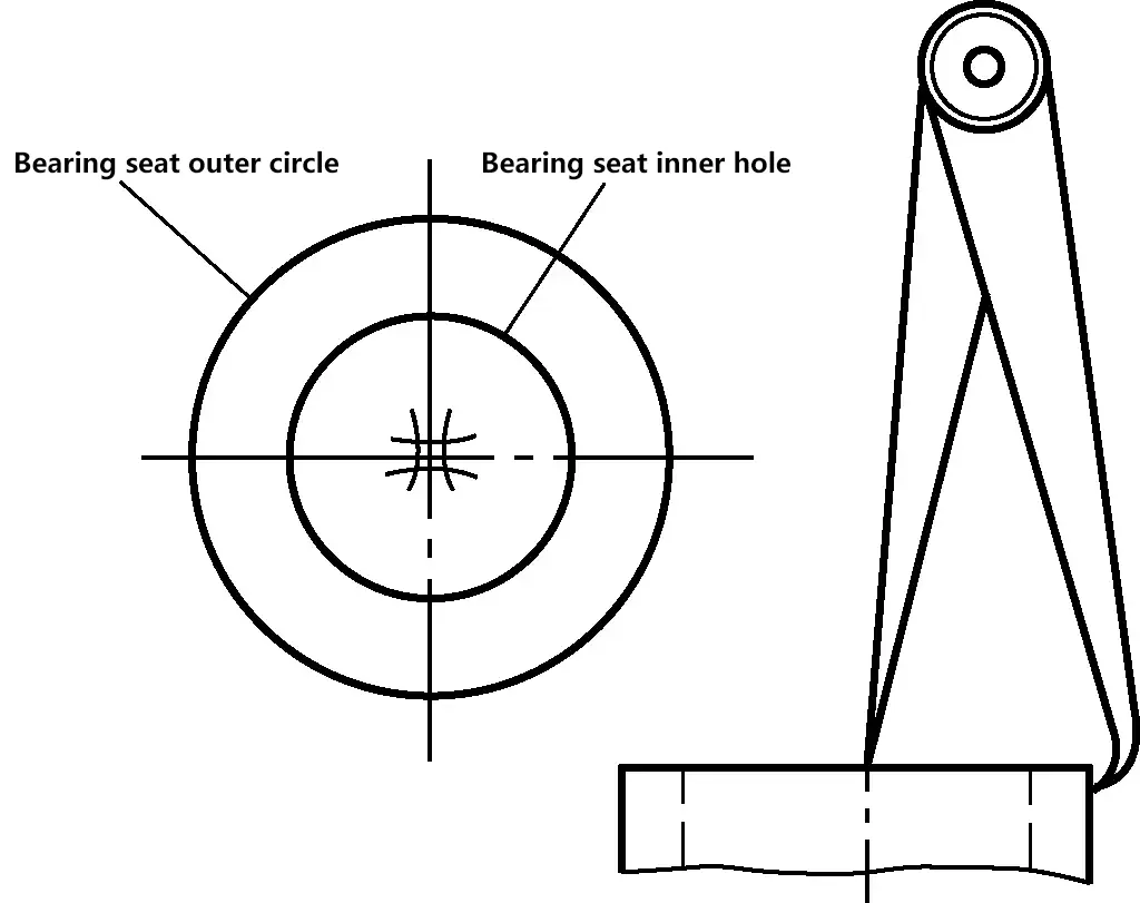
② Installation and alignment of the workpiece. As shown in Figure 18, adjust the height of the three jacks and use a scribing plate to level the unprocessed surface (the upper surface of the bearing housing base plate).
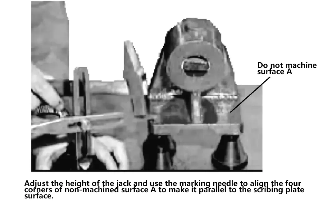
③ Height direction layout, steps are as follows:
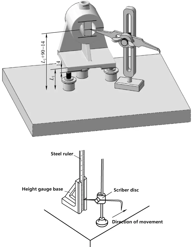
As shown in Figure 19, use a steel ruler or the curved tip of a scribing plate combined with a height gauge to measure dimension L1; use the straight foot tip of the scribing plate combined with the height gauge to measure dimension (L1+90mm-14mm), mark the center line of the bearing housing hole, add and subtract the inner hole radius (referring to the steel ruler) to measure the dimension, and mark the upper and lower inner circle tangent lines of the housing hole (ϕ40mm).
Use the straight foot tip of the scribing plate combined with the height gauge to measure dimension (L1-14mm), mark the processing line for the mounting surface at the bottom of the bearing housing. Similarly, mark the height line for the oil filling hole end face.
Observe whether the center line in the height direction of the bearing inner hole is within the center range found by the scribing card in the above steps. If it is within the “well” shaped center arc range, no material borrowing is needed; if it is not within the “well” shaped center arc range, then height direction material borrowing should be performed, that is, material can be borrowed by adjusting the machining allowance in the height direction of the inner and outer circles of the bearing housing, with specific borrowing methods as described earlier.
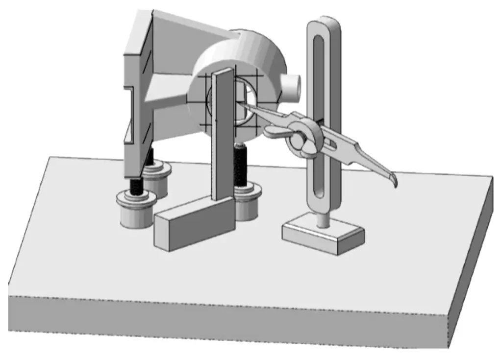
④ Length direction layout. Rotate the bearing housing 90°, support it well with three jacks, adjust the jacks, and use a square to check the verticality, as shown in Figure 3-19.
- As shown in Figure 20, similar to marking the processing lines in the height direction, use the straight foot tip of the scribing plate to mark the center axis in the length direction. Refer to the hole center line height data on the height gauge, add and subtract the hole radius, then use the straight foot tip to measure the dimension on the height gauge and mark the upper and lower inner hole circle tangent lines.
- Adjust the straight foot tip of the scribing plate to the correct dimension and mark the processing line for the mounting bottom surface in the length direction of the bearing housing.
- Adjust the straight foot tip of the scribing plate to the correct dimension and mark the processing line for the mounting holes on the bottom surface in the length direction of the bearing housing.
- Observe whether the center line in the length direction of the bearing inner hole is within the center range found by the scribing card in the above steps. If it is within the “well” shaped center arc range, no material borrowing is needed; if it is not within the “well” shaped center arc range, then length direction material borrowing should be performed, that is, material can be borrowed by adjusting the machining allowance in the length direction of the inner and outer circles of the bearing housing, with specific borrowing methods as described earlier.
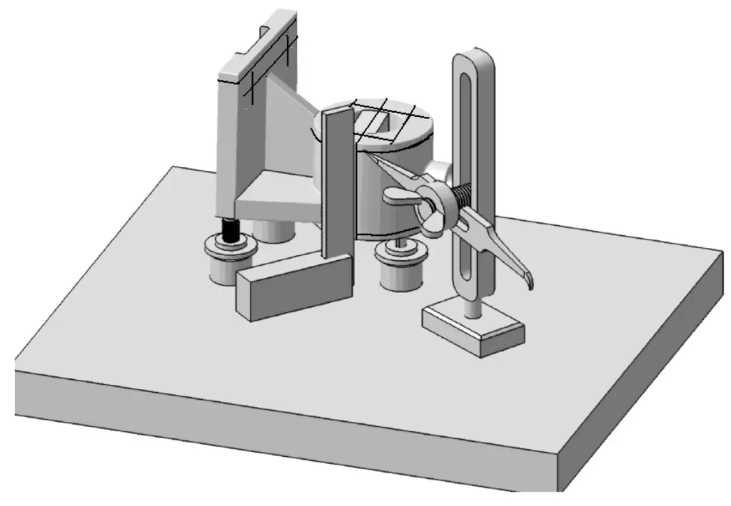
⑤ Width direction layout. As shown in Figure 21, rotate the bearing housing another 90° and position it, adjust the height of the jacks, and use a square to check verticality. Mark the processing lines for the bearing housing hole end face, the mounting holes on the bottom surface in the width direction, and the mounting bottom surface in the width direction.
⑥ After completing the layout and checking for errors, punch marks on the drawn lines. At this point, the layout is complete.
5. Dividing head layout
(1) Division formula
If you want to divide the workpiece into z equal parts, each time the workpiece (spindle) needs to rotate 1/z turn, the number of turns of the dividing head handle should be n turns, and they should satisfy the following relationship (z<40), namely
n=40/z=a+P/Q
Where n is the number of turns the dividing head should make when dividing into z equal parts; z is the number of divisions of the workpiece; 40 is the constant of the dividing head; a is the whole number of turns of the dividing handle; Q is the number of holes in a certain hole circle on the dividing plate; P is the number of hole spacings the handle should move on the hole circle with Q holes.
It can be seen that by turning the dividing handle 40/z turns, the spindle can be rotated 1/z turn.
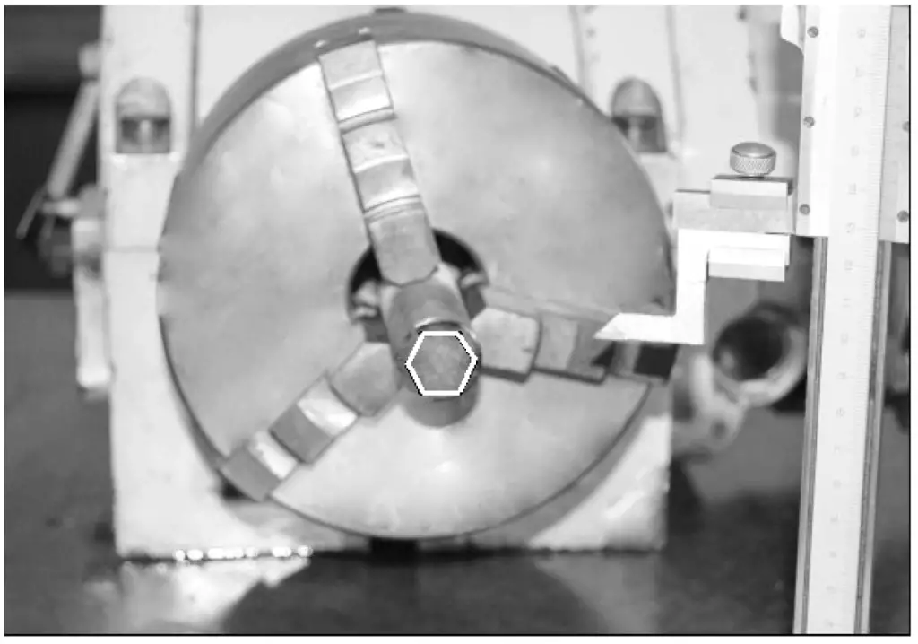
As shown in Figure 22, to divide a cylinder into six equal parts (i.e., to mark the processing boundaries of a regular hexagonal prism on the end face and outer cylindrical surface), for each line drawn, the dividing head handle should turn n=40/6=(6+2/3) turns. That is, every time the dividing head turns (6+2/3) turns, one line can be drawn. By turning the handle in this way, the hexagon can be marked on the end face of the cylinder.
But the question is how to turn 2/3 of a turn? The following detailed analysis addresses this issue.
(2) Division methods
1) Simple division method
As shown in Figure 22, simple division can be performed using the graduated dial. For example, to mark the processing boundaries of a regular hexagonal prism on the end face and outer cylindrical surface of a cylinder, turn the handle 60° each time and use a height gauge to draw a line.
2) Precise division layout
For precise equal division, the dividing plate can be used for division layout.
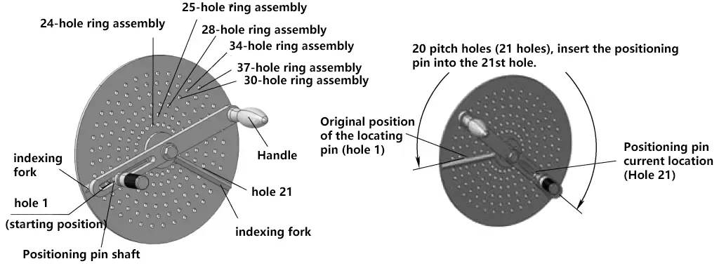
As shown in the dividing plate in Figure 23, it is the basis for division counting. There are several circles of holes on the dividing plate with different numbers of holes that are accurately divided. When the calculated n value includes a fraction, the denominator and numerator of this fraction can be multiplied by the same factor to make the denominator equal to the number of holes in a certain circle on the dividing plate, and the numerator becomes the number of hole spacings the handle should move.
For example, for the 2/3 turn in the above example, the denominator and numerator can both be multiplied by 8, changing it to 16/24, and 24 holes is exactly one group of hole circles on the dividing plate. Therefore, by moving the dividing handle 16 hole spacings (17 holes) on the 24-hole circle group, the purpose of turning 2/3 of a turn can be achieved.
In other words, after turning 6 full turns and 16 hole spacings (17 holes), one line can be drawn. By turning the handle
In other words, a line can be drawn after every 6 rotations and 20 hole spaces (21 holes). Similarly, the numerator and denominator can be simultaneously expanded to other multiples. Experience shows that the more holes in a hole circle group, the higher the indexing precision. The specific indexing process is shown in Figure 23.
