I. Fundamentals of Machine Tool Cutting
The main mechanical processing methods include turning, planing, grinding, milling, boring, drilling, shaping, etc. Machine tools cut workpieces using cutting tools, so they must have clamping tools and cutting tools, as well as the ability to perform working movements.
1. Machine Tool Cutting Movements
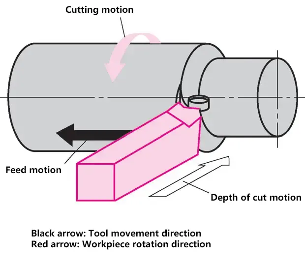
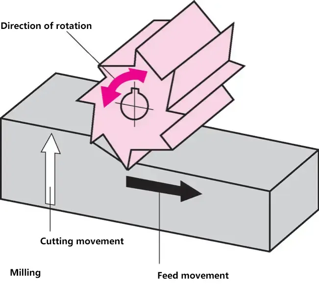
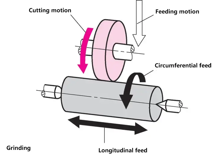
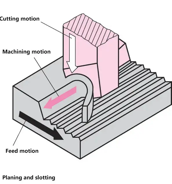
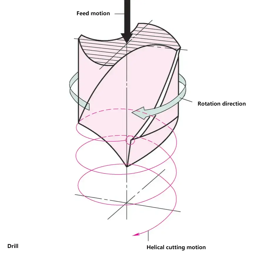
The relative motion between the cutting tool and the workpiece is the condition for cutting. The main working movements include the primary motion and the feed motion.
(1) Primary Motion
The working movement that completes the cutting. The primary motion can be in the form of rotational movement or reciprocating linear movement (performed by either the workpiece or the cutting tool). For turning, grinding, milling, and drilling operations, the primary motion is rotational.
(2) Feed Motion
The motion provided by the machine tool or manual power, which creates additional relative movement between the cutting tool and the workpiece. Combined with the primary motion, it allows for continuous or intermittent cutting of the workpiece. When the primary motion is rotational, the feed motion is continuous, as in turning, drilling, and milling; when the primary motion is linear, the feed motion is intermittent, as in planing and shaping. The depth of cut depends on the feed motion.
(3) Cutting Depth Motion
Determines the depth of cut, manifested as the tool penetrating the workpiece.
(4) Machining Motion
In turning, drilling, milling, and grinding, when the primary motion and feed motion occur simultaneously, the resulting combined motion is called the machining motion.
2. Cutting Tool Geometry
The wedge-shaped cutting edge of the tool penetrates the workpiece material, separating the chip from the material. The main factors affecting cutting are the tool geometry, tool material, and workpiece material. The sharpness of the tool is determined by its shape, which is defined by various angles of the tool.
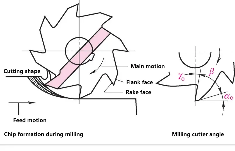
(1) Wedge Angle β
The angle between the front face and the main back face. When the wedge angle of the tool is small, the tool is sharp and easy to cut, but it is prone to edge chipping when cutting hard materials.
- For cutting soft metals: βo=40°~50°, such as aluminum.
- For cutting highly ductile metals: βo=55°~75°, such as 42 steel.
- For cutting hard and brittle metals: βo=75°~85°, such as bronze, castings, etc.
(2) Rake Angle γo
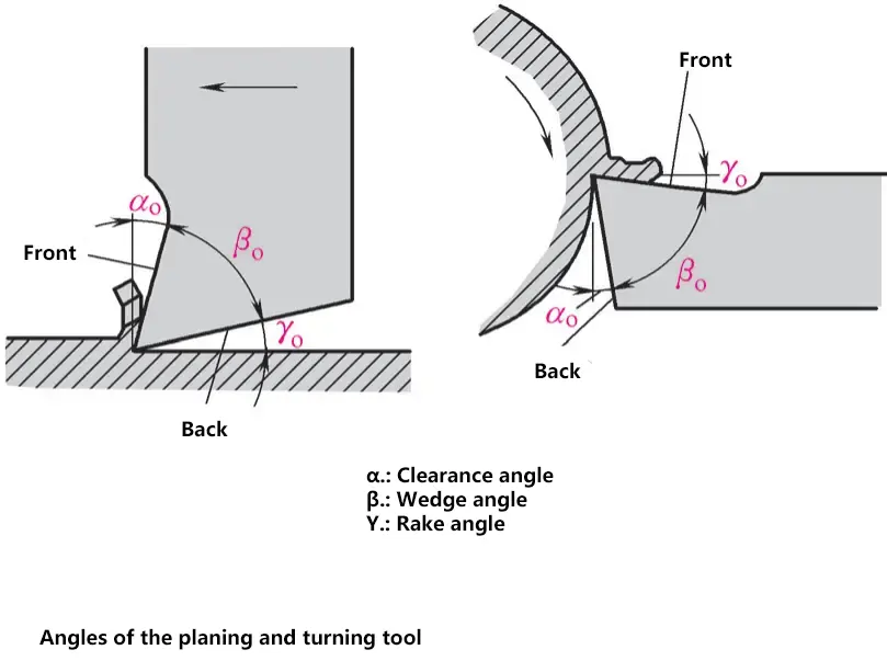
Affects chip formation and cutting force. The rake angle range is -5° to 30°, and its size is determined by the workpiece material and tool material.
When the rake angle is large, chips flow easily, and cutting force is small. When the rake angle γo is small or even negative, the cutting force is large, and the cutting edge strength is high.
(3) Relief Angle αo
Can reduce friction between the tool and the workpiece. The relief angle range is 5° to 12°.
The softer the workpiece material, the larger the workpiece diameter and depth of cut, the relief angle αo increases accordingly; the larger the relief angle αo, the rougher the machined surface.
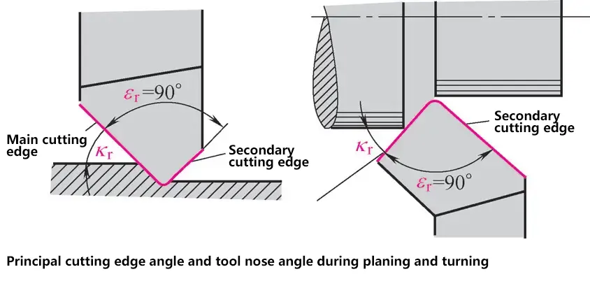
(4) Tool Nose Angle εr
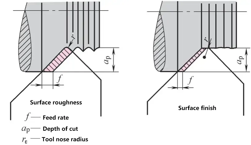
- When the feed rate is high: Thick chips, high cutting efficiency
When the tool tip radius is small: Deep tool marks on the workpiece surface - When the feed rate is low: Thin chips, low cutting efficiency
When the tool tip radius is large: Shallow tool marks on the workpiece surface
The angle between the projections of the main cutting edge and the secondary cutting edge on the base plane. A large tool nose angle results in greater heat dissipation because the tool’s external heat dissipation area is larger. The cutting edge generates less heat and is less likely to become dull, thus extending tool life. Tool life refers to the time interval between two tool sharpenings.
When feed is small (≤ 1mm/r), ε=90°; when feed is large (> 1mm/r), ε > 90°.
(5) Entering Angle Kr
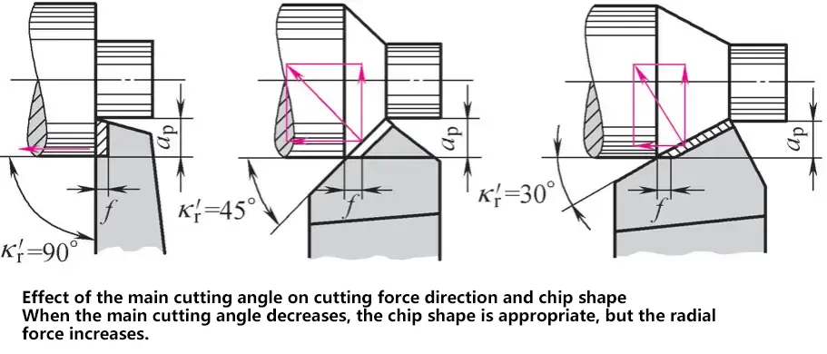
The entering angle affects the direction of cutting force and chip shape. When the entering angle is reduced, the chip shape is more suitable, but the radial force increases.
The angle between the main cutting edge and the feed direction. It affects the decomposition of cutting forces, chip shape, and tool life. The entering angle kr can be chosen in the range of 30° to 90°, with the most advantageous Kr=45°.
(6) Inclination Angle λs
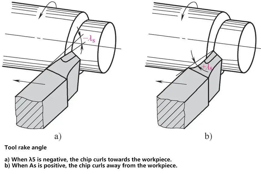
a) When λs is negative, the chip curls towards the workpiece
b) When λs is positive, the chip curls away from the workpiece
The angle between the main cutting edge and the base plane. When the tool tip is the lowest point on the main cutting edge, the inclination angle is defined as negative; when the tool tip is the highest point on the main cutting edge, the inclination angle is positive.
For higher loads, the inclination angle is larger, ranging from -10° to 10°.
3. Chip Formation
The chip cross-sectional area is the product of the depth of cut ap and the feed rate f. The chip shape depends on the entering angle κ, while the depth of cut is related to the workpiece shape and dimensions.
Before the chip is separated, the cutting edge first penetrates the material in front, causing cracks. The cutting edge continues to penetrate until the chip is separated due to the wedging action of the cutting edge.
(1) Fragmented Chips
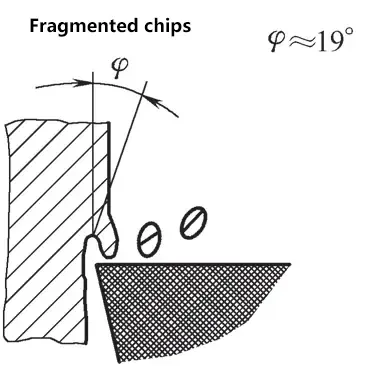
During cutting, fragmented chips are produced, and the chips are discontinuous; the machined workpiece surface is uneven.
(2) Segmented Chips
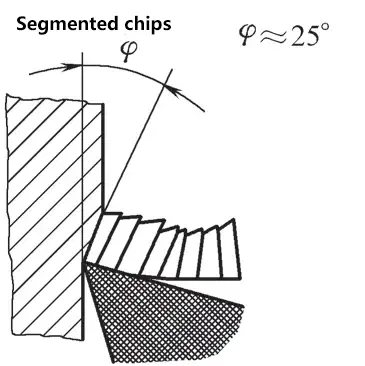
The separated chips are in the form of segments. These segmented chips are partially welded together to form a continuous chip.
(3) Continuous Chips
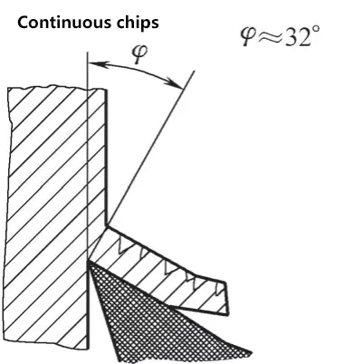
The material flows in the cutting zone when being separated; there is no fracture in the material, resulting in a continuous chip.
Built-up Edge: When cutting softer and more ductile materials, undesirable adherence forms on the cutting edge, known as a “built-up edge.” This results in a rough machined surface and deep tool marks. Material particles momentarily adhere to the cutting edge, forming the built-up edge. The built-up edge embeds into the cracks in front of the tool on the workpiece, and when it detaches, it leaves impressions on the workpiece surface. Built-up edge can be avoided by increasing cutting speed, increasing depth of cut, and grinding the tool’s front face.
4. Cutting Fluids
During the cutting process, proper use of cutting fluids can reduce temperature in the cutting zone, improve surface quality and accuracy, and extend tool life.
(1) Functions of Cutting Fluids
1) Cooling
After the cutting fluid is applied to the cutting area, it dissipates heat from the chips, tool, and workpiece through heat conduction, convection, and vaporization of the cutting fluid, thus providing a cooling effect.
2) Lubrication
The cutting fluid penetrates between the contact surfaces of the chip, tool, and workpiece, forming a lubricating film on the metal surface to reduce the friction coefficient and suppress built-up edge formation, thereby improving the quality of the machined surface and extending tool life.
3) Cleaning
The cutting fluid washes away fine chips or abrasive powder produced during the cutting process, thus cleaning and preventing scratches on the machined surface and machine tool guide ways.
4) Rust Prevention
By adding rust-inhibiting additives to the cutting fluid, a protective film can be formed on the metal surface, protecting the machine tool, workpiece, and cutting tool from corrosion by the surrounding media.
(2) Selection of Cutting Fluids
Common cutting fluids include aqueous solutions, emulsions, and cutting oils.
- Aqueous solutions are cutting fluids with water as the main component and added rust-inhibiting additives, primarily used for cooling.
- Emulsions are widely used cutting fluids in machining processes. They are mixtures of oil and water, with added emulsifiers such as fatty acids, sodium soaps, and potassium soaps.
- Cutting oils mainly provide lubrication and include total loss system oils, light diesel oil, and kerosene.
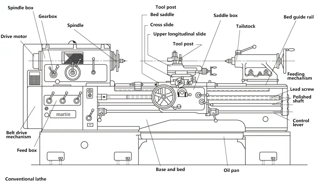
II. Turning
The horizontal lathe is a widely used universal machine tool that can perform various turning operations. Various specialized lathes are suitable for mass production; some are suitable for machining very large workpieces; some for machining very small workpieces; and some for special process machining.
1. Fundamentals of Turning
(1) Overview
Turning is a cutting method that uses the rotation of the workpiece and the movement of the cutting tool on a lathe to machine various rotational surfaces. The characteristics of turning include machining rotational parts, processing metal materials, as well as non-metallic materials such as wood, plastic, rubber, and nylon. Turning can achieve dimensional accuracy of IT6 to IT11 and surface roughness values of Ra0.1 to 12.5μm.
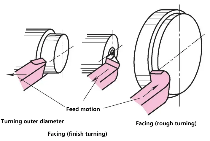
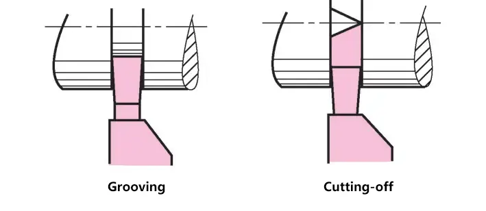
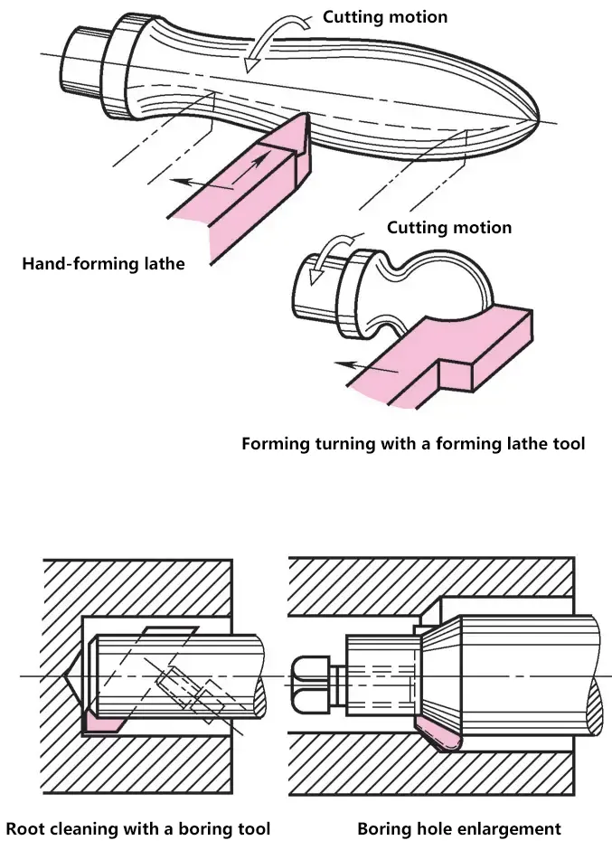
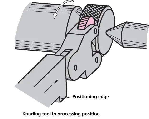
Turning has a wide range of applications, including machining external cylinders, drilling center holes, grooving, threading, facing, boring, turning tapers, knurling, and machining disc springs. With appropriate fixtures and attachments, lathes can also perform grinding, polishing, burnishing, broaching, and milling of flat surfaces, as well as machining other special and complex parts with internal and external cylindrical surfaces.
(2) Main Cutting Parameters
The relative motion between the cutting tool and the workpiece during metal cutting is called the cutting motion. The cutting motion is divided into primary motion and feed motion. The motion that directly removes the layer being cut from the workpiece and turns it into chips is called the primary motion; the motion that ensures the layer being cut is continuously or intermittently fed into the cutting process to gradually machine the entire workpiece surface is called the feed motion.
During the cutting process, the workpiece surface is divided into the surface to be machined, the transition surface, and the machined surface. The three surfaces in external cylindrical turning are shown in the figure.
To obtain the desired machined surface, improve machining efficiency, and reduce machining costs, it is necessary to select appropriate cutting parameters, including cutting speed, feed rate, and depth of cut.

1) Cutting speed vc. The instantaneous velocity of a selected point on the cutting edge relative to the workpiece’s primary motion, namely
vc=πdwn/100
Where
- vc-cutting speed (m/min);
- dw-diameter of the selected point on the cutting edge (or tool) (mm);
- n——lathe spindle speed (r/min).
2) Feed rate f. The displacement of the tool relative to the workpiece in the feed direction, in turning, the feed rate is expressed as the movement of the tool per revolution of the lathe spindle (mm/r).
3) Depth of cut ap. The depth of cut measured in the direction perpendicular to the working plane and passing through the base point of the cutting edge, namely
ap=(dw-dm)/2
Where
- ap-depth of cut (mm);
- dw-diameter of the workpiece surface to be machined (mm);
- dm-diameter of the machined workpiece surface (mm).
2. Turning Tools
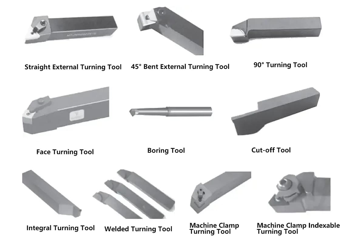
Various turning tools are used in turning operations, which can be classified by purpose into straight external turning tools, 45° bent external turning tools, 90° turning tools, face turning tools, boring tools, parting tools, etc. According to structure, they can be classified as integral turning tools, welded turning tools, mechanically clamped turning tools, mechanically clamped indexable turning tools, etc.
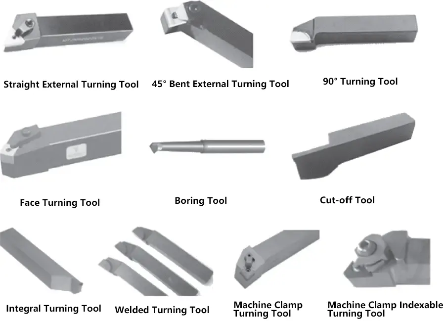
A turning tool consists of a cutting head that performs the cutting task and a tool shank, with the cutting part composed of three faces, two edges, and one point.
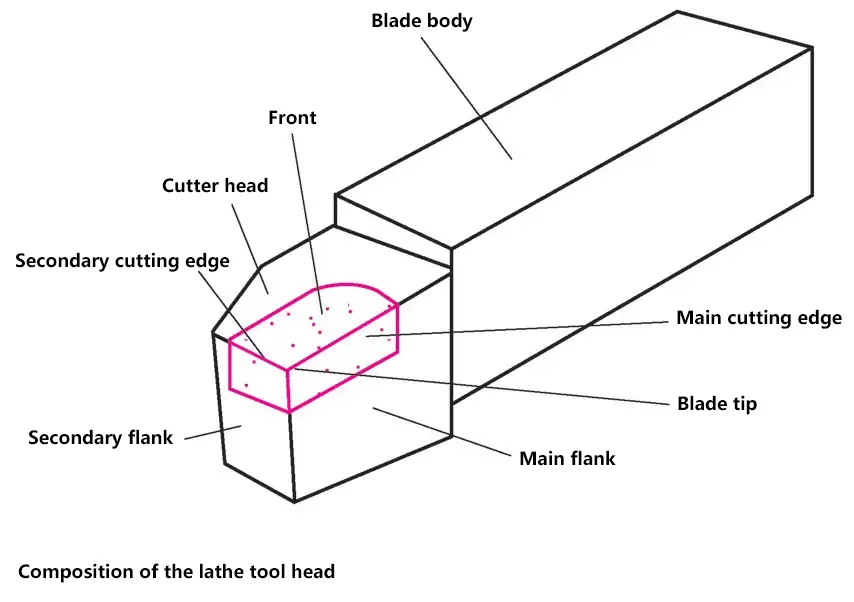
(1) Rake face
The surface of the tool over which the chip flows.
(2) Main flank
The back face of the tool that intersects with the rake face to form the main cutting edge.
(3) Secondary flank
The back face of the tool that intersects with the rake face to form the secondary cutting edge.
(4) Main cutting edge
For turning tools, it is the intersection line of the rake face and the main flank, which performs the main cutting task.
(5) Secondary cutting edge
For turning tools, it is the intersection line of the rake face and the secondary flank, which participates in partial cutting work.
(6) Tool tip
A small portion of the cutting edge at the junction of the main and secondary cutting edges. To increase the strength of the tool tip, it is usually ground into a small transitional arc.
3. Workpiece Clamping
The choice of clamping tools depends on the shape, size, quantity, and quality requirements of the workpiece. The workpiece fixture must transmit rotational motion to the workpiece and be able to fully withstand the reaction forces generated during cutting.
(1) Self-centering chuck
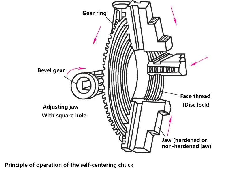
Self-centering chucks are used for clamping workpieces with circular, triangular, and hexagonal cross-sections.
When the chuck wrench is turned to rotate the bevel gear, it creates a clamping motion of the jaws, which can clamp from the outside towards the inside. The steps on the jaws can expand the clamping range. When clamping long bar stock, it can be extended into the hollow spindle.
(2) Independent chuck
Used for clamping square and octagonal workpieces.
(3) Centers
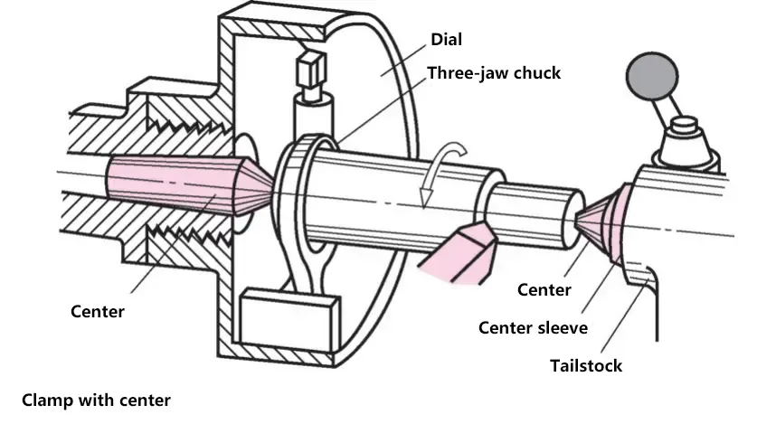
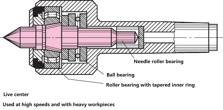
If the workpiece is completely circular and frequently needs to be re-clamped, it should be clamped between left and right centers. A drive plate and a dog transmit the rotational motion to the workpiece. To reduce contact surface pressure and avoid damaging the centers, they can be made as live centers.
(4) Steady rest
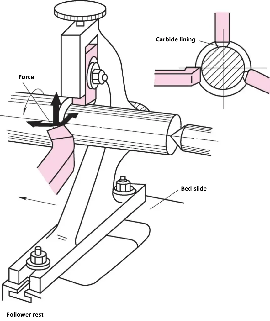
A steady rest is used to support long workpieces to prevent deflection and deformation during machining. It is also used when machining the end face of long workpieces. The steady rest is fixed on the sliding guide of the lathe bed. Good roundness of the workpiece is a condition for using support jaws. To prevent seizing between the support jaws and the workpiece, the jaws should be made of hardened steel, bronze, carbide, or plastic inserts.
(5) Mandrel
A mandrel is used when high concentricity between the hole and the outer diameter of the workpiece is required.
(6) Fixed mandrel
The diameter is the same as the hole diameter of the workpiece. The mandrel has a very small taper of 1:400 after hardening and grinding, so it can generate a large clamping force.
(7) Expanding mandrel
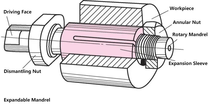
A cylindrical clamping sleeve with a conical inner surface and three slots on the side is fitted onto a conical rotating mandrel using a ring nut. The clamping sleeve expands, clamping the workpiece’s inner hole from the inside out. The expanding mandrel is clamped between centers at both ends.
(8) Collet chuck
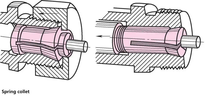
Used for clamping short, small-diameter cylindrical workpieces. Clamping is quick, precise, and secure.
The front of the collet has a reverse taper and three slots. It can be pressed into the spindle’s tapered hole using an outer nut or pulled into the spindle’s tapered hole using a clamping lever that passes through the hollow spindle. However, only polished, deburred, and properly sized cylindrical workpieces clamped inside can ensure no radial runout.
(9) Face plate
Face plates are used for clamping large-diameter or asymmetrically shaped workpieces. The face plate has four independently adjustable jaws. The jaws can be rotated 180°, serving as both internal and external jaws.
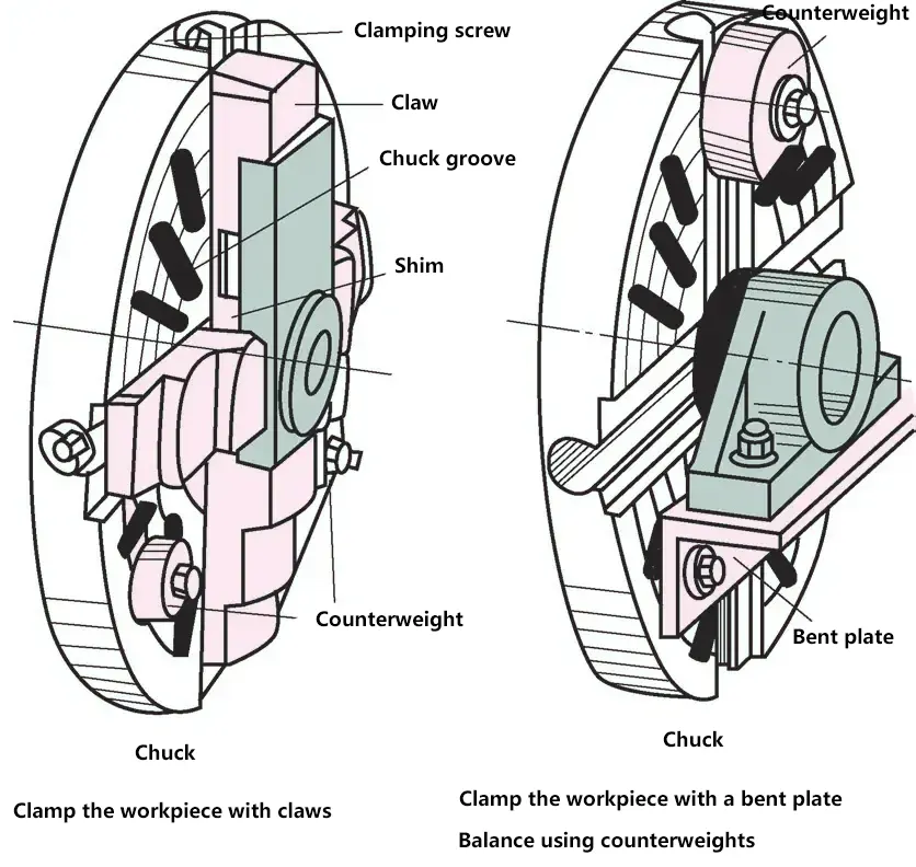
When clamping a workpiece, first visually align it, then use a marking dial to center the workpiece. If higher machining accuracy is required, use a dial indicator to center the workpiece. Because the face plate has several radial slots, screws, clamps, or bent plates can also be used to clamp the workpiece.
III. Grinding
1. Grinding wheel
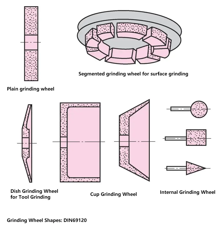
A grinding wheel is composed of abrasive grains and bonding material, with a specific shape. When the grinding wheel rotates at high speed, the abrasive grains come into contact with the workpiece to perform cutting.
Dull abrasive grains fracture and form new sharp grains (cutting edges) on the fractured surfaces.
Grinding wheels mainly come in flat, single-side concave, cylindrical, bowl-shaped, dish-shaped, and double-bevel shapes to suit grinding surfaces of different shapes and sizes.
(1) Structure of the grinding wheel
A grinding wheel consists of abrasive (the material forming the abrasive grains in the wheel), grit size (coarseness of the abrasive grains), (bonding strength), structure (porosity of the wheel), and bonding agent (the material that binds the abrasive grains together).
(2) Mounting the grinding wheel
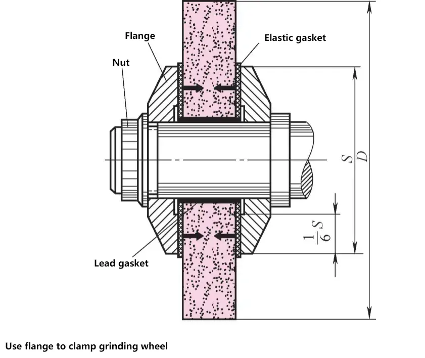
Before installing the grinding wheel, it needs to be suspended and subjected to a sound check (lightly tapping the wheel should produce a clear sound without any odd noises). Then it is clamped with flanges made of gray cast iron, steel, or similar materials. Next, a guard made of tough materials (steel, cast steel, etc.) is installed. Due to the high rotational speed, the installed grinding wheel must undergo static and dynamic balance checks and adjustments.
2. Grinding process
(1) Surface grinding
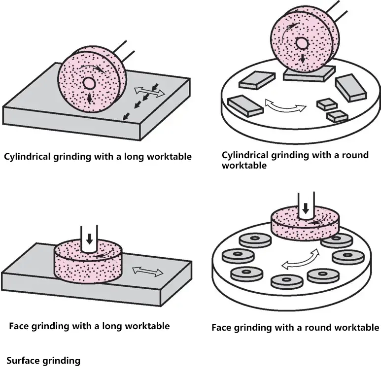
Based on the position of the grinding wheel axis, surface grinding is divided into peripheral grinding (horizontal wheel axis) and face grinding (vertical wheel axis). Grinding machines have either a long worktable that moves back and forth or a circular worktable that rotates.
Grinding can be divided into three stages:
1) Rough grinding.
Large material removal, improving workpiece shape, removing machining marks. Wheel grit size F40 to F60, depth of cut 0.010 to 0.030mm.
2) Semi-finish grinding.
Improving surface quality, dimensional accuracy can reach IT5. Wheel grit size F80 to F100, depth of cut 0.005 to 0.015mm.
3) Finish grinding.
Further improving surface quality, dimensional accuracy can reach IT3 to IT4. Wheel grit size F220 to F320, depth of cut 0.001 to 0.008mm.
Grinding allowance is between 0.1 to 0.6mm depending on the workpiece size.
(2) Cylindrical grinding
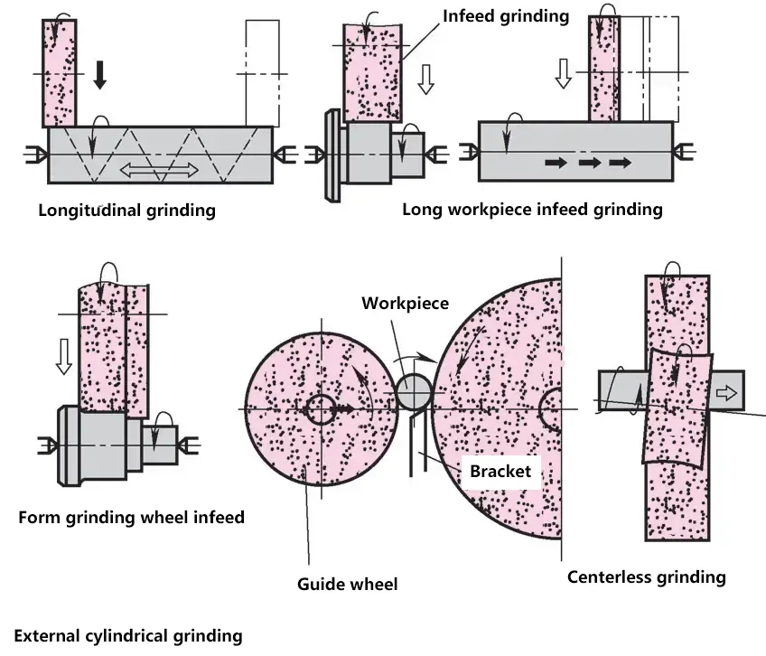
The workpiece rotates at a low speed. This motion is the feed motion and can be either in the same direction as the grinding wheel rotation or opposite to it. Based on the auxiliary motion, it can be classified as:
- Traverse grinding. The workpiece rotates and moves axially.
- Plunge grinding. The grinding wheel moves radially towards the workpiece.
- Plunge grinding of long workpieces. After each plunge, the workpiece moves axially by less than the width of the grinding wheel.
- Plunge grinding with a formed wheel. In this type of grinding, the difference in diameters should not be too large.
- Centerless grinding. The workpiece is placed between the grinding wheel and a regulating wheel without being clamped. The grinding wheel grinds the workpiece at a relatively high speed.
(3) Internal grinding
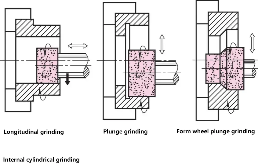
Hole grinding is generally done using traverse grinding and plunge grinding. To ensure that the contact area between the grinding wheel and the workpiece is not too large, the maximum diameter of the grinding wheel should not exceed 2/3 of the hole diameter. The challenges in internal grinding are temperature rise and poor chip removal conditions.
3. Grinding machines
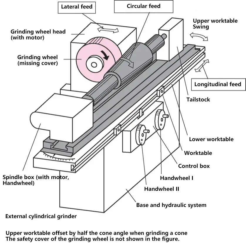
Grinding machines are high-precision machine tools. Workpieces processed by grinding machines should have high geometric accuracy, dimensional accuracy, and surface quality.
Common grinding machines mainly include surface grinders, universal tool grinders, cylindrical grinders, centerless grinders, etc.
IV. Milling
1. Basics of milling
(1) Overview
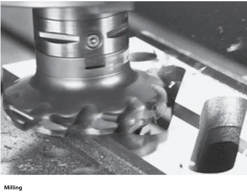
Milling is currently one of the most widely used metal cutting methods. It refers to the process of removing metal from the workpiece surface through the combined action of the rotating milling cutter and the feed motion of the workpiece relative to the cutter.
Characteristics of milling: It uses multi-edge milling cutters for cutting, offering high efficiency and a wide processing range, capable of machining various complex-shaped parts; it provides relatively high machining accuracy, reaching IT7 to IT9, with surface roughness values of Ra1.6 to 12.5μm.
(2) Milling operations
Cutting work involves the contact between the milling cutter and the workpiece, producing the machining process and machined surface.
Auxiliary work includes preparatory work before machining (installing tools and workpieces, adjusting machine parameters, etc.) and post-machining auxiliary work (stopping the machine, retracting the tool, removing the finished product, etc.).
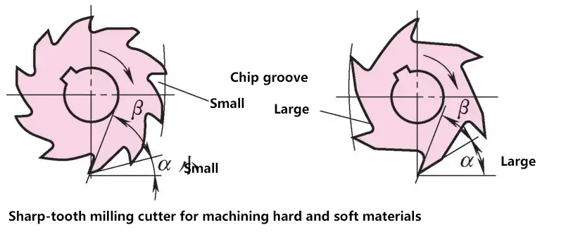
1) Cutting motion.
During the cutting process, the relative motion between the tool and the workpiece necessary to form the machined surface is divided into primary motion and feed motion. The primary motion is the motion that forms the cutting speed of the machine or consumes the main power, which is the rotation of the milling cutter. The feed motion is the motion that continuously feeds the workpiece material for cutting to form the cutting layer, which includes the movement and rotation of the workpiece, and the movement of the milling cutter, etc.
2) Auxiliary motion.
Motions necessary to complete auxiliary work during machining, such as the rapid approach of the milling table to the workpiece and its rapid return after cutting is completed.
3) Surfaces produced during cutting.
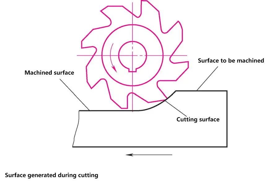
The surfaces produced during cutting are classified into three types: the surface to be machined, the machined surface, and the cutting surface.
(3) Milling parameters
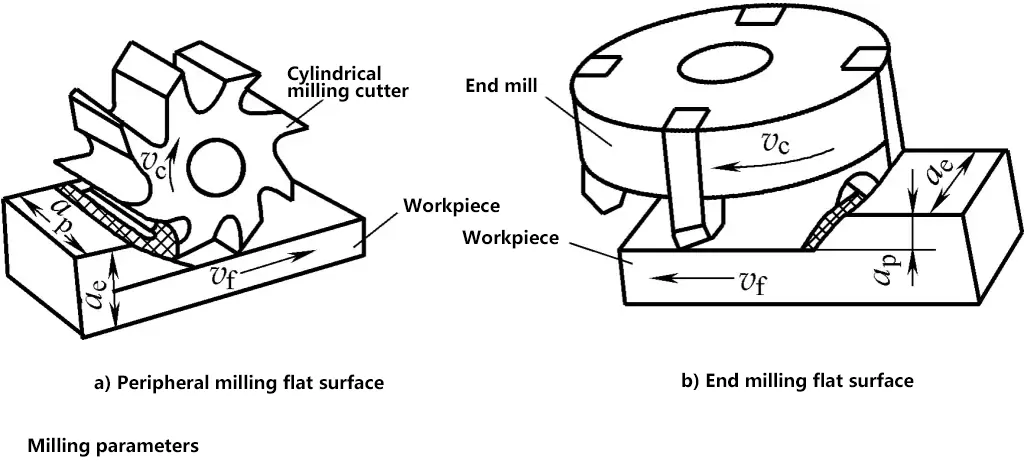
The process of the milling cutter removing chips during cutting motion involves many elements, with the basic parameters as follows.
1) Milling speed.
The distance traveled in 1 minute by the point farthest from the center on the milling cutter.
2) Feed rate.
In the milling process, the distance the workpiece moves relative to the milling cutter. Includes feed speed, feed per revolution, and feed per tooth.
3) Axial depth of cut.
(Corresponds to the milling depth for face milling cutters, opposite for cylindrical milling cutters) The depth of cut measured in the direction perpendicular to the workpiece plane and passing through the base point of the cutting edge, it is the depth of the tool entering the workpiece measured along the axis of the milling cutter.
4) Radial depth of cut.
(Corresponds to the milling width for face milling cutters, opposite for cylindrical milling cutters) The depth of cut measured in the direction parallel to the workpiece plane and perpendicular to the feed direction at the base point of the cutting edge, it is the dimension of the part of the workpiece being cut measured perpendicular to the axis of the milling cutter.
2. Classification of milling cutters
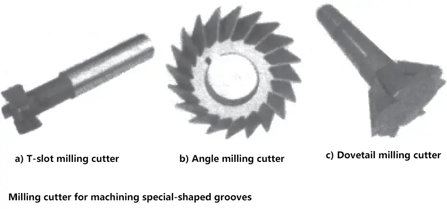
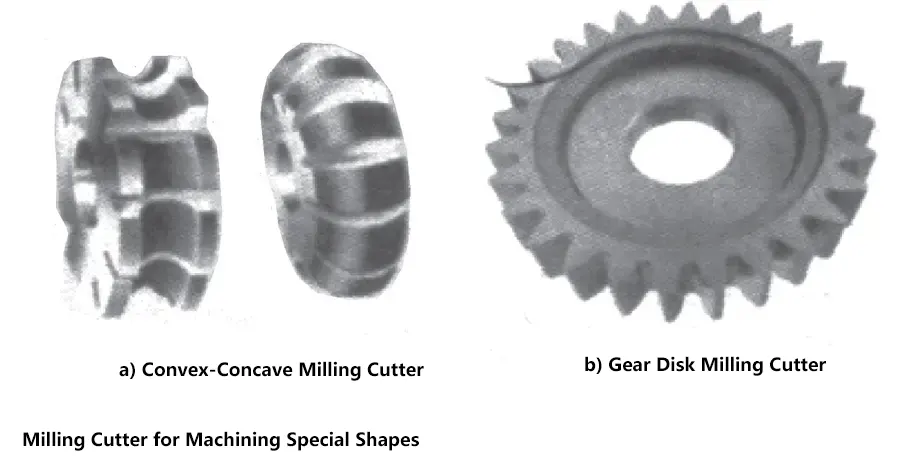
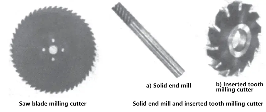
There are many types of milling cutters. By purpose, they can be divided into cutters for machining flat surfaces, right-angle grooves, special-shaped grooves, and special-shaped surfaces. By shape, they can be divided into solid and inserted tooth milling cutters.
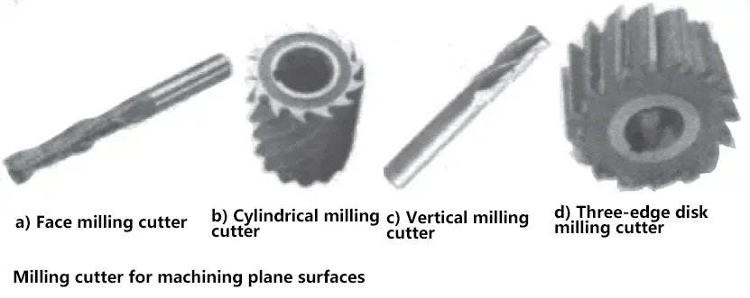

3. Basic methods of milling
Milling is an important method of metal material processing, which can be used for machining flat surfaces, inclined surfaces, special-shaped surfaces, grooves, and tooth shapes.
(1) Milling of flat surfaces
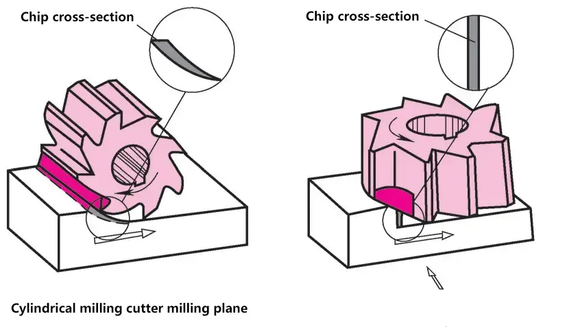
There are mainly two methods for milling flat surfaces on workpieces: peripheral milling and face milling.
Peripheral milling uses cutting edges distributed on the cylindrical surface of the milling cutter to form a flat surface. It includes up milling and down milling. Peripheral milling is mainly performed on horizontal milling machines, and the milled surface is parallel to the worktable surface.
The principles for choosing between up milling and down milling are: high machine precision and good rigidity, up milling is suitable for fine machining; up milling is used for fine machining of internal corners of parts; down milling for rough machining, up milling for fine machining.
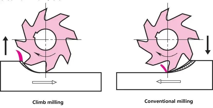
Face milling uses the cutting edges on the end face of the milling cutter to form a flat surface. Face milling can be performed on horizontal milling machines, and the milled surface is perpendicular to the worktable surface.
(2) Milling of inclined surfaces
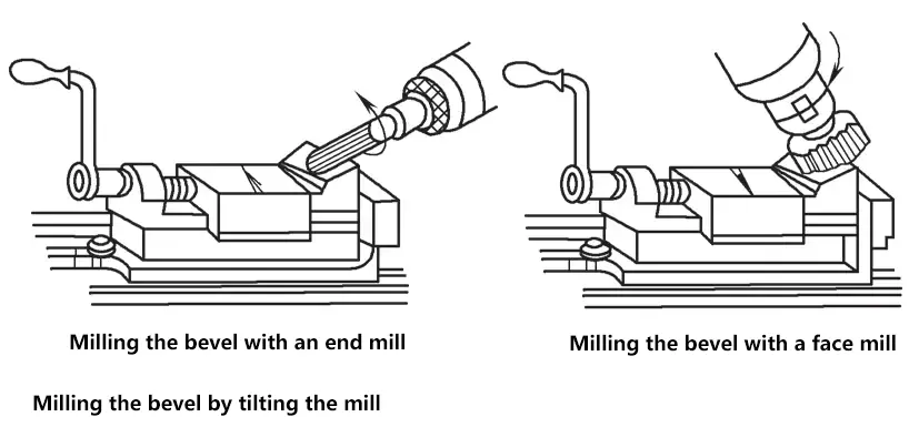
An inclined surface refers to a plane on the workpiece that is inclined to the reference plane, i.e., a plane that intersects with the reference plane at the required angle. There are three methods for milling inclined surfaces: tilting the workpiece, tilting the milling cutter, and using an angle milling cutter.
(3) Milling of grooves

There are many methods for machining grooves on milling machines, commonly used ones include right-angle grooves, V-shaped grooves, dovetail grooves, T-shaped grooves, and various keyways. In addition, splines, gears, and toothed clutches can also be machined by milling, but the requirements for milling cutters are relatively strict.
(4) Milling of special-shaped surfaces
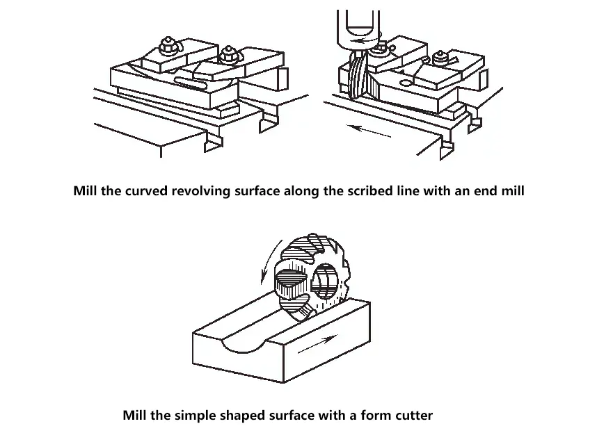
A surface whose shape is a non-circular curve in one or more cross-sectional directions is called a special-shaped surface. A special-shaped surface whose shape is a non-circular curve in only one cross-sectional direction is called a simple special-shaped surface. When the generatrix is short, it is called a curved rotational surface, such as the working profile of a cam. When the generatrix is long, it is called a formed surface.
V. Planing and Shaping
Planers and shapers are used for machining flat and curved surfaces.
1. Machining process and tools
(1) Planing
The main motion is completed by the worktable, while the tool performs the feed and depth of cut movements. The planing process is suitable for machining long and narrow surfaces. When conditions allow, multiple workpieces can be clamped on the worktable.
Compared to milling, the advantages of planing are less thermal deformation of the workpiece, higher machining accuracy, and lower tool cost; the disadvantages are longer processing time and higher power consumption for the main motion.
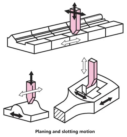
(2) Shaping
The main motion is completed by the tool, while the workpiece performs the feed movement. The shaping process is suitable for machining short surfaces and single-piece production. Horizontal shaping (bull-head shaper) is mostly used for machining shaped outer surfaces, while vertical shaping is mostly used for machining shaped inner surfaces.
(3) Feed rate f and axial depth of cut ap
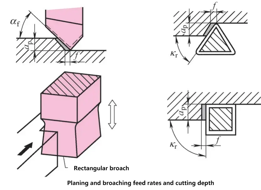
When transitioning from the return stroke to the working stroke, like in turning, the feed rate should be small and the axial depth of cut should be large in planing and shaping. The entering angle kr should be 45°. In vertical shaping, because the worktable movement is parallel or perpendicular to the cutting edge, the entering angle is 90°.
(4) Planing and shaping tools
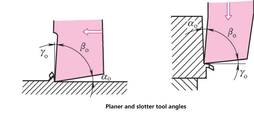
Like turning tools, they can be fitted with carbide inserts. Vertical shaping requires specialized tools.
(5) Tool lifting on return stroke
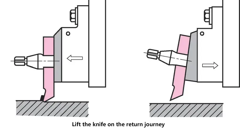
To prevent the cutting edge from rubbing against the workpiece during the return stroke, the tool must be lifted away from the workpiece when the worktable returns. The machine is equipped with an automatic tool lifting device.
Before starting work, check if the tool has accurately returned to the working position, otherwise there may be dangers such as tool breakage, workpiece scrap, and personal accidents.
(6) Cutting speed
The cutting speed depends on the materials of the workpiece and tool, and the size of the feed rate. In shaping, the cutting speed and number of strokes are estimated by the operator. When planing long workpieces, due to the long processing time, the cutting speed and number of reciprocating strokes must be accurately calculated.
Generally calculated using the formula
Number of reciprocating strokes = Cutting speed / (2 × Stroke length)
2. Planers and shapers
(1) Structure of a bull-head shaper
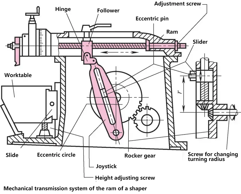
The ram of a bull-head shaper uses mechanical transmission (crank-rocker mechanism) or hydraulic transmission.
A bull-head shaper mainly consists of a bed, ram, worktable cross rail, worktable, main motion gearbox, and feed mechanism.
(2) Structure of a shaper
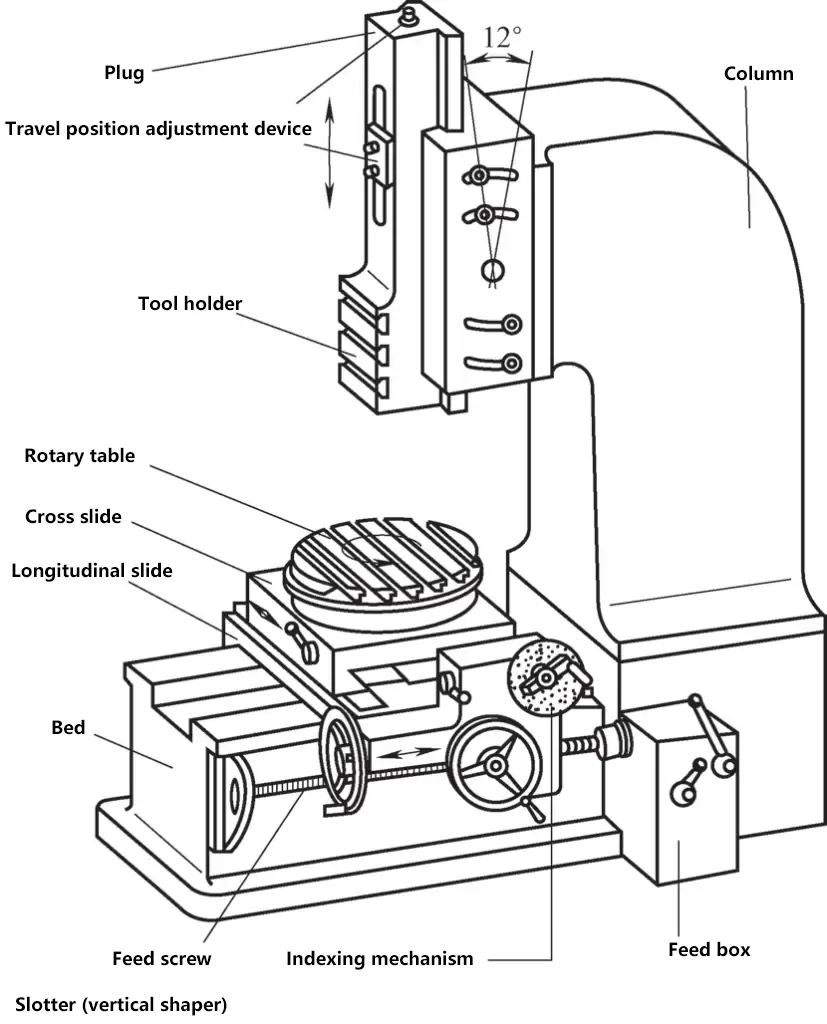
The main motion of a shaper is vertical linear motion, performed by the tool.
Shapers are suitable for machining internal flat surfaces or internal curved surfaces in single-piece production. A shaper mainly consists of a column, bed, ram, worktable, ram drive system, and feed mechanism.
VI. Broaching
Broaching is a cutting process that uses a long bar-shaped tool (broach) to cut through a hole in the workpiece or along the outer surface of the workpiece. According to the characteristics of the machined surface, broaching is divided into internal broaching and external broaching.
1. Broach, chip formation, and cutting parameters
Since processing a specific shape of workpiece requires a corresponding shape of broach, broaching is only suitable for mass production.
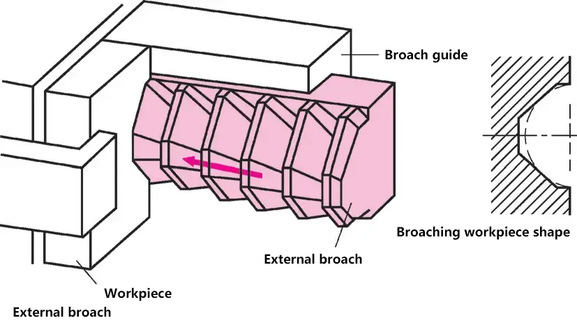
(1) Parts of the tool
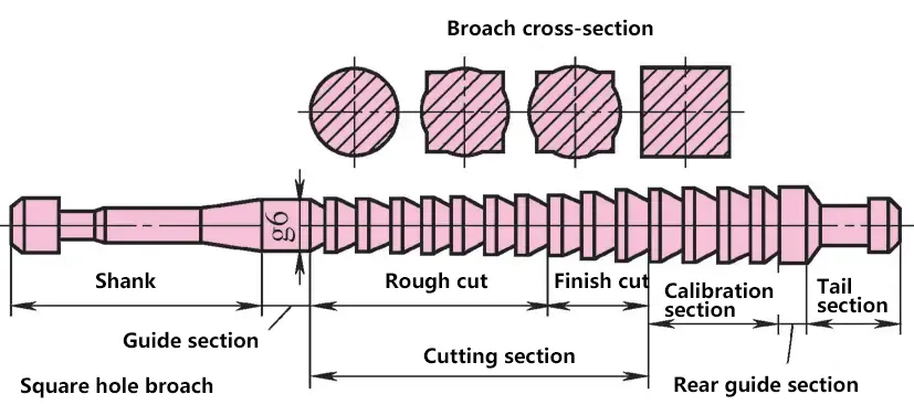
- Shank – used to clamp the broach and transmit power.
- Front pilot section – serves as a guide to prevent the broach from skewing.
- Cutting section – performs the cutting work, composed of roughing teeth and finishing teeth.
- Burnishing section – serves to polish and calibrate, and acts as backup teeth for the finishing teeth.
- The structure of the broach and the shape of the teeth are related to the broaching method.
(2) Chip formation
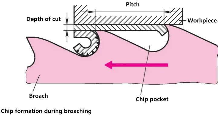
The broach only performs longitudinal movement (main motion). Since the dimensions of the teeth gradually increase from front to back, there is no need for feed even to achieve continuous cutting. The rise per tooth (equal to the axial depth of cut) depends on the material. When resharpening a dull broach, the original tooth rise must be strictly maintained. To provide enough space for curled chips in the chip pockets, they must be ground out.
(3) Points to note
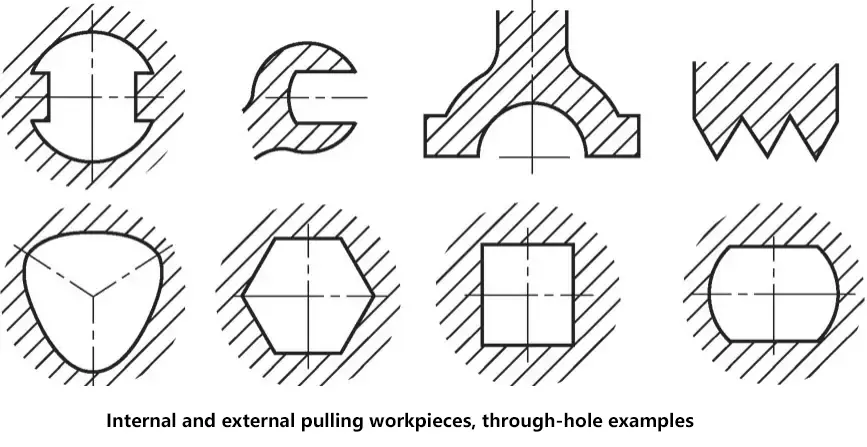
To maximize the efficiency of broaching, the following points must be noted:
1) Correct tooth rise.
If the tooth rise is too large, the tool will be overloaded, leading to chipping. If the tooth rise is too small, the broach needs to be greatly lengthened, or machining needs to be done in several passes, or several broaches need to be used.
2) Correct selection of cutting speed.
Excessive cutting speed will shorten the life of the broach, while too low cutting speed will extend the machining time.
3) Appropriate lubrication and cooling.
Appropriate lubrication and cooling can extend the life of the broach and reduce surface roughness.
4) Timely tool sharpening.
Timely tool sharpening is a prerequisite for reducing surface roughness and broaching force. It is necessary to understand the dulling condition of the broach. The characteristics of a dull broach are: rounded cutting edges; high broaching force; oversized machined workpieces with rough surfaces.
2. Broaching machines
Broaching methods are usually divided into two categories: layer broaching and section broaching.
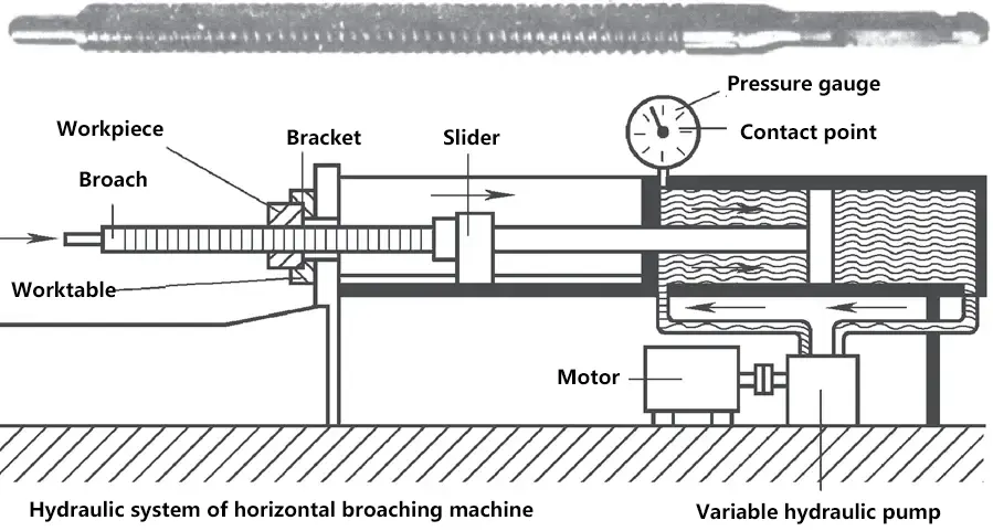
Large production batches are necessary to ensure the economic efficiency of broaching. Broaching machines are suitable for mass production.
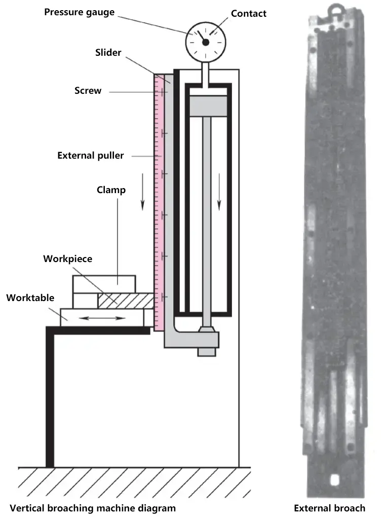
When necessary and possible, broaching machines can be equipped with automatic loading or integrated into automatic lines. Broaching machines generally use hydraulic transmission. The characteristics of broaching machines are as follows:
- The broaching motion is uniform, without impact or vibration.
- The broaching speed can be infinitely adjusted.
- The broaching force can be controlled and adjusted through a pressure gauge.

