Hole Machining: Equipment, Tools, and Operations
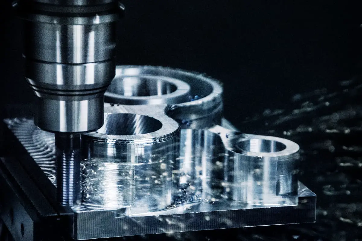
How do machines get those perfect holes? From tiny gadgets to huge factory tools, precise holes are key. This article…
Imagine trying to carve a sculpture from a diamond. Machining difficult materials, like titanium and Inconel, presents similar challenges in the manufacturing world. This article delves into the intricacies of cutting through these stubborn substances, revealing the tools and techniques that make it possible. Learn how modern technology and skilled craftsmanship come together to shape the seemingly unshapeable, and uncover insights that could revolutionize your approach to machining tough materials.
Compared to general metal materials, difficult-to-machine metal materials have significant differences in chemical composition, metallographic structure, physical and mechanical properties, and poor machinability. Therefore, during the cutting process, it is necessary to flexibly apply cutting principle knowledge according to the characteristics of the processed material, and specifically select lathe tool materials and tool geometric angles.
Due to the many types of these materials, only a few of the more common difficult-to-machine metal materials will be introduced here.
Due to the addition of many alloying elements in metal materials, their physical and chemical properties have been adapted to meet usage requirements, but this has brought great difficulties to metal cutting.
This section briefly introduces the cutting performance, tool material selection, tool angle selection, and cutting parameter determination for several common and representative special, difficult-to-machine metal materials and non-metallic materials in production.
The higher the strength or hardness of the workpiece material, the greater the cutting force and the higher the cutting temperature, which will accelerate tool wear.
Additionally, when cutting high-hardness materials, the contact length between the cutting edge and the chip is shorter, and the cutting force and heat are concentrated near the cutting edge, easily causing the cutting edge to peel off or even chip. This is more evident for brittle tool materials like cemented carbide. Therefore, the machinability of such materials is poor.
The greater the plasticity of the workpiece material, the larger the chip deformation, the more cutting heat generated, and the easier for chips to adhere to the tool, thus accelerating tool wear.
However, if the plasticity of the workpiece material is too low, the contact length between the cutting edge and the chip will be very short, which will also cause severe tool wear. Therefore, whether the plasticity of the workpiece material is too high or too low, the machinability is poor.
The better the heat resistance of the workpiece material, the more it can maintain high strength and hardness at high temperatures, making cutting more difficult.
The stronger the abrasive ability of the workpiece material, the greater the wear on the tool, and the poorer the machinability.
The lower the thermal conductivity of the workpiece material, the less easily the cutting heat dissipates, the higher the cutting temperature, the more severe the tool wear, and the poorer the machinability.
Stainless steel can be classified into chromium stainless steel (such as Cr13, 4Cr14, etc.) and chromium-nickel stainless steel (such as 1Cr18Ni9Ti) according to its chemical composition. The turning characteristics of stainless steel are as follows:
1) Stainless steel has high strength and hardness at high temperatures. For example, austenitic stainless steel maintains its mechanical properties even at temperatures up to 700°C, making cutting difficult and resulting in high cutting resistance.
2) High plasticity and good toughness result in large cutting deformation and correspondingly high cutting forces and heat.
3) Poor thermal conductivity, with a thermal conductivity 1/4 to 1/2 that of medium carbon steel, resulting in higher cutting temperatures on the turning tool, accelerating tool wear.
4) Strong adhesion tendency. During the cutting process, chips easily adhere to the tool, forming built-up edges, making it difficult to obtain a good surface quality, and easily causing wear on the cutting edge.
5) The machined surface of stainless steel is prone to work hardening, exacerbating tool wear.
6) High toughness makes chips difficult to break and curl. During the cutting process, chips can easily clog, affecting surface quality and damaging the cutting edge.
The cutting part of the tool should be made of materials with high hardness, good toughness and heat resistance, and low adhesion to stainless steel.
When using high-speed steel, cobalt-containing high-speed steel and super-hard molybdenum-containing high-speed steel should be selected, such as W2Mo9Cr4VCo8, etc. When using cemented carbide, YG types should be chosen, such as YG8, YG6, YG8N, and YG6X, etc. Generally, YT types are not used, or YW1 and YW2 with added niobium carbide are used.
The geometric parameters of the turning tool are selected as follows:
1) The rake angle is generally chosen as γ₀ = 12° to 30°. When machining martensitic stainless steel (such as 2Cr13), a larger rake angle can be used; when machining austenitic + ferritic stainless steel, a smaller rake angle is used; when machining stainless steel with lower hardness, a larger rake angle can be used.
2) The clearance angle is generally taken as α₀ = 6° to 12°, with a larger clearance angle preferred when the cutting thickness is small.
3) The entering angle is generally chosen as K₀ = 60° to 75°.
4) The end cutting edge angle should be chosen as small as possible, k’₀ = 8° to 15° for rough turning of external cylinders; it can be chosen larger for fine turning of external cylinders, but ensuring that the tool tip angle is not less than 90°.
5) The inclination angle is generally taken as a negative value, i.e., λ₀ = -8° to -3°. For interrupted cutting, a larger absolute negative value is taken, i.e., λ₁ = -10° to -5°.
6) The tool nose radius r₀ = 0.5 to 1mm. To facilitate chip evacuation and curling, an arc-shaped chip breaker groove is often used.
Example 1
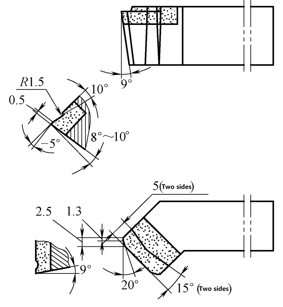
Figure 1 shows a 90° external cylindrical turning tool for stainless steel, with the following tool characteristics:
1) Insert material: YG8 cemented carbide.
2) Tool characteristics: The main feature of the tool is composed of a large rake angle and an arc-shaped chip breaker groove. The chip breaker groove has a 15° inclination angle, forming a wider front and narrower back shape, causing the chip to flip towards the surface to be machined and break when it hits the back of the tool or the transition surface of the workpiece.
3) Cutting parameters: Cutting is smooth within the range of v₀ = 120-150m/min, f = 0.2-0.4mm/r, a₁ = 1-2mm, with good chip breaking effect.
4) Application range: Suitable for turning 1Cr18Ni9Ti stainless steel shaft-type workpieces with poor rigidity.
Example 2
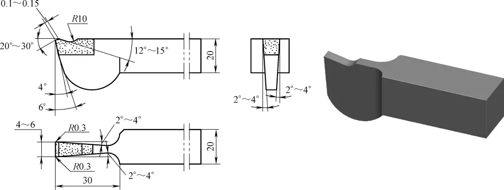
Figure 2 shows a 45° external cylindrical turning tool for stainless steel, with the following tool characteristics:
1) Insert material: YW1 cemented carbide.
2) Tool characteristics: The tool has an extremely narrow (b₀ = 0.1mm) and highly inclined (γ₁ = -10°) negative chamfer, as well as a chip breaker groove composed of a rake angle γ₂ = 12° to 15° and an R = 10mm arc, to increase strength, achieve smooth chip breaking, overcome the “sticking” phenomenon, and achieve high tool life.
The tool nose radius is relatively large, providing good heat dissipation. The machined surface roughness Ra value can reach 3.2 to 1.6μm.
3) Cutting parameters: vc = 120-180m/min; f = 0.4-1mm/r; ap = 4-7mm.
4) Application range: Suitable for semi-finish turning of chromium-nickel system stainless steel on CA6140 horizontal lathe.
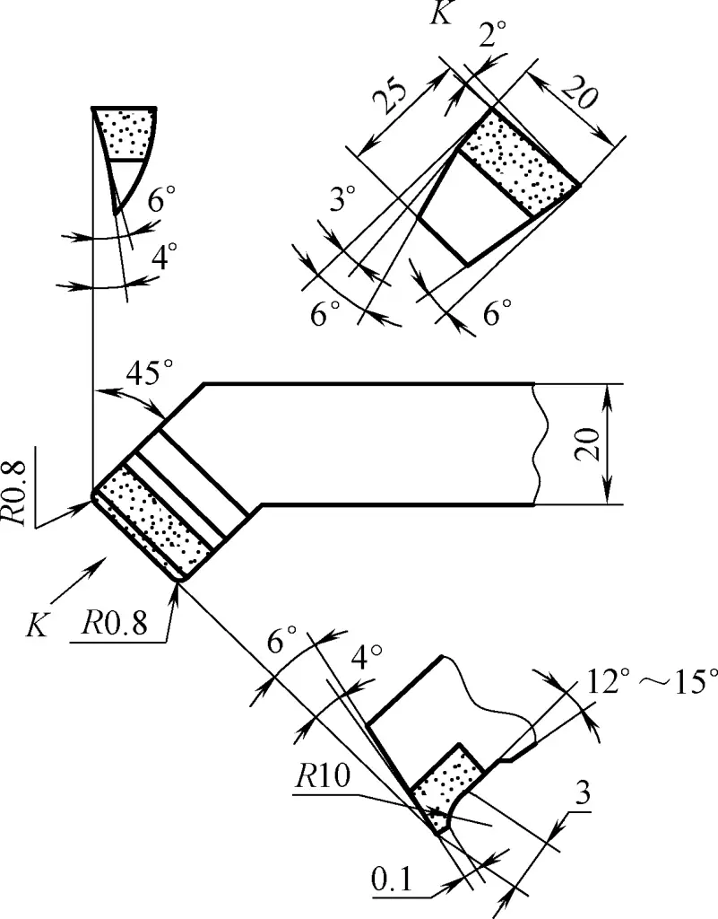
Example 3
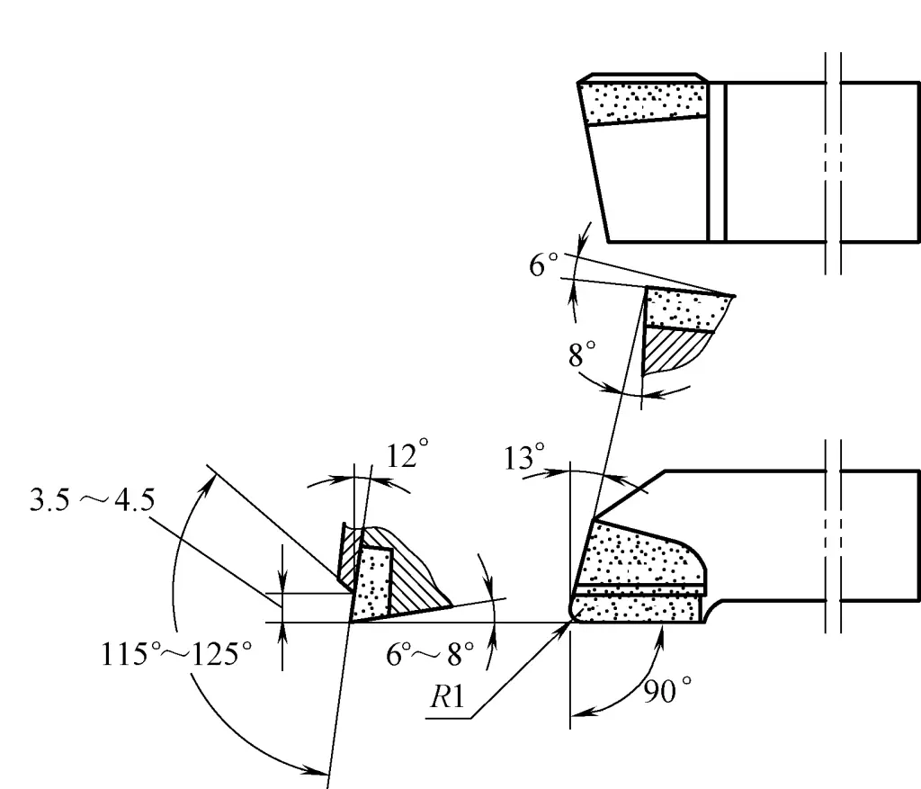
Figure 3 shows a stainless steel parting tool, with the following tool characteristics:
1) Insert material: YW1 cemented carbide.
2) Tool characteristics: It has an extremely narrow (b₀ = 0.1-0.15mm) and highly inclined (γ₁ = -30° to -20°) chamfer; as well as a chip breaker groove formed by a 12° to 15° rake angle and an R = 10mm arc, reducing cutting force and allowing for increased feed rates during parting operations.
It also overcomes the defect of tool tip chipping caused by stainless steel chip adhesion, allowing for smooth chip evacuation.
3) Cutting parameters: vc = 120-200m/min; f = 0.2-0.5mm/r.
4) Application range: For parting stainless steel workpieces such as 1Cr18Ni9Ti on CA6140 or CA630 horizontal lathes.
During the turning process, we sometimes encounter steel with a hardness of 40-60 HRC after quenching. The turning characteristics of such quenched hardened steel are:
1) Quenched hardened steel has high hardness and large unit cutting resistance. For example, when 45 steel has a hardness of 44 HRC, its unit cutting resistance is 35% higher than in the normalized state.
2) Quenched hardened steel has low thermal conductivity. Due to high cutting resistance, the cutting temperature is high. For example, the cutting temperature of 45 steel with a hardness of 44 HRC is about 45% higher than in the normalized state, which accelerates tool wear and easily causes damage.
3) After quenching, the plasticity of hardened steel decreases, resulting in less plastic deformation during cutting, making it less likely to form built-up edges, which can reduce the roughness of the machined surface.
The cutting part of the turning tool should be made of cemented carbide tool materials with good heat resistance, wear resistance, and high hardness. For rough turning, choose YT5, YW2; for semi-finish and finish turning, choose YT30, YN10, YH1, and YH2.
The geometric parameters of the turning tool are selected as follows:
1) The rake angle is generally chosen as γ₀ = 0° to -10°. The higher the hardness, the larger the absolute value of the negative rake angle should be. When γ₁ = 0° is chosen, a 2-3mm wide negative chamfer needs to be ground.
2) The clearance angle is chosen as α₀ = 6° to 10°.
3) The entering angle is generally taken as K₀ = 30° to 60°. If the rigidity of the technological system is good, a smaller entering angle can be chosen.
4) The end cutting edge angle is generally taken as K’₀ = 6° to 15°, with larger values for semi-finish turning and smaller values for finish turning.
5) The rake angle λs is taken as -5° to 0°, with a larger negative value for semi-finishing and λs = 0° for finishing. Under impact conditions, take λs = -20° to -10°.
6) The nose radius is taken as rε = 1 to 2mm.
Example 1
Figure 4 shows a turning tool for hardened steel, with the following characteristics:
1) Tool insert material: YW1, YW2, or YT30 carbide.
2) Tool characteristics: The tool has a large nose angle and nose radius, thus providing better strength and heat dissipation for the cutting part. The tool uses a negative rake angle γ o = -15° to -10°, which strengthens the cutting edge.
3) Cutting parameters: vc = 75-80m/min; f = 0.3-0.4mm/r; ap = 0.8-1.2mm.
4) Application range: Suitable for turning hardened steel workpieces with hardness of 40-58HRC on C616, C6140, or C630 horizontal lathes.
Example 2
Figure 5 shows a curved finishing tool for hardened steel, with the following characteristics:
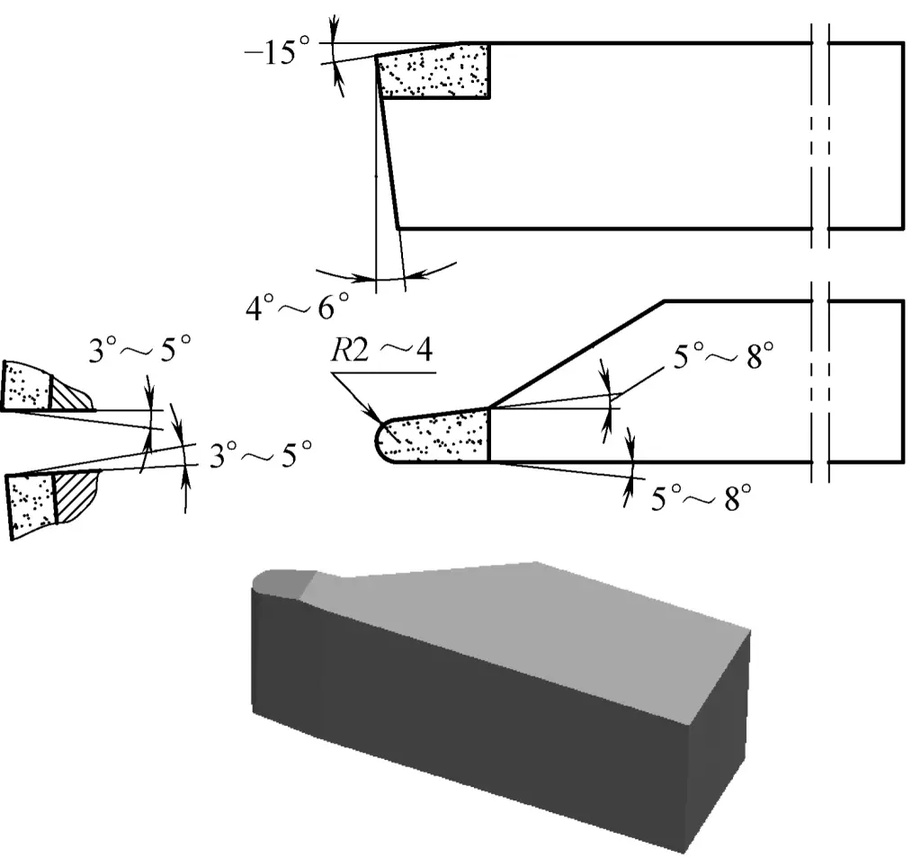
1) Tool insert material: YG3 or YW1 carbide.
2) Tool characteristics: Rake angle γo = -15°, strengthening the cutting edge. The rounded tool tip helps reduce residual height, decrease workpiece surface roughness, and increase tip strength.
The size of the nose radius can be ground according to workpiece requirements. The front and back faces should be ground, with a surface roughness Ra value of 0.4μm.
3) Cutting parameters: vc = 130-160m/min; f = 0.2-0.3mm/r; ap = 0.02-0.3mm.
4) Application range: For finishing of hardened medium carbon steel with hardness 45-55HRC, roller convex and concave arc profiles, end face grooves, etc.
Chilled cast iron is used to manufacture large workpieces such as rolling mills and wheels.
Chilled cast iron is a wear-resistant cast iron with high hardness and high compressive strength, with wear resistance under high pressure. When grinding turning tools for chilled cast iron, the following turning characteristics should be understood.
1) High surface hardness, with a chilled layer depth of 8-40mm, and high thermal strength. It has very low plasticity, short tool-chip contact length, high cutting resistance, and high cutting temperature concentrated near the cutting edge, making the cutting edge prone to chipping.
2) Chilled cast iron parts generally have large structural dimensions and large total machining allowance, which further increases the difficulty of processing.
3) The surface layer of chilled cast iron is white cast iron, which is hard and brittle. During cutting, it can easily produce chipping, causing rejects.
4) Chilled cast iron workpieces are formed by casting, with uneven surface allowance and defects such as blowholes and sand inclusions. During rough turning, there is significant impact, which can easily damage the tool.
The cutting part material of the tool is generally selected from YG (such as YG6, YG8), YW, and YH class carbides. In addition, composite alumina or silicon nitride ceramics are also very effective for finishing and semi-finishing of chilled cast iron.
The selection of turning tool geometric parameters is as follows:
1) Choose a smaller rake angle, generally taking a negative value, γo = about -2°. The higher the hardness, the larger the absolute value of the negative rake angle should be.
2) The relief angle should not be too large, αo = 4°-8°.
3) The selection principles for the lead angle, end cutting edge angle, inclination angle, and nose radius can refer to those for hardened steel turning tools.
Example
Figure 6 shows a turning tool for chilled cast iron rolls, with the following tool characteristics:
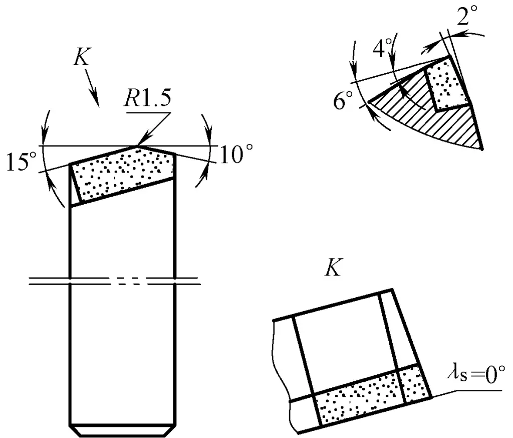
1) Tool insert material: YG6 carbide.
2) Tool characteristics: Due to the high hardness of the roll surface layer, a smaller rake angle γo = -2° is chosen. The lead angle is taken as Kr = 15°, which is relatively small, aiming to improve the tool head’s heat dissipation condition, increase the tool life, and also make the tool entry and exit more stable, reducing the possibility of roll edge chipping and tool breakage.
A nose radius of rε = 1-1.5mm is ground, and an inclination angle of λs = 0° is taken, giving the tool tip very high strength and heat dissipation capacity, and improving cutting stability.
3) Cutting parameters: vc =4~7m/min; f=0.5~0.8mm/r; ap =3~6mm.
4) Application range: Suitable for turning the outer diameter of chilled cast iron rolls on roll lathes.
Example
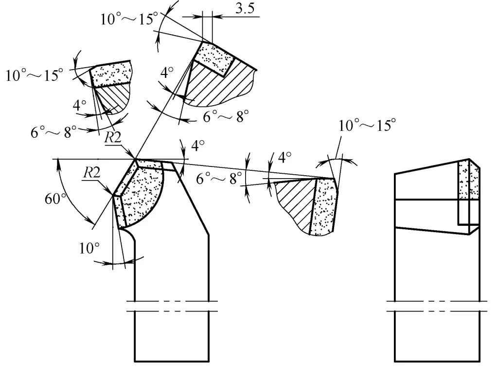
The turning tool for heat-resistant alloy steel is shown in Figure 7, with the following tool characteristics:
1) Tool material: YT15, YG8 carbide.
2) Tool features: Has double transition edge and finishing edge; ground with br1 =0.5mm, γo1 =-5°. Negative chamfer and front angle γo =10° arc chip breaker groove, good tip strength, good chip breaking, suitable for large feed and heavy-duty cutting of outer diameter and end face.
3) Cutting parameters: vc =50~100m/min; f=0.5~1mm/r; ap =1.5~3mm.
4) Application range: Turning of outer diameter and end face of chrome-nickel steel, chrome-nickel-molybdenum steel, and heat-resistant alloy steel.
The high-speed steel turning tool is shown in Figure 8, with the following features:
1) The tool insert is YG8 carbide; the chip breaker is W9Cr4V2 high-speed steel; the tool shank is 45 steel and has undergone quenching and tempering treatment.
2) Tool features: Has a positive rake angle of γo =12°, and a separate high-speed steel chip breaker is welded on, inclination angle λs =-6°, good chip breaking effect during turning.
3) Cutting parameters.
4) Application range: Turning of outer diameter of high-speed steel and heat-resistant alloy steel.
vc =150~500m/min; ap and f are the same as for ordinary steel. However, when chip evacuation is not smooth, the feed rate f should be appropriately reduced.
Emulsion can be used for cooling and lubrication during rough turning, but using emulsion during finish turning may cause corrosion on the workpiece, so kerosene or compressed air cooling can be used.
In addition to the common characteristics of non-metallic materials such as poor thermal conductivity and low strength, rubber materials also have extremely high elasticity. Therefore, during turning, the material has high elasticity and flexibility, wear resistance, and good chemical corrosion resistance and insulation properties.
This is especially true for soft rubber workpieces. Therefore, rubber products are widely used in industry. The vast majority of rubber products are formed by hot pressing in molds, but a small number of components need to be shaped by cutting.
Commonly selected tool materials include: T8A, T10A, T12A carbon tool steel and W18Cr4V high-speed steel. When turning hard rubber with more impurities, due to the poor wear resistance of high-speed steel and other tool materials, carbide tool materials can also be used depending on specific circumstances.
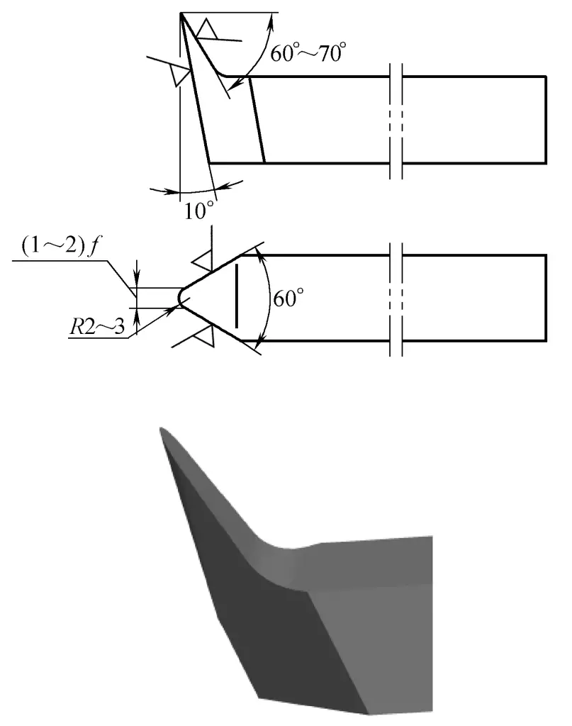
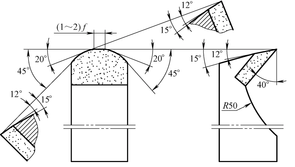
The main feature of the tool is to ensure smooth turning and make the turning tool as sharp as possible, using a large rake angle of γo =65°~75° and a relatively large relief angle. Otherwise, it is difficult to achieve the required accuracy and good surface quality during turning.
To reduce friction between the back of the turning tool and the workpiece surface, disperse cutting forces and heat, the turning tool is ground with an R2~3mm circular transition edge and a finishing edge with b’ε =(1~2)f, K’ ε =0°.
To ensure smooth chip evacuation, the front of the turning tool is ground into a chip groove composed of a large rake angle plane and an arc shape. The angle selection for commonly used rubber outer diameter turning tools: rake angle is 60°~75°, relief angle is about 10°, wedge angle is 10°~15°, as shown in Figures 9 and 10.
Due to the low strength and good elasticity of rubber, elastic deformation is likely to occur during turning, so special attention should be paid to the workpiece clamping method. For example: a flat wooden board can be mounted on the chuck to nail down rubber sheets, or a wooden core shaft can be used to clamp sleeves and ring-shaped workpieces to enhance the rubber’s ability to resist cutting.
The cutting performance of hard and soft rubber varies greatly, and should be selected based on the cutting form, turning tool angle, and different types of rubber. Generally, a higher cutting speed is chosen. The cutting parameters are generally: vc =100~150m/min, f=0.5~0.75mm/r, ap =2~6mm.
Oil should not be used as cutting fluid during turning to prevent oil from corroding the rubber and causing deformation. If specially needed, water cooling can be used.
However, because this type of material has low thermal conductivity and heat is not easily dissipated, tungsten-cobalt carbides with good thermal conductivity should be selected: YG8, YG6.
Tool geometry parameters: For rough turning, rake angle γo =40°~45°, relief angle αo =8°~12°; for finish turning, rake angle γo =45°~55°, relief angle αo =10°~15°, generally a cutting wedge angle βo =20°~30° is appropriate.
The part connecting the tool shank and the front face is ground into a large arc to allow smooth chip evacuation. Figure 11 shows a carbide outer diameter turning tool for rubber, used for turning the outer diameter of large rubber parts.
The most prominent features when turning acrylic are: high cutting temperature causes deformation, and even local melting into nodules; at lower temperatures and excessive cutting forces, brittle fracture may occur; additionally, achieving a certain degree of surface brightness is quite challenging.
(2) Selection of tool materials and geometric angles Commonly used materials include YG6, YG8, and W18Cr4V. Acrylic turning tools use a rake angle of 30°~40°, relief angle of 10°~12°, inclination angle of 5°~20°, and other geometric angles similar to general turning tools.
Feed rate is 0.08~0.3mm/r; Cutting speed: For rough turning, the cutting speed is slightly higher than that of general steel; for finish turning and turning thin-walled workpieces, the cutting speed should be slightly lower than when turning steel parts to reduce deformation caused by cutting heat. The depth of cut can be selected with reference to general steel parts.
Turning can be divided into: finish turning, leaving allowance for grinding; semi-finish grinding, using F400 water sandpaper with water to remove tool marks; finish grinding, using F600 water sandpaper with water for grinding; polishing, using clean cotton or soft cloth with machine oil and polishing paste for polishing.
Practice has shown that using toothpaste for polishing also yields very good results. Wash and air dry after polishing.
When turning acrylic materials, pay attention to the following points:
1) The cutting edge should be sharp to prevent workpiece deformation and poor surface quality. Use a positive inclination angle to prevent chips from pulling on the machined surface.
2) The depth of cut and feed rate should not be too large to prevent workpiece fracture and deformation.
3) Prevent excessive temperature causing deformation and excessive cutting force causing brittle fracture. To achieve this, compressed air or a small amount of cutting fluid can be used for cooling during machining to control the cutting temperature.
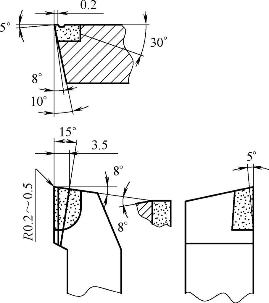
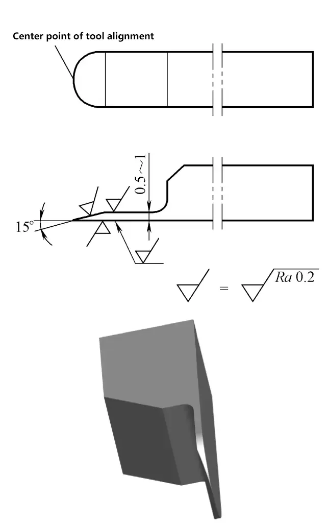
Figure 12 shows a non-metallic outer diameter finish turning tool with the following features:
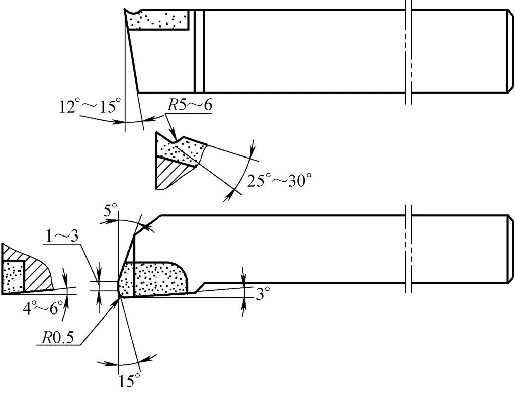
1) The tool insert material is YG8, YG6 carbide.
2) The turning tool features a larger rake angle, ground with an arc chip breaker groove, and ground with an inclination angle λs =5°, making cutting light and smooth, with smooth chip evacuation, and a 1~3mm finishing edge for smaller surface roughness.
3) Cutting parameters: vc =150~180m/min, f=0.3~0.5mm/r, ap =0.1~0.5mm.
4) The turning tool is suitable for turning cloth-reinforced bakelite, hardwood, acrylic, and fiberglass and other non-metallic materials.