During the processing of sheet metal components, various deformations may occur, such as springback deformation after the removal of external forces, stress deformation caused by internal stresses due to material constraint, deformation due to heat treatment, deformation from material transportation or collisions, and deformation caused by irregular raw materials, among others. If these deformations in the parts are not corrected, they can affect the proper assembly of the entire sheet metal structure, reduce assembly quality, and even jeopardize the strength and service life of the component.
The process of eliminating deformations in sheet metal components is collectively known as straightening. Straightening is a method used to correct the geometric shape of steel structures and raw materials that do not meet product requirements, by causing a certain degree of plastic deformation, thereby achieving the geometry required by the product. All deformations must be straightened before subsequent processing or assembly can proceed. Straightening is one of the important basic operations in sheet metal processing.
Common methods of straightening sheet metal include manual straightening, mechanical straightening, and flame straightening. Manual straightening is primarily used to correct the shape and size defects of sheet metal parts after forming, or for situations where mechanical straightening is not possible due to limitations in production equipment. Because manual operation is flexible, effective, and low-cost, it is widely used in production.
Mechanical straightening is generally used for straightening and flattening metal raw materials and large sheet metal blanks (sheet metal, section steel, etc.). Flame straightening is mainly used for straightening and flattening large sheet metal components. Since it is minimally affected by processing sites and equipment conditions, it is especially suitable for operations in the field or in non-workshop settings.
Manual straightening uses hand tools (sledgehammers or hammers) to strike specific parts of a workpiece on a work platform. Through the “compression” and “relief” operations on the blank, the metal in the tighter areas is stretched, causing the fiber lengths of all layers to tend toward uniformity, thereby achieving straightening. Since sheet metal components differ in material, structure, and causes of deformation, the specific methods of manual straightening also vary.
I. Manual Straightening Techniques for Thin Steel Plates
Thin steel plates are particularly prone to deformation during transportation and product manufacturing due to localized stress, high temperatures, or being stored unevenly outdoors for extended periods. Correcting thin steel plates is a highly skilled and relatively challenging operation.
During the straightening process, you must first analyze the type of deformation or the combination of basic deformations present, based on the condition of the thin plate. After determining which areas of the plate are loose (long fibers) and which areas are tight (short fibers), proceed with the subsequent straightening operations.
1. Determining “Loose” and “Tight”
“Loose” and “Tight” are the terms used by sheet metal workers to describe the uneven surface conditions of steel plates due to differences in localized stress. In practice, areas where the material is stretched and appears uneven or buckled are referred to as “loose,” while areas where the material hasn’t deformed and remains flat are called “tight.” The objective of straightening is to loosen the “tight” areas or tighten the “loose” areas, achieving uniform tension throughout the plate to correct the deformation.
Before straightening, you should inspect the deformation of the steel plate. “Loose” or “Tight” areas can be identified based on experience: areas that appear raised or depressed, moving noticeably when pressure is applied, are classified as “loose,” while relatively flat areas are considered “tight.” When an uneven thin steel plate is placed on a solid flat platform, some areas will lift, while others will press firmly against the platform.
If the edges of the thin plate lie flat against the platform but the center bulges, the center is “loose” and the edges are “tight.” If the center lies flat but the edges form a wavy shape, then the edges are considered “loose.”
If the distinction between “Loose” and “Tight” in a steel plate is unclear, you can start by applying circular hammering to appropriate internal regions near the edges, transforming the irregular deformations into regular patterns. Afterward, proceed to relax the tight areas.
In cases where there is severe local bulging that makes it difficult to relax the surrounding areas, apply localized heating to the bulging area first. This causes the bulging area to shrink until it is mostly flat, after which cold straightening can be applied. When correcting, ensure that the workpiece is flipped and struck on both sides.
2. Thin Steel Plate Straightening Operations
Deformation patterns in thin plates include bulging in the center, wavy edges, and upward warping at the corners, as shown in Figure 1.
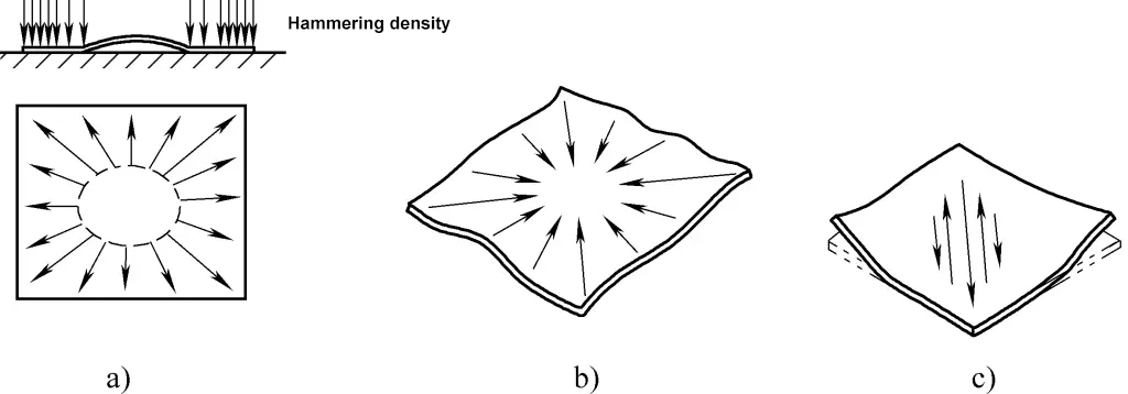
a) Bulging in the Center
b) Wavy Edges
c) Upward Warping at the Corners
Figure 1 shows the straightening of a bulge in the center of a thin steel plate. A bulge in the center indicates that the fibers in the middle of the plate are longer than around the edges, which is commonly described as the edges being “tight” and the center “loose.”
The bulging area resembles a wet spot on a thin piece of paper that has some absorbency; when viewed from one side, the bulging part is higher than the surrounding flat plane, and its edges are in a taut state. From the opposite side, the area appears lower than the surrounding surface, with the edges also in a taut condition. If the lengths of the plate’s fibers are corrected to be relatively the same, the bulge will disappear, and the plate will become flat.
In manual straightening, one should hammer around the edges of the plate, starting near the bulging area and gradually extending outward, as shown by the arrows in Figure 1. The closer to the edges you get, the denser and harder the hammering should be. The goal is to stretch the circumferential fibers around the bulging area proportionally in the radial direction. This equalizes the lengths of the fibers across the plate, thus eliminating the central bulge.
If there are several adjacent bulging spots on the surface of the thin plate, you should first lightly hammer the areas between the bulges to merge several spots into one area. Then, apply the aforementioned method to hammer around the edges and flatten the plate.
Figure 1b shows the straightening of wavy edges on a plate. This deformation indicates that the fibers around the edges of the plate are longer than those in the center. In other words, the edges are “loose” and the center is “tight,” much like a soaked sheet of paper that has dried.
Manual straightening of wavy edges should involve hammering gradually from the edges toward the center, as shown by the arrows in Figure 1b. The density of hammer strokes should increase from the edges to the center, and the force of each strike should also increase, so that the fibers in the center stretch. Eventually, the fiber lengths across the entire plate will equalize, achieving the desired straightening result.
If the thin plate experiences irregular deformations such as twisting, like the diagonal warping deformation shown in Figure 1c, it indicates that there is a tensile stress area perpendicular to the direction of the diagonal warp in the middle area of the thin plate, and the tensile stress direction is along the long direction of this stress area.
From this analysis, the deformation of the thin plate is caused by the fibers in the direction of tensile stress being slightly shorter than those around them. During manual correction, one should start hammering progressively towards the center from both ends along the direction of the stress area, causing the fibers in the stress area to stretch and become as long as the surrounding fibers, thus achieving correction.
For the three types of deformations mentioned above, correction can also generally be done using a striking board (also known as a slapper). The striking board is made from a steel plate with good elasticity, with a thickness of 3-5 mm, a width of no less than 40 mm, and a length of no less than 400 mm. The specific dimensions of the striking board depend on the thickness and size of the plate being corrected.
The purpose of striking the raised (or loosened) part of the deformation area with the striking board is to cause the fibers in the material being struck to shorten, aligning them with the surrounding fibers in length, thereby achieving correction.
Since the thickness of the striking board is much greater than that of the thin plate, and its stiffness is also higher, it can also compress and stretch the fibers in the tensioned areas of the material to achieve correction. Because the contact surface between the striking board and the corrected plate is large and the force is evenly distributed, there are no hammer marks, and the correction efficiency is relatively high. However, the deformation caused by striking is not very large, so it is only suitable for initial correction over large areas.
3. Precautions during correction operations
When correcting the deformation of a bulge in the center of a thin plate, avoid directly hammering the bulge. This is because the thin plate has poor surface normal stiffness, and hammering the bulge may further lengthen the fibers at the bulge due to compression, making the bulging worse.
When correcting a thin plate, whether shortening the longer fibers at the bulged area or lengthening the shorter fibers at the tense area, one should always proceed gradually and evenly from the edges towards the deformation center, and the correction force should gradually increase. Starting from the deformation center is prohibited, as this may lead to more complex deformations, making further correction more difficult.
Additionally, avoid irregular changes in correction force, which can cause uneven stretching or contraction of the fibers, leading to contiguous areas of deformation that will complicate further corrections and increase the workload.
II. Manual correction techniques for non-ferrous metals
The non-ferrous metals commonly used for sheet metal parts include aluminum alloys and copper alloys, and their mechanical properties are relatively low. However, to improve the workability of the material, metals that can be strengthened through heat treatment are typically used in their annealed state when delivered to the factory.
Since non-ferrous metals are prone to showing hammer marks on their surfaces after hammering, when correcting and forming non-ferrous metal sheets, a piece of rubber strip made from medium-hard rubber (also called a slapper) is often used as a correction tool. The purpose of this slapping is to cause tangential contraction deformation of the material at the contact area with the rubber strip, along the length of the strip.
1. Correction operation for flat thin sheet parts
Non-ferrous metals have good workability. Their hardness is relatively low in the working condition, and the thickness of the plate is also small, so the surface normal stiffness is weak. Therefore, it’s easy to deform, but it is difficult to make the entire plate flat. Any small impact or improper handling can cause new unevenness.
Thus, when correcting non-ferrous metal thin plates, it is important to be meticulous, use gentle handling, and possess a certain level of skill. First, the deformation should be analyzed to locate the deformed areas and understand its nature, and only then should the appropriate method and specific areas for correction be selected.
During correction, observe carefully and act slowly. The deformation area (whether it is “loose” or “tight” is determined the same way as described for thin steel plates) should be accurately identified before selecting the appropriate correction method and tools accordingly.
Common deformations of flat plates include central bulging and waviness around the edges.
(1) Correction of bulging
The correction operation for bulging is shown in Figure 2. Place the bulging surface of the flat plate face-up on the platform, with slight pressure on the four corners to ensure the plate’s edges make contact with the platform. First, use the rubber strip to slap the entire surface, ensuring the strip covers the bulging area, causing the material in the bulging area to contract (see Figure 2a). At this point, the degree of bulging reduces, and the boundary between bulged and non-bulged areas becomes blurred.
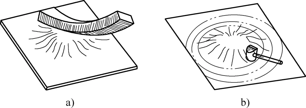
a) Rubber strip slapping the bulged thin plate
b) Hammering around the edges
Next, use a copper or aluminum hammer to hammer around the edges of the bulged area, starting from the edge and proceeding in a tangential direction along the boundary of the bulged area. The hammering should follow a chosen rotational direction and progress systematically.
The farther out the hammering points are, the denser they should be, and they must be as uniform as possible. The purpose of hammering is to induce tangential elongation deformation in the material. The denser the hammer points, the greater the hammer-pressed material beyond the bulged area; the more uniform the hammering, the better the correction effect will be, avoiding new small bulging caused by uneven hammering (see Figure 2b).
It is worth mentioning that the two different correction methods for flattening a bulged plate are complementary to each other. As for how far to go with each method, this depends on the specific bulging extent and the size of the bulged area of the plate. The principle is: each method should perform to its maximum correction potential.
For plates with larger bulges, correction can be done progressively in several steps. After each correction cycle, it is necessary to perform a stress-relief annealing. During each combination of corrections, the sequence of methods remains unchanged, i.e., first the rubber strip for contracting the bulged area, and then hammering around the edges, until the correction requirement is met.
(2) Correction of looseness around the edges
When looseness around the edges results in instability and wavy deformation at the edges of the plate (see Figure 3a), the following method can be used for correction.

a) Wave deformation
b) Breaking down the waves
c) Smoothing the waves with a rubber strip
First, break down the large waves into countless small ones by hammering along the loose edges with a copper or aluminum hammer (see Figure 3b). Then flip the plate over onto the platform and slap the edges with the rubber strip (see Figure 3c), causing material contraction in the loose portions, thereby reducing the height of the large waves.
The purpose of breaking down large waves into many small waves is to convert large wave surfaces into microscopically curved but overall flat surfaces, facilitating contraction deformation via slapping with the rubber strip within the micro-curved surfaces.
After striking around the plate, start from the inside of the loosened area and hammer inward as shown in Figure 4, causing the material to extend circumferentially. This can reduce overall unevenness caused by loosening around the edges. During the hammering of the central area, the closer to the center the hammer strikes, the denser they should be, ensuring uniformity in the overall correction of the plate.
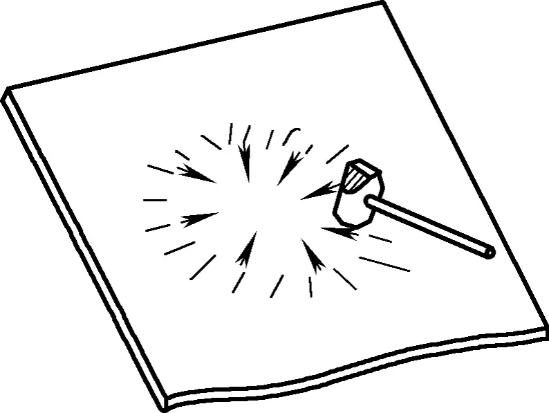
Similar to the correction for eliminating bulging, the two different correction methods mentioned above for eliminating edge looseness are used in conjunction. For larger degrees of looseness, you can also refer to the method for eliminating bulging.
(3) Correction for eliminating looseness around flat holes
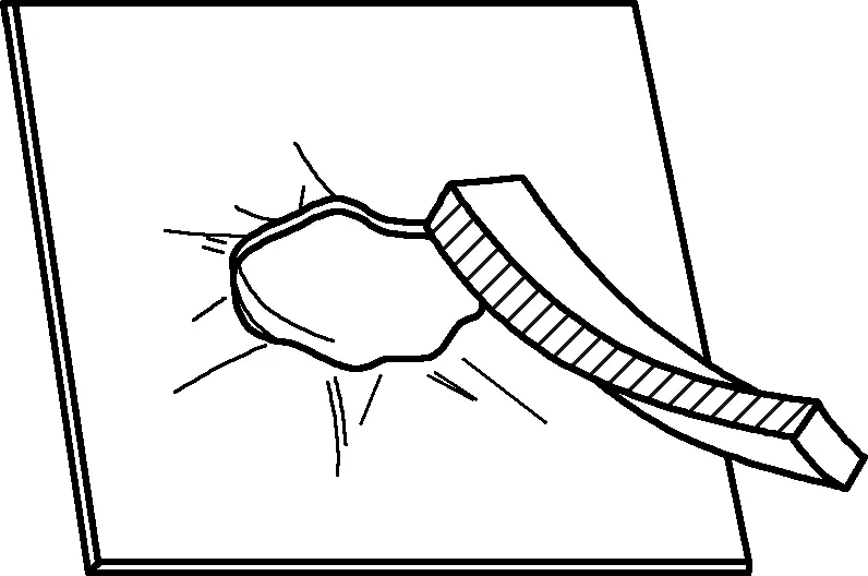
For plates with flat holes, the deformation loosening around the hole can be corrected as shown in Figure 5. This involves using a rubber strip to strike tangentially along the edge of the hole to push the material away, achieving the correction.
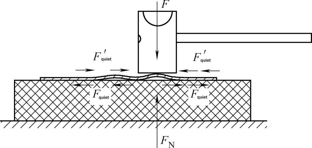
For severely loosened hole edges, the plate can be placed on a rubber cushion, and a copper hammer can be used to strike the raised edges around the hole, causing the material to shrink, which achieves the correction of the plate (see Figure 6). The principle behind this correction is that when the raised edge around the hole is hammered, the static friction between the plate and the rubber cushion, combined with the impact force and the cushion’s counterforce, causes compressive deformation of the raised edge, resulting in the leveling of the hole edges.
(4) Correction for eliminating the “tightening” deformation around reinforced holes
For plates with reinforced holes, such as flanged holes, there’s complex residual stress remaining around the flanged hole, including radial bending moments through the hole’s axis, and tangential compressive stress along the flange edge. This leads to “tightening” deformation at the outer radius of the flanged curve and loosening deformation at the flat outer edge.
To eliminate these deformations, the part is usually placed on a mold with the bent side facing down or on a flat surface with the bent side facing up, using a copper hammer to strike around the hole (see Figure 7). This changes the residual tensile stress distributed within the material around the hole to residual compressive stress, causing the stress at various points around the hole to “relax,” and the surface tends to flatten. The outer edge portion is tapped with a rubber strip to cause the material to shrink and achieve flattening.

a) Stress relief with the bent edge facing down
b) Stress relief with the bent edge facing up
2. Precautions for correction operations
The rubber strip pulling method can cause shrinkage in thin flat material, achieving leveling. However, because the static friction at the moment when the thin plate and the rubber strip make contact is limited, the material to be corrected must have a relatively low yield strength. Even non-ferrous metals must be corrected in the “M” (annealed) state.
When hammering on a platform, the plate part being struck must be fully supported underneath and must not be left hanging. The hammer used should be made of softer material, such as a copper hammer, aluminum hammer, hardwood hammer, or rubber hammer, to avoid leaving hammer marks on the surface of the thin plate. Sometimes, placing a flat plate on the correction spot before hammering it can also help in correcting the material.
When hammering, it is crucial to carefully analyze, select the correct point, and act decisively. More work doesn’t always mean better results. If the points selected are incorrect, over-corrections can occur, ineffective operations can increase, and the internal stress of the plate can even increase, leading to uneven material thickness. This not only drives up costs but also severely affects product quality.
When refining or reducing large undulations around the edges or holes of a plate on a platform, place a rubber pad of appropriate hardness between the undulating plate and the platform. Use a copper hammer or hard rubber hammer with moderate hardness to hit the peaks of the large undulations. Under the combined effect of the rubber pad’s upward reaction force, the friction symmetrically acting on the peak, and the hammer’s striking force, the material between the three stress points at the peak compresses and deforms, reducing the height of the peak or even turning a large peak into two smaller ones.
Always remember that you must not place the workpiece directly on the platform and strike the peak with a hard hammer. This is because the friction between the workpiece and the platform is limited. The material between the three stress points at the peak will not shrink and deform; instead, the local stress caused by direct hammering between the hammer and the platform might cause squeezing and thinning of the material, increasing the wave-like unevenness of the plate.
It should be noted that the manual correction techniques described above for non-ferrous metals are also applicable to the manual correction of thin steel plates.
III. Manual techniques for correcting thick steel plates
Steel plates formed by hot rolling steel ingots with a thickness of more than 4mm are referred to as thick steel plates. Plates 4-25mm thick are typically called medium plates, those above 25mm are called thick plates, and plates thicker than 60mm are known as extra-thick plates. During the rolling process, steel may deform due to residual stress.
The excellent plasticity of metal and the significant transverse stiffness of thick plates, along with the varying elongation between adjacent areas and changes in the internal stress distribution during processing, can all cause deformation in thick steel plates. Common deformations include center bulging and slow bending in thick steel plates.
There are many methods for correcting thick steel plates. Manual correction involves cold correction at room temperature. Since cold correction causes work hardening, it is only suitable for correcting steel with good plasticity.
In cases of severe deformation or if the steel is highly brittle (e.g., alloy steels or steel that has rusted significantly from being left outdoors), cold correction cannot be employed. Hot correction should be used instead, which involves heating the steel to a high temperature of 700-1000°C for correction. Hot correction is used when the steel has severe bending, poor plasticity, or when there is insufficient power equipment for correction.
1. Thick steel plate correction operations
Generally speaking, in steel plates that exhibit center bulging deformation, the plate thickness is not excessively high, and the fibers in the deformed area are slightly longer than those in the surrounding material. The fibers remain consistent along the plate’s thickness. For center bulging deformation in thick steel plates, the manual correction method involves positioning the steel plate on a work platform with the bulge facing upward, as shown in Figure 8.

Apply pressure on the upper surface of the deformed area (you can also use a press). Since the surrounding material has greater rigidity in the plane direction, the deformation area’s stress resembles that of an arched beam under transverse load, causing the fibers to shorten, thereby achieving the leveling effect. The smaller the deformed area and the thicker the plate, the more apparent and reliable the correction effect.
For thinner thick plates, you can place a pad in the deformed area (the purpose of this pad is to prevent large hammering forces from leaving hammer marks on the steel plate’s surface) and use a hammer to directly strike the bulge, causing the fibers to undergo the same deformation and thus leveling it.
For larger center bulges in thick plates, where the fibers in the deformed area have undergone excessive elongation and the rigidity of the surrounding material has decreased, when applying pressure as before, the fibers in the deformed area will only slightly shorten and press against the platform. This causes the surrounding materials to push outward. Although the deformed area may stick to the platform, the surrounding material stretches slightly and tilts upwards, resulting in new deformation, as shown in Figure 9b.
Therefore, the better correction method is to first use the flame correction point heating method (see Figure 9a), which causes some shrinkage in the bulging fibers, reducing the height of the bulge. Then, divide the bulge into several smaller areas and use manual correction methods to level each small bulge, eventually achieving a flat plate.

a) Distribution and order of heating points
b) Elimination of ripples
When slow bending occurs in thick steel plates, the correction method is as shown in Figure 10. First, place the deformed steel plate on a work platform with the concave side facing up, and place an iron block on the concave side of the thick plate (see Figure 10a). Then, hammer the concave side of the steel plate, moving the iron block evenly in the direction of the arrow S in Figure 10b.
Use a small amount of force to strike the iron block. Given that the area of contact between the upper surface and the iron strip is small, the compressive stress produced by hammering is relatively large. The fibers in the concave area will gradually elongate, causing the concave surface to deform in the opposite direction and achieve correction.
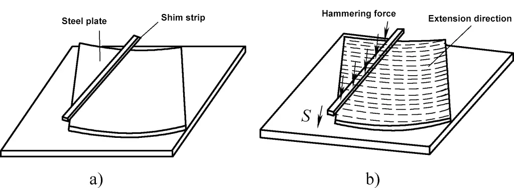
a) Placement of thick plates during correction
b) Hammer correction
2. Precautions for correction operations
For moderately thick plates with modestly deformed areas and a central bulge, due to the large bending rigidity, the deformation under larger external loads includes only a small amount of elastic deformation, making the deformation effect more significant. Therefore, it is suitable to use a correction method with larger loads. When large-pressure equipment is available, effort should be made to use the equipment to apply force to reduce the labor intensity of the operator; otherwise, a shim can be used, and a sledgehammer can directly strike the bulge of the steel plate.
For steel plates that are not very thick or thick plates where the deformed area is much larger than their thickness, because their bending rigidity is not very high, they can produce some deformation under external loads, but this includes a certain amount of elastic deformation, making it difficult to achieve a completely flat correction.
If the hammer strikes too many times, the thick plate, impacted instantly by the platform and sledgehammer, can cause the material fibers to elongate, exacerbating the bulging deformation. In such cases, the flame heating method should be first used to reduce the bulging deformation, turning the large-scale deformation into several smaller areas of slight bulging deformation, and then the aforementioned correction method can be used to correct the bulging deformation of the thick plate.
For various bending deformations of thick plates, if they are relatively thick and the deformed areas are also quite large, the thermal correction method should be used first to reduce the amount of deformation. Large area deformations should be divided into smaller deformations, and then manual correction should be applied.
For any complicated deformation of thick plates, the first step is to correctly analyze the cause and location of the deformation. For each deformed part that needs correction, it is important to flexibly apply various correction methods according to the specific situation.
In cold corrections, sledgehammers are often used. The hammer strike points should be accurate, and the hammer marks should be even to avoid leaving noticeable hammer imprints on the steel plate’s surface that could affect its surface quality. When larger striking force is needed, shims should be appropriately added.
When holding a sledgehammer, gloves should not be worn to avoid slippage, which could cause the hammer to fly out and lead to accidents or danger. Before using the sledgehammer, check whether the hammer handle or head is loose, whether there are cracks, and whether there are burrs or edge rolling on the hammer head. Any defects should be repaired before use.
IV. Techniques for Manual Correction of Profiled Materials
Like other sheet metal materials, the materials (usually angle steel, channel steel, etc.) and other shaped profiles used in sheet metal processing are also prone to deformation during production and processing, so corrections are also necessary. For different profiles, the manual correction methods vary.
1. Correction of Bent Angle Steel Parts
Bent angle steel parts are divided into sheet steel angle and hot-rolled angle steel. The former is angle steel made from sheets of steel pressed according to the needs of sheet metal components (hereinafter referred to as “sheet steel angle”). The latter is angle steel shaped directly by hot rolling from steel ingots (hereinafter referred to as “angle steel”).
Since angle steel parts have two vertical edges and are often long, they are prone to a variety of deformations. Common deformations include outward bending, inward bending, twisting, uneven single sides, and angular deformations (see Figure 11).
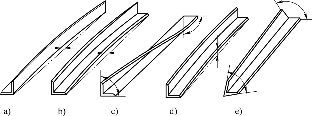
Due to differences in rolling methods and cross-sectional sizes, the mechanical properties of the two aforementioned types of angle steel vary significantly. Their deformations and corresponding correction methods also differ.
(1) Correction Operations for Angle Steel
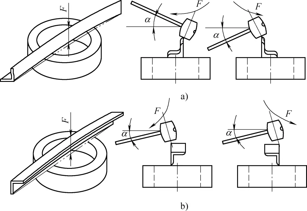
Bending deformation is the most common issue with angle steel. During correction, a suitable steel ring can be selected. The angle steel is placed on the ring with the convex part of the bent section facing upwards and positioned between the two support points of the steel ring. The convex part of the bending area is hammered at its vertical edge, forcing the angle steel into a reverse bend to achieve correction.
1) Correction of Angle Steel Outward Bends.
When correcting an outward bend of angle steel, its side should be laid flat on the steel ring, and the vertical bending edge of the angle steel should be perpendicular to the end face of the ring, with the convex part facing upwards. To prevent the angle steel from flipping during hammering, the hammer handle should be slightly raised or lowered at about a 50-degree angle (α angle). At the moment of impact, apply force not only downward but slightly inward (when the rear hand raises the hammer) or outward (when the rear hand lowers the hammer). This angle depends on the hammerer’s standing position, as shown in Figure 12a.
2) Correction of Angle Steel Inward Bends.
When correcting an inward bend, angle steel should be placed with its back side facing upwards, and the vertical bending edge should be perpendicular to the support end of the steel ring. The hammering should then be done to correct the bent area. To prevent the angle steel from flipping during hammering, the height of the rear hand holding the hammer should also be slightly adjusted, as shown in Figure 12b, where the angle (α) is about 50 degrees. During the impact, a slight inward or outward pulling force should also be applied.
a) Outward Bends of Angle Steel
b) Inward Bends of Angle Steel
3) Correction of Twisted Angle Steel.
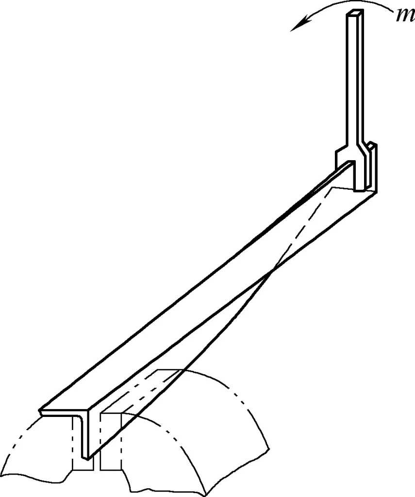
To correct twisted angle steel, apply torque in the opposite direction of the twist until reverse deformation occurs, thus achieving correction. This method involves clamping one end of the angle steel in a vise, gripping the other end with a wrench, and twisting it in the reverse direction, as shown in Figure 13. Once the twist is eliminated, hammering can be used to flatten and correct the edges of the angle steel.
4) Correction of Angular Deformations in Angle Steel.
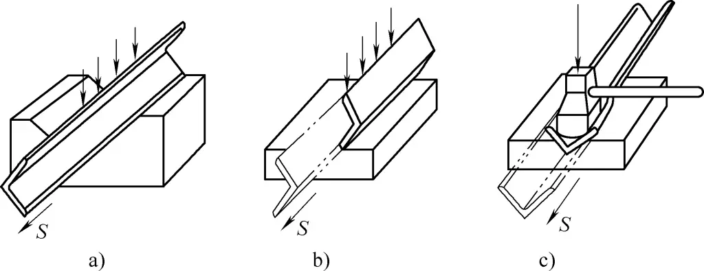
When the angle of angle steel is greater than 90 degrees, place the angle steel in a V-shaped groove and hammer the outer inclined part to correct it. You can also place the steel with its edge slanted on a platform and hammer down to reduce the angle, as shown in Figures 14a and 14b.
a), b) Correction of angles larger than 90 degrees in angle steel
c) Correction of angles smaller than 90 degrees in angle steel
Hammering should start from one end of the angle steel, making correction easier and allowing for clear observation of the results. Corrected sections should be gradually moved off the platform, and when more than half of the total length is corrected, the angle steel should be flipped, and the opposite end should be corrected until the whole length is straight.
When the angle of the steel is less than 90 degrees, place it flat on the platform, and use a shaped hammer to strike the inner side of the angle to increase the angle, as shown in Figure 14c.
5) Correction of Uneven Single Sides in Angle Steel.
When angle steel experiences uneven single-sided deformation, the uneven side is typically placed flat on the platform and hammered to correct it. During hammering, alternate between the uneven surface and the vertical edge.
6) Correction of Combined Deformations in Angle Steel.
If an angle steel shows several types of deformation, with varying degrees, correct the areas with the greatest deformation first, then gradually work on the areas with lesser deformation. If the deformation consists of a combination of several basic types, the proper correction sequence is: start with twisting, then proceed to angle correction, and finally correct any bending or single-sided unevenness.
Due to the possibility of new deformation caused by limitations of corrective methods or improper operations during various corrections, this process may need to be repeated multiple times to meet the correction requirements.
(2) Correction operation of plate-made angle iron.
Compared with regular angle iron, plate-made angle iron has thinner thickness and much lower stiffness at the bent corners, which makes the plate-made angle iron more prone to deformation. The correction of its deformation clearly exhibits the characteristics of sheet metal processing.
1) Correction of twisting in plate-made angle iron.
During the correction of twisting, since the plate-made angle iron has low torsional rigidity, for small workpieces, significant corrective effects can be achieved simply by twisting back by hand.
When applying force, simple section clamps should be made at both ends of the twisted workpiece. Since the clamps have certain rigidity, when torque is applied, the cross-section at both ends of the plate-made angle iron will not deform. For the correction of twisting in more rigid plate-made angle iron, the method shown in Figure 13 can be used, where the twist is corrected using a wrench mounted on a bench vise.
Since the rigidity of plate-made angle iron is lower than that of hot-rolled angle iron, when applying torque, uncoordinated actions may cause new bending deformation, or even lead to the destabilization of the workpiece, resulting in more complex deformations.
2) Correction of bending in plate-made angle iron.
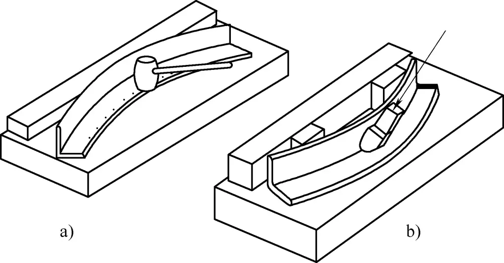
When a plate-made angle iron undergoes inward bending deformation, the bent surface should be placed flat on a platform, and hammering should begin from the innermost edge of the most severely bent area. Due to the relatively large width-to-thickness ratio and the thinner plate thickness, the hammering of the inner edge has a more noticeable corrective effect on the inward bending. At the same time, the unevenness of the other perpendicular edge should also be corrected alternately until both sides of the plate-made angle iron are straight, as shown in Figure 15a.
a) Correction of inward bending.
b) Correction of outward bending.
When a plate-made angle iron undergoes outward bending, the leg with the bend should be placed flat on the platform, then a gauge block should be placed between the bent edge and the vertical stop surface, and a wood wedge should be used to hammer the inner bend edge toward the vertical stop surface. This extends the longitudinal fibers at the bend due to hammering while also applying a lateral load to the bent edge, causing a reverse bending to correct the deformation.
It should be noted that the angle of the wooden wedge should be half a degree smaller than the angle of the workpiece. The radius of the wedge should match the inner radius of the bent angle iron, and its width should be 2 to 3 times its thickness, as shown in Figure 15b.
3) Correction of angular deformation in plate-made angle iron.
When the angular deformation of the plate-made angle iron is too large, as shown in Figure 16a, place the angle iron with its opening facing upward on a V-shaped groove. Use the R section of a wooden wedge to hammer the inner R area of the angle iron, gradually reducing the angle. Hammering usually starts from one end and extends progressively toward the middle. Before correction, make an angle template for frequent use during the process.
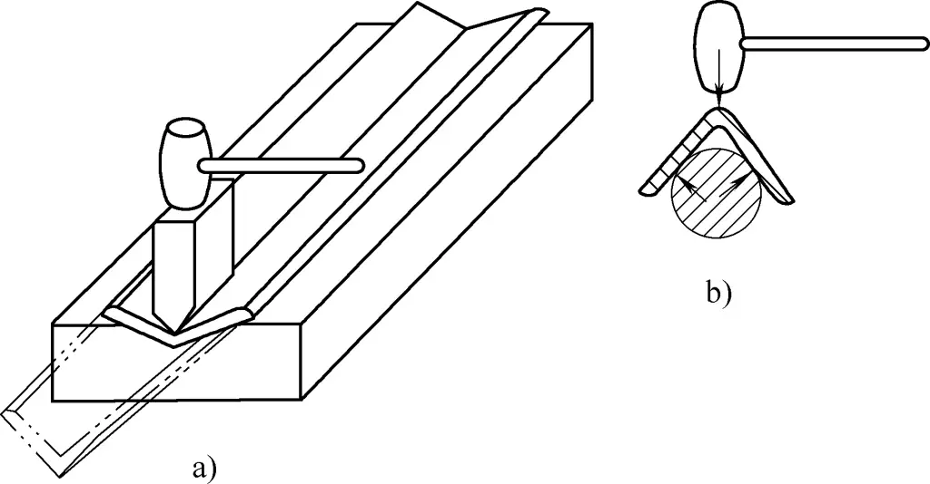
a) Reducing the angle.
b) Increasing the angle.
For the correction of larger angular deformations in longer plate-made angle irons, follow the method shown in Figure 15b, but remove the spacer blocks. Place both sides of the angle iron against the platform surface and the vertical stop surface, and hammer according to the direction shown in Figure 15b to reduce the angle.
When the angular deformation of a plate-made angle iron is too small, you can place the inner surfaces of the angle iron against a round steel bar. Under the external force shown in Figure 16b, both sides of the angle iron will tend to rotate around the vertex, thereby increasing the angle and achieving the correction.
4) Correction of unevenness on one side of plate-made angle iron.
The deformation caused by the elongation or shortening of the bending line, or the instability of the two planes beside the bending line, is referred to as uneven deformation in plate-made angle iron, as shown in Figure 17. Figure 17a shows deformation caused by the shortening of the bending line, while Figure 17b shows deformation caused by elongation of the bending line.
The common feature of these deformations is that both planes of the plate-made angle iron become curved and uneven. During correction, the adhesion between the two planes and the platform should be checked first. If the middle is hollow, it’s the deformation shown in Figure 17a; if the ends are hollow, it’s the deformation shown in Figure 17b.
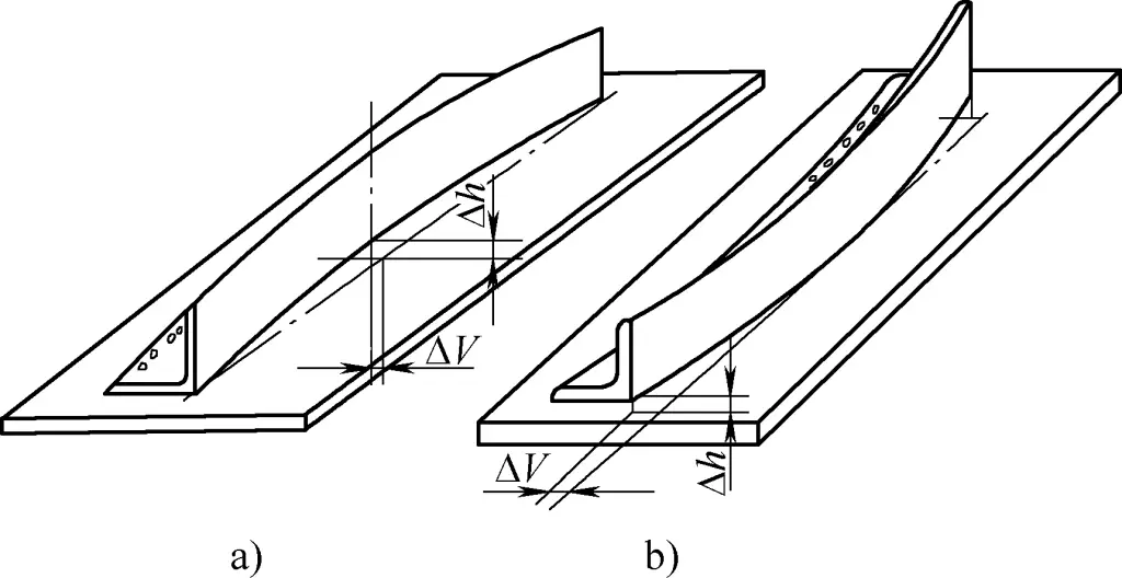
a) Deformation caused by shortening of the bending line.
b) Deformation caused by elongation of the bending line.
One method to correct the inner deformation shown in Figure 17a is to use the method shown in Figure 15b to alternately correct the bending on both sides. Another method is to use the V-shaped groove shown in Figure 16a, with the angle iron’s opening facing upward. Use a wooden wedge smaller than the inner angle to hammer along the bending line inside the R section of the angle iron, gradually extending it axially to achieve correction. A third method is to cause shortening deformation at the outer edge of the plate-made angle iron’s fibers, such as through the use of a shrinkage machine or flame correction.
For the deformation shown in Figure 17b, the common correction method is to alternately hammer the outer edges of both sides, causing the outer edge fibers to elongate. When the bending line and the outer edge fibers exhibit the same deformation, the plate-made angle iron becomes flattened and straightened.
Finally, if there are local uneven spots on the bent edge, you can gently press the surface of the plate on the platform by hand, pinpoint the uneven spots, and gradually eliminate them.
(3) Precautions for correction operations.
The cross-sectional shape and dimensional characteristics of single-edge bent parts determine their susceptibility to deformation, but also indicate that large external loads are not necessary for the operator to achieve correction.
During correction, it is important to use rigid flat clamps when applying torque, especially for plate-made angle iron. Otherwise, section deformation or localized unevenness and bending may occur at the loaded end. When performing manual correction, the hammering points in the correction area must be evenly distributed, and excessive concentration should be avoided to prevent localized material hardening or even cracking.
Additionally, when hammering for correction, the underside of the workpiece must be well-supported. It is strictly forbidden to apply force on only one side of the straight edge of the angle iron to avoid creating unevenness or affecting the results of the hammering. Hammer strikes should be applied to both sides alternately, to prevent localized material hardening and preserve surface quality. The hammering points must be chosen carefully, accurately, and effectively, with as few points as possible. The material of the hammer used should be softer than steel, such as a copper, aluminum, or hardwood hammer.
2. Correction operation for channel steel.
The cross-section of channel steel is made up of a web and two symmetrical flanges connected to the web. Compared to angle iron, channel steel is much stiffer, so correcting it requires more effort. However, since the cross-section of channel steel is symmetrical, its deformation is slightly easier to address than that of angle iron.
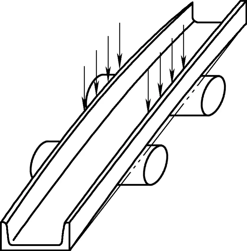
Types of deformation in channel steel include vertical bending, lateral bending, and twisting, as shown in Figure 18. Bending within the plane of the web is called vertical bending, while bending in the direction of the flanges is called lateral bending.
Since the height dimension of the web is larger than the width dimension of the flange, the likelihood of lateral bending deformation in a channel steel is greater than vertical bending. Moreover, from the perspective of correcting deformation, the adjustment required for vertical bending is far greater than that for lateral bending.
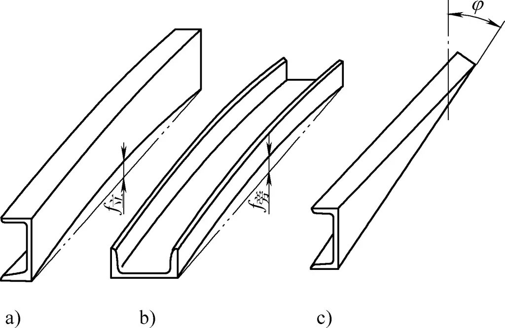
a) Vertical bend
b) Lateral bend
c) Twist
(1) Correcting deformation of channel steel
Due to the physical demands, manual correction of deformed channel steel is only suitable for smaller sizes, while larger channel steels must be corrected using mechanical methods.
1) Correction of vertical bend deformation in channel steel.
When correcting vertical bend deformation in channel steel, place the channel steel on a makeshift correction table composed of two parallel round steels, with the convex part facing upwards. Strike the web plane with a heavy hammer, as shown by the arrows in Figure 19. This allows the striking force to transfer from the upper to the lower part of the web.
The combination of the web and flange has a rounded transition with substantial local rigidity, which helps prevent local deformation in the flange during hammer strikes.
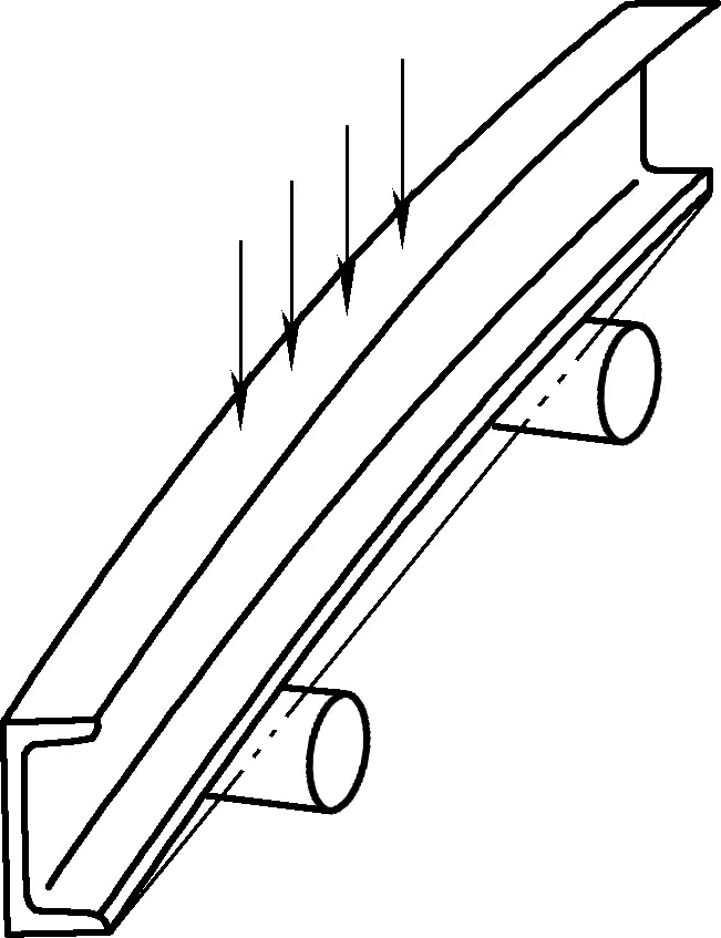
2) Correction of lateral bend deformation in channel steel.
Lateral bending of channel steel can be either outward bending or inward bending. The correction method for outward bending is to place the convex part of the flange facing upwards (see Figure 20), positioning it on a simple correction table composed of two parallel round steels. Strike the outer edge of both flanges alternately and symmetrically with a heavy hammer. This corrects the vertical bend deformation of the flanges, which in turn makes it easier to correct the lateral bend in the web, thereby correcting the overall outward bend of the channel steel.
When the channel steel has inward bending deformation, and the inward bend covers a longer section with slight curvature, the channel steel can be placed horizontally on a platform. Hammer the web on both sides of the flanges to correct the vertical bend of the flanges, as shown in Figure 21.
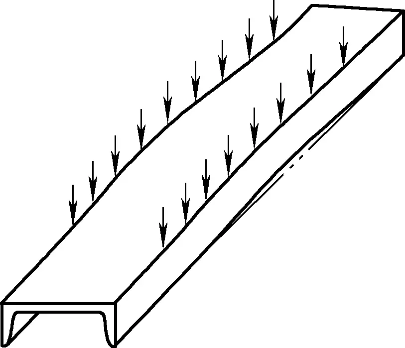
It might be necessary to flip the channel steel, as shown in Figure 20, to correct the reverse bend in localized areas. Once the lateral bend of the flanges is corrected, the overall deformation of the channel steel will also be corrected.
If the inward bend deformation of the channel steel is a small-scale but severe bulging, flame correction is preferable, as excessive hammering may lead to section distortion and negatively impact surface quality.
3) Correction of twisting deformation in channel steel.
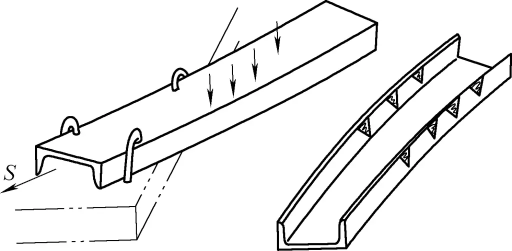
To correct twisting deformation in channel steel, first place the steel diagonally on a platform with the twisted part extending beyond the platform. Then, clamp the channel steel in place and hammer the raised side that extends beyond the platform to twist it in the reverse direction. As the hammering continues, move the channel steel further onto the platform (in the direction S shown in Figure 22a), and then flip it around and repeat until it is fully straightened.
a) Cold correction
b) Hot correction
Twisting in channel steel is often combined with bending, which makes correction more challenging. Figure 22b shows a combined deformation of both twisting and bending caused by unequal vertical bends in the two flanges. The usual correction method is to mark flame heating points of varying numbers on both flanges based on the degree of twisting. The flange with greater vertical deformation should have more heating points, and the one with less deformation should have fewer.
During flame heating, it’s best to heat the points on both flanges simultaneously to produce even corrective deformation. If the selection of points and operation are done correctly, satisfactory correction results can be achieved with a single heating. Finally, manual adjustment can be applied to completely eliminate the original deformations.
4) Correction of other deformations in channel steel.
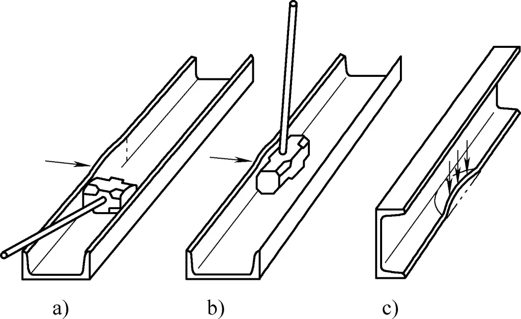
As shown in Figures 23a and 23b, when local deformation appears on the flange of the channel steel, a heavy hammer can be placed against the flat area near the convex part. Alternatively, an entire heavy hammer can be placed horizontally behind the convex portion, while a second hammer strikes the outer surface of the convex area. This compresses the bent fibers, straightening them and flattening the flange.
a) Hammer placed vertically against the flange
b) Hammer placed horizontally against the flange
c) Correction of concave flange
If there is a local depression in the flange, the flange can be laid flat with the deformed side against the platform. Hammer the raised portion of the depression to remove the local protrusion (as shown in Figure 23c). If the depression is inward, and hammering is difficult, use a suitable tool such as an anvil or another long tool to indirectly apply force to the raised part to flatten the deformation.
(2) Precautions in correcting channel steel
The cross-section of channel steel consists of a relatively wide web and two flanges symmetrically distributed relative to the web. The key to correcting vertical bend deformation lies in correcting the vertical bend of the web, while the key to correcting lateral bend deformation lies in correcting the vertical bend of both flanges. Unequal vertical bending in the two flanges leads to twisting of the channel steel. Any analysis of channel steel deformation and choice of correction plan should be based on this understanding.
Since the width of the flanges is much less than that of the web, the small bending stiffness in the width direction of the flanges means that lateral bending deformation is more likely to occur. At the same time, due to the low stiffness, lateral bend deformation is relatively easier to correct. For any complex deformation in channel steel, the correction sequence should be: Twist → Vertical bend → Lateral bend.
When correcting channel steel, note that because the edge thickness of the flanges is relatively small, and the strength of the two right-angled edges is also lower, hammering parallel to the flange surface may cause localized damage due to the small contact area.
Therefore, when force is applied to these areas, it is best to use an anvil with a suitable width or apply a proper forming hammer, ensuring that the flanges and edges don’t directly come into contact with the hammer. This evenly distributes the force, reducing compressive stress and avoiding hammer marks. Hammering directly onto stressed parts should be avoided.
3. Correction of frame-plate type components
Components made from thin sheet materials pressed to form a frame-like structure with certain mechanical properties on one plane are called frame-plate type components. Based on their shape, frame-plate components can be classified as strip-like, ring-like, or rib-frame types. The main components of frame-plate parts are the web and the rim.
Due to the different forming processes, especially the different forming methods of the rim, the elongation and contraction of the material fibers vary, resulting in various deformations in frame-plate type components.
For example, strip frame components may exhibit bending, unevenness of the web plane, and twisting, along with increased rebound of the rim angle. Ring frame components may show web warping and increased rebound of the rim angle. Rib-frame (or large frame plate) components may exhibit web unevenness (twisting and inaccurate rim shape).
(1) Correction of frame-plate type components
Panel-type components belong to thin plate forming parts. Since they are thin plate products, their local rigidity is small. Generally, for the local deformation of panel-type components, the deformation can be directly corrected, but for some larger deformations, a comprehensive analysis of the associated parts is required to find the cause.
1) Correction operations for strip-type panel components.
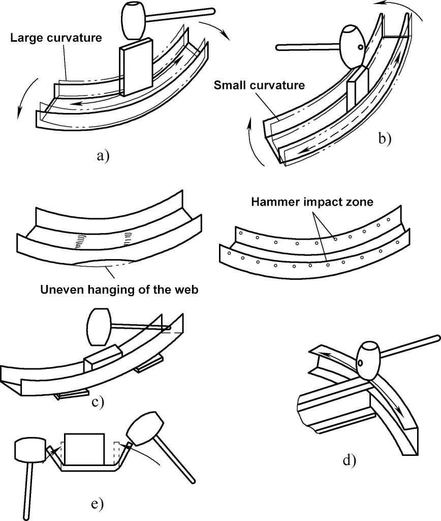
As shown in Figure 24, the deformation and correction of strip-type panel components are illustrated. When the strip panel has a curvature that is too large (i.e., the radius of the arc is too small) (see Figure 24a), the correction method is to place the web of the strip panel flat on a platform and use a strip of a certain width-to-thickness ratio to strike along the inner edge bending line of the panel evenly, thus extending the fibers near the inner edge and reducing the curvature.
a) Correction of reduced curvature
b) Correction of increased curvature
c) Correction of web center being suspended in midair
d) Correction of web end warping
e) Correction of bending angle
When the strip panel has a curvature that is too small (i.e., the arc radius is too large) (see Figure 24b), the correction method is to place the web of the strip panel flat on a platform and use a strip of the same type to strike along the outer edge bending line of the panel evenly, extending the fibers near the outer edge and thus increasing the curvature.
When the strip panel has the deformation of a locally suspended web area (see Figure 24c), the web of the panel should be placed flat on a platform, and thin plates should be placed at both ends of the deformed area. A block narrower than the width of the inner edge should be placed on the deformed area so that the sides of the block are tightly against both edges of the panel. Use a hammer to strike, leveling the raised edges, then remove the thin plates and continue using the block and hammer to eliminate unevenness in the web.
When the strip panel’s end warps causing the web to become uneven (see Figure 24d), you can place supports under the inner sides of both edges of the strip panel. Strike evenly along the edges’ line to extend the fibers, thereby correcting the web’s flatness.
When the strip panel has spring-back deformation in the bending angle (see Figure 24e), use a hammer to directly strike the edge where the deformation angle has increased, or use a block clamped against the bending line of the panel, and strike along the outer edges and the roots of the bending line. This will press the deformed edges against the block to achieve angle correction.
2) Correction operations for ring-type panel components.
Since the edge panel of the ring panel is a closed, thin plate structure perpendicular to the web, it forms a structure with considerable stiffness together with the web. Any deformation or stress distribution in one part will inevitably affect the stress distribution in other parts, potentially causing deformations.
When the web of a ring panel has a warping deformation where both sides are raised (see Figure 25a), the correction method is to place the concave side facing down on a platform’s edge. Hold the left side of the panel down with your left hand and press the right side down with your right hand, bending the edge panel and flattening the web. Then, turn the panel over with the concave side facing up, and with the web touching the platform (as shown in Figure 25b), use a block to strike along the inner edges of the bending line, especially at the joints on the left and right, to eliminate shear stress and tensile stress and increase compressive stress near the bending line.
After correcting the web, you should also appropriately adjust the connections at both sides of the edge panel, minimizing any residual tensile stress in the deformed areas after correction.
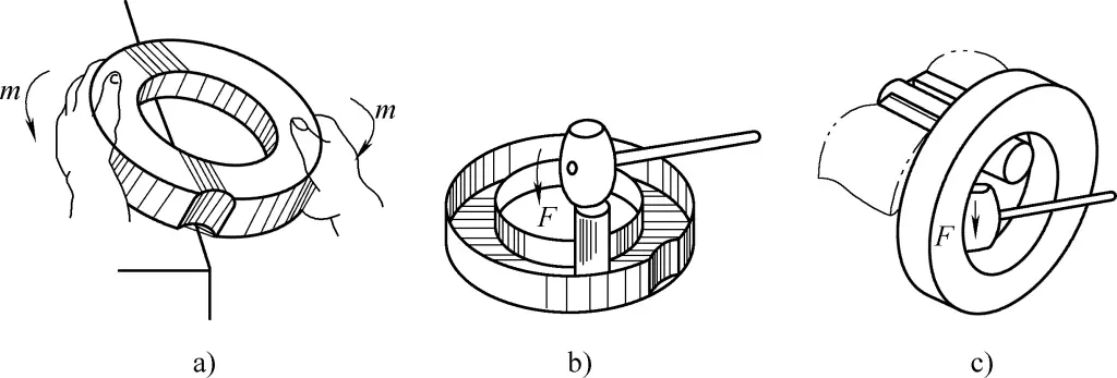
a) Manual correction of web warping
b) Hammer correction
c) Correction of the inner ring panel
When the inner and outer edges of the ring panel exceed the required shape (see Figure 25c), clamp the curved wood section in a vice, suspend the part below the outer shape of the component, and hammer the deformed area to achieve the shape correction. Alternatively, as shown in Figure 25b, you can turn the concave side up and adjust the edge angles (as shown in Figure 24e) to achieve the shape adjustment.
3) Correction operations for large panel components.
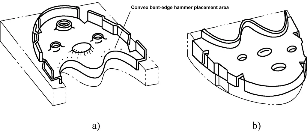
As shown in Figure 26, large panel components (also called frame-type panels) exhibit features such as flanged edges, reinforcing holes, and stiffening recesses that enhance planar rigidity. The edge panels also contain structural cutouts and recessed areas to accommodate connecting parts.
a) Front view
b) Back view
For such complex structural components, various warps and uneven deformations inevitably occur after heat treatment. Common deformations are relaxed and expanded bent edges at cutouts, shrinking and tightening around reinforcing holes, looseness around flat holes, planar twisting, and increased curvature of concave bent edges.
The correction process for large panel components is as follows: Place the deformed component (see Figure 26a) on a mold after heat treatment. First, use rubber strips to hit the web about the flat areas to make it generally conform to the mold.
Use a non-ferrous metal hammer or hardwood mallet to tap the base of reinforcing recesses and lightening holes (use a block to hammer against these areas to prevent damage). The purpose of hammering is to relieve tensile stress and increase compressive stress. Then flip the component over and place it on another mold with the back facing up (see Figure 26b), where you will use the same mallet or hammer to strike around the bases of reinforcing recesses and lightening holes, or use a non-ferrous metal block to press against these areas.
Use rubber strips to consistently tap the web to flatten any unevenness. If the web shows signs of bulging or twisting, correct it as you would for a flat plate. Since the material’s elongation at the concave bent edge during flanging is the greatest, place the component back on the mold (as shown in Figure 26a) and hammer the concave bent edge evenly until the material relaxes and matches the template.
(2) Precautions for correcting panel components
The main structural elements of a panel are the web and edge panels. Regardless of any local structures on the web (such as flat holes, reinforcing holes, or local forming features), at least one side of the web must remain flat. Regardless of any cutouts or local forming on the edge panel, the edge panel must always be perpendicular to the plane of the web. Therefore, all corrections must be carried out on a platform.
For more complex, large panel components, templates must be used for correction to ensure that the component’s shape is as close as possible to the correct form. Correcting without a mold is strictly prohibited, as excessive ineffective corrections can worsen deformation, leading to irreparable distortion.
When correcting simpler panel components, the web should always remain flat against the platform surface. When hammering the fibers of the web or bending lines, the platform must be used as a solid base. The area being hammered must be firmly supported — hammering without support is strictly prohibited, as this could not only fail to modify the fiber length but also introduce new unevenness.
During the correction of large flat surfaces, the flat side should be placed against the mold or platform, with the uneven side facing upwards. This facilitates the application of the rubber strip for leveling. Meanwhile, the corrected portion of the web should be in contact with the mold plane and not be suspended, to make it easier to use the hammer and to prevent new dents from forming due to the application of the rubber strip. When the area being struck is small or requires greater accuracy, a wedge block can be used to target the area.
For large warping deformations of frame panels, torque can be applied in the opposite direction of the deformation to reduce the original deformation level. Then, hammering can be used for meticulous correction until it meets the drawing specifications.
To ensure the exterior quality and shape accuracy of the frame panel, avoid using hammers or blocks made of hard materials in direct contact with the workpiece surface to prevent leaving marks. For the web-to-frame edge connections that are difficult to apply external forces, softer blocks or tools shaped to fit the contour must be used to apply indirect force. This prevents inaccuracies in force application or mutual interference between parts from damaging the correction outcome.

