I. Mechanical Properties of Materials
The mechanical properties of materials refer to a series of mechanical characteristics exhibited by materials under the action of force, reflecting their ability to resist deformation or damage under various forms of external forces.
1. Strength
Strength is the ability of a material to resist plastic deformation and fracture under external loads. In engineering, yield strength and tensile strength are commonly used, which can be measured through tensile tests.
- Yield strength: The yield limit when metal materials experience yielding, measured in MPa;
- Tensile strength: The ability of a material to withstand tensile forces, measured in MPa;
- Compressive strength: The ability of a material to withstand compressive forces, measured in MPa;
- Bending strength: The ability of a material to withstand bending forces, measured in MPa;
- Shear strength: The ability of a material to withstand shear forces, measured in MPa.
2. Hardness
Hardness is the resistance of a material to plastic deformation, scratching, wear, or cutting, and is the ability of a material to resist the indentation of objects that do not cause permanent deformation under certain conditions.
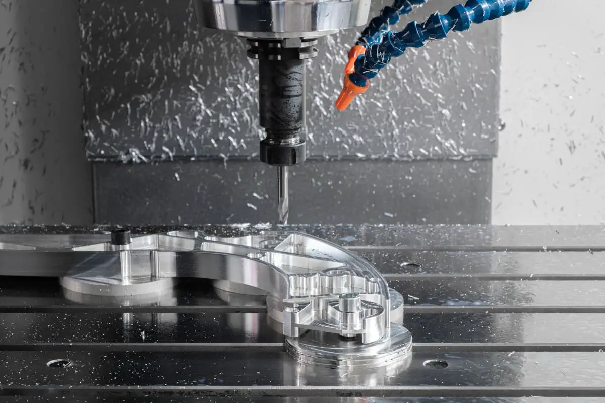
Various machining processes in mechanics are carried out by selecting tools of different hardness according to different material properties.
Hardness includes Rockwell hardness (HR), Shore hardness (HS), Vickers hardness (HV), and Brinell hardness (HBW), among others.
3. Plasticity
Plasticity is the ability of a material to undergo plastic deformation without fracturing under external forces.
Common plasticity indicators used in engineering are elongation and reduction of area. Elongation is the percentage ratio of the elongation of the sample after fracture to its original length, denoted by the symbol A.
Reduction of area is the ratio of the reduced cross-sectional area after fracture to the original cross-sectional area, denoted by Z. The larger the elongation and reduction of area, the better the plasticity; conversely, the poorer the plasticity.
4. Impact Toughness
The ability of a material to resist impact loads is called impact toughness, expressed as impact toughness ak (unit: J/cm2 ) or impact absorption energy Ak (unit: J).
5. Fatigue Strength
Fatigue strength or fatigue limit is the maximum stress at which a metal material does not fail under an infinite number of alternating load cycles. In practice, it is impossible to conduct infinite alternating load cycle tests on metal materials.
Generally, in testing, it is specified that: the maximum stress at which steel does not fracture after 107 cycles and non-ferrous metals after 108 cycles of alternating loads is called fatigue strength. When the applied alternating stress is a symmetrical cyclic stress, the resulting fatigue strength is denoted by S.
II. Mechanical and Technological Property Tests
Material tests provide information about the changes in engineering material properties under external forces (such as tension, compression, bending, torsion, shear, flexure). The strength properties of materials vary depending on whether the applied load is static (low material deformation rate) or dynamic (high material deformation rate).
1. Test
A plastic specimen experiences stress under increasing tensile force. The specimen elongates, and when the tensile force increases to a certain value, the material fractures (static load).
If the material is subjected to a sudden impact force that produces stress, it fractures as if cut by a knife (dynamic load). The purpose of the test is to determine the material’s strength, hardness, machinability, deep drawing properties, as well as bending, forging, and welding properties.
2. Workshop Material Test
The purpose is not to obtain test data, but only to provide data for understanding material processing properties.
3. Formability
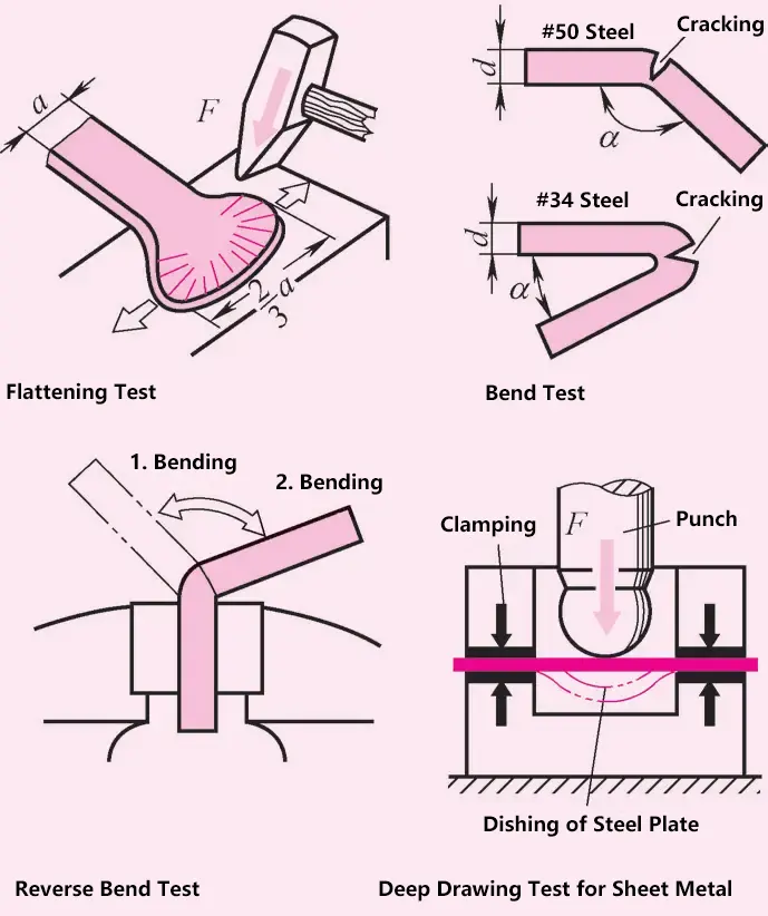
Heat and forge a flat steel bar until cracks appear at the edges. After forging, the width of the flat steel should increase by 1 to 1.5 times the original width without the material cracking.
4. Cold Forming
Cold forming refers to processing methods such as shearing, bending, and stretching of materials without heating. Cold forming processes include cold heading, cold rolling, and die forging.
5. File Test
The file test shows that steel with high hardness is difficult to file.
6. Deep Drawing Test
A clamped steel plate is gradually depressed under the action of a circular punch, with increasing pressure until cracks appear in the steel plate.
7. Spark Test
By observing the spark phenomena produced when grinding steel, one can determine which type of steel it is.
8. Tap Test
Suspend a steel part (mainly cast iron) freely, then tap it lightly to distinguish between cast steel (clear sound), gray cast iron (dull sound), and castings with cracks and shrinkage cavities.
9. Visual Inspection
Inspect surface quality to identify external defects (shrinkage cavities, cracks, and notches).
Material Testing Methods
| Mechanical Testing Methods | Metallographic Testing Methods | Non-Destructive Testing Methods |
| Determine the strength properties of materials under external forces and when stress is generated | Understand the structure and types of metal microstructures | Determine material composition and defect (cracks, voids, inclusions) locations |
| 1) Technological property tests 2) Static load tests 3) Dynamic load tests 4) Creep tests | Study polished samples under a microscope (test piece) under microwave changes structure | 1) Spectral analysis 2) X-ray inspection 3) Ultrasonic inspection 4) Magnetic particle inspection |
10. Tube Expansion and Flaring Test
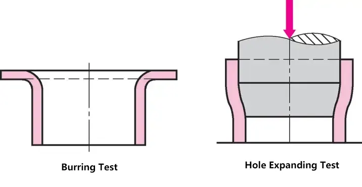
Determine whether tearing occurs at both ends when expanding the tube. For the flaring test, the tube edge is turned outward until cracks appear.
11. Determining Material Hardness by Comparing Indentations
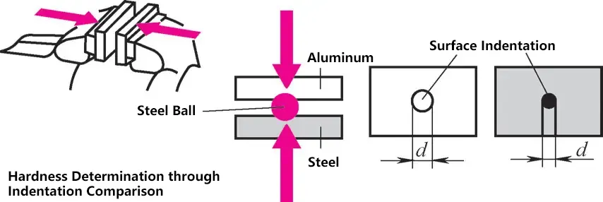
Place a steel ball between two metal plates of different hardness (such as steel and aluminum) and clamp them together in a bench vise. The surface indentation diameters will differ, allowing for comparison of the hardness of the two metal plates.
12. Determining Hardness by Rebound Method
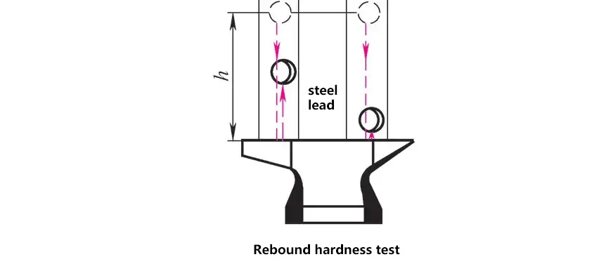
Utilize elastic deformation. A steel ball is dropped from a certain height; materials with higher hardness will have a greater rebound height, while softer materials will have a smaller rebound height.
III. Tensile Test
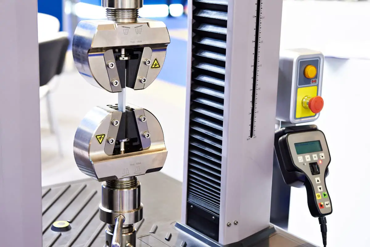
Standard test bars are used for tensile testing. The load is gradually increased. Under the action of external force F, the cross-section of the test bar is subjected to tensile stress, the specimen is elongated, and finally breaks in the middle. External tensile force F (N), elongation Δl (mm).
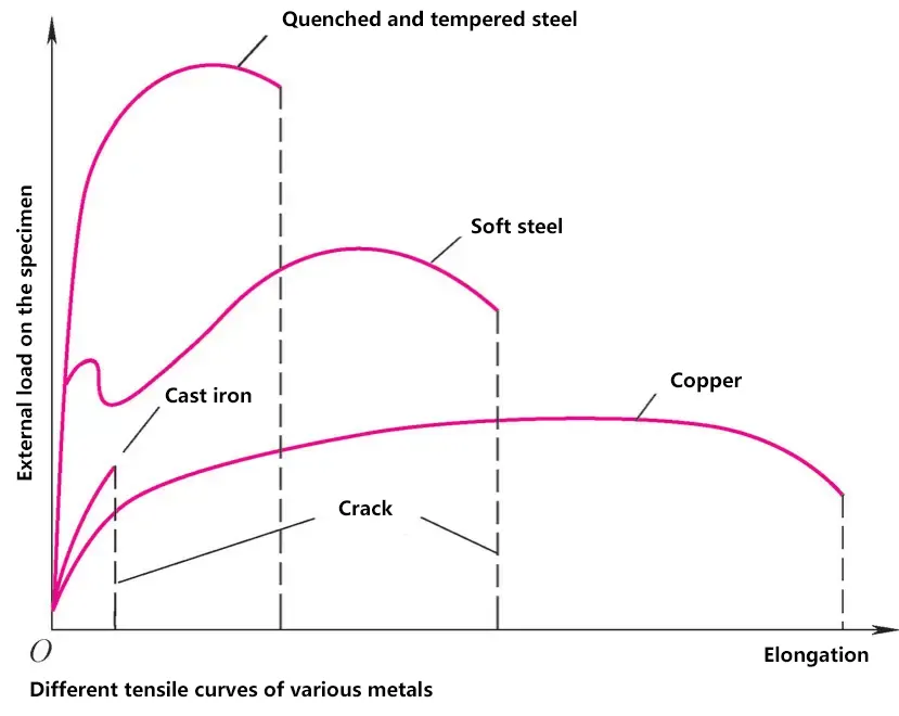
Elongation Δl = l – l0
- l – length after stretching (mm);
- l0 – original length (mm).
1) If the tensile force F doubles, the elongation Δl also doubles, and the elongation is proportional to the load. If the load is removed, the test bar returns to its original length l0 . The atomic lattice remains unchanged under stress (proportional limit P).
2) If the tensile force is increased, the material initially remains elastic, and when the external force is removed, it returns to its original length. This process continues up to the elastic limit E.
The ratio of elongation to original length is called the elongation rate: A = (l – l0 ) : l0 or A = Δl : l0 .
Due to the action of tensile stress, internal stress is generated in the material, and the force acting on a unit area is called stress.
σ=F/A0
Where
- F – applied force (N);
- A0 – original cross-sectional area (mm2 );
- σ – stress (MPa).
3) If the stress increases, the elongation rate increases significantly until the load no longer increases but the material continues to elongate. The atomic lattice begins to move, reaching the yield limit. With further loading, necking occurs in the test bar.
The elongation of the material increases greatly. This is the highest limit of the load, called the tensile limit, expressed as tensile strength Rm , which is the maximum load acting on a 1mm2 cross-section, such as Rm = 800MPa.
4) With continued loading, the material “flows” until it fractures at point Z.
5) In engineering practice, permanent deformation of workpieces or machine parts is not allowed, and loads within the elastic deformation range are permissible.
IV. Hardness Test
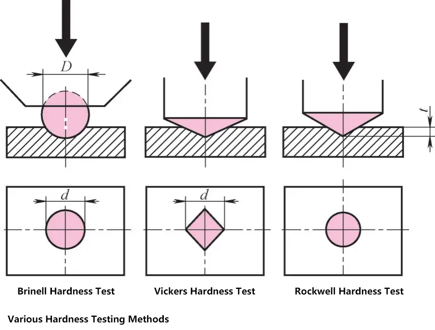
1. Brinell Hardness Test
An external force F is applied to press a steel ball with diameter D into the test material. After removing the external load, the diameter d of the indentation is measured. The Brinell hardness is
HB = External force F (N) applied to the specimen / Surface area A 0 of the indentation (mm 2 )
In actual testing, the Brinell hardness value can be directly read from the measured indentation diameter d.
2. Vickers Hardness Test
Suitable for very thin or small specimens. Measure the diagonal length of the indentation produced by a diamond pyramid on the specimen. Denoted as HV, e.g., 30HV indicates the Vickers hardness at a test load of 300N.
3. Rockwell Hardness Test
Uses a steel ball or diamond cone as the indenter, with the main measurement being the depth of penetration. To offset measurement errors due to unclean surfaces, a preload of 100N is first applied to the indenter, then the hardness gauge pointer is set to zero, followed by an additional force of 1400N.
Taking the Rockwell hardness C test method using a diamond cone as an example, if the penetration depth e = 0.2mm, then the Rockwell hardness unit HRC = 0, and for every 0.002mm difference from this penetration depth, it represents one degree of Rockwell hardness.
For example: If a cone penetrates 0.14mm into the specimen, the difference from 0.2mm is 0.06mm, so the Rockwell hardness is 0.06mm/0.002mm = 30HRC.
V. Notched Impact Test
Use dynamic load impact notch specimen. Different from the dynamic load tensile test, this method can measure the notch impact toughness.
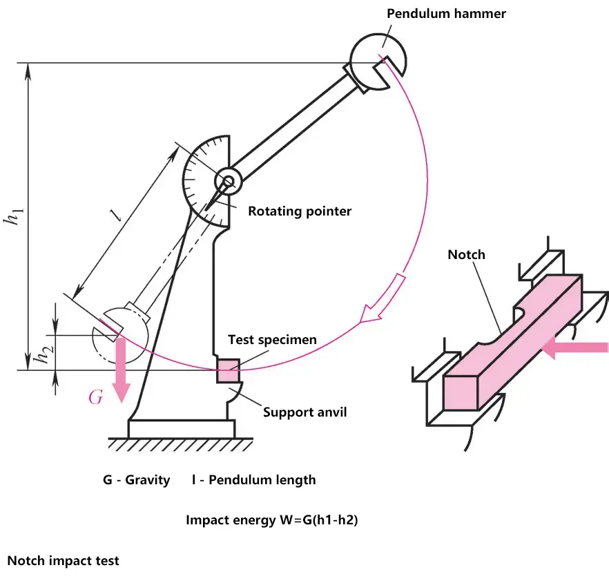
The notch impact test is performed on a pendulum impact testing machine. The pendulum hammer strikes the center of the notch of the specimen placed on the supports at both ends. After the notch fractures, the dial pointer indicates the pendulum height.
The notch impact toughness is
ak=Ak/S0
In the formula
- S 0 – Fracture cross-sectional area (cm2 );
- A k – Impact absorption energy (J).

