I. Basic Process Knowledge
1. Overview of Measuring Instruments and Measurement
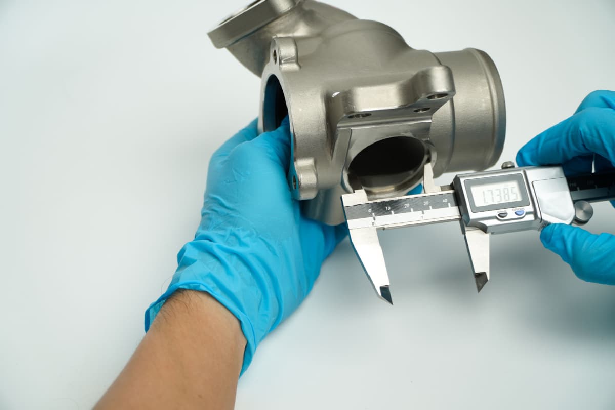
Tools used to measure the dimensions and shapes of machined surfaces are called measuring instruments. During the machining process, the dimensional accuracy and geometric precision of parts can only be controlled through measurement. Therefore, to ensure that components or products meet drawing requirements, measuring instruments must be used for measurement work.
The essence of measurement is the comparison process between a standard quantity (reference unit) and a certain measured quantity. Common measurement reference units are shown in Table 1. The commonly used imperial length unit is inch, 1 inch = 25.4mm. Other imperial length units include feet and eighths, with conversion relationships as follows:
1 foot = 12 inches
1 inch = 8 eighths
Table 1 Common Measurement Reference Units
| Common Unit Names | Unit Symbol | Comparison Reference Unit |
| Meter | m | Reference Unit |
| Decimeter | dm | 0.1m |
| Centimeter | cm | 0.01m |
| Millimeter | mm | 0.001m |
| Micron (also called mil or thou) | — | 0.00001m |
| Micrometer | μm | 0.000001m |
2. Types, Specifications, and Measurement Principles of Common Measuring Instruments
(1) Simple Measuring Instruments
1) Steel Ruler
Figure 1 shows the external view of a common steel ruler, with a minimum reading value of 1mm. Readings below 1mm can only be estimated. Steel rulers are classified by measurement length range, with common specifications including 150mm, 300mm, 500mm, and 1000mm.

2) Knife-edge Ruler
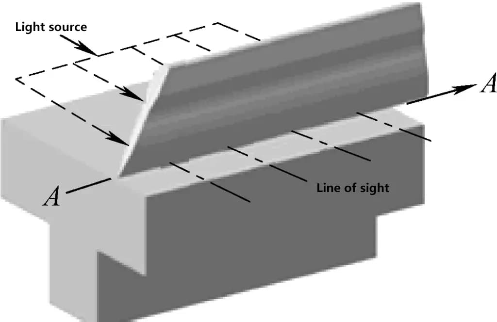
As shown in Figure 2, the knife-edge ruler is a measuring tool used to measure the straightness and flatness of workpiece surfaces. It is classified by the length of its blade edge, with common specifications including 75mm, 125mm, 175mm, etc.

As shown in Figure 3, the measurement principle of the knife-edge ruler is: gently place the blade edge of the knife-edge ruler on the surface to be measured, and judge the straightness deviation through the light transmission method. During inspection, if a uniform and faint line of light can be seen, it indicates that the workpiece surface is straight in the measured direction.
3) Try Square
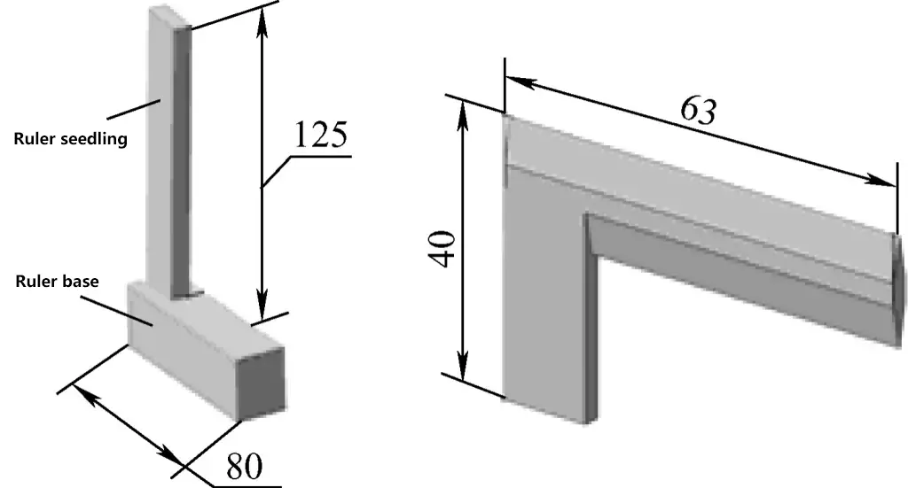
A try square is a tool used to measure the perpendicularity of internal and external surfaces of workpieces. As shown in Figure 4, common specifications include 63mm×40mm, 125mm×80mm, and a few others.
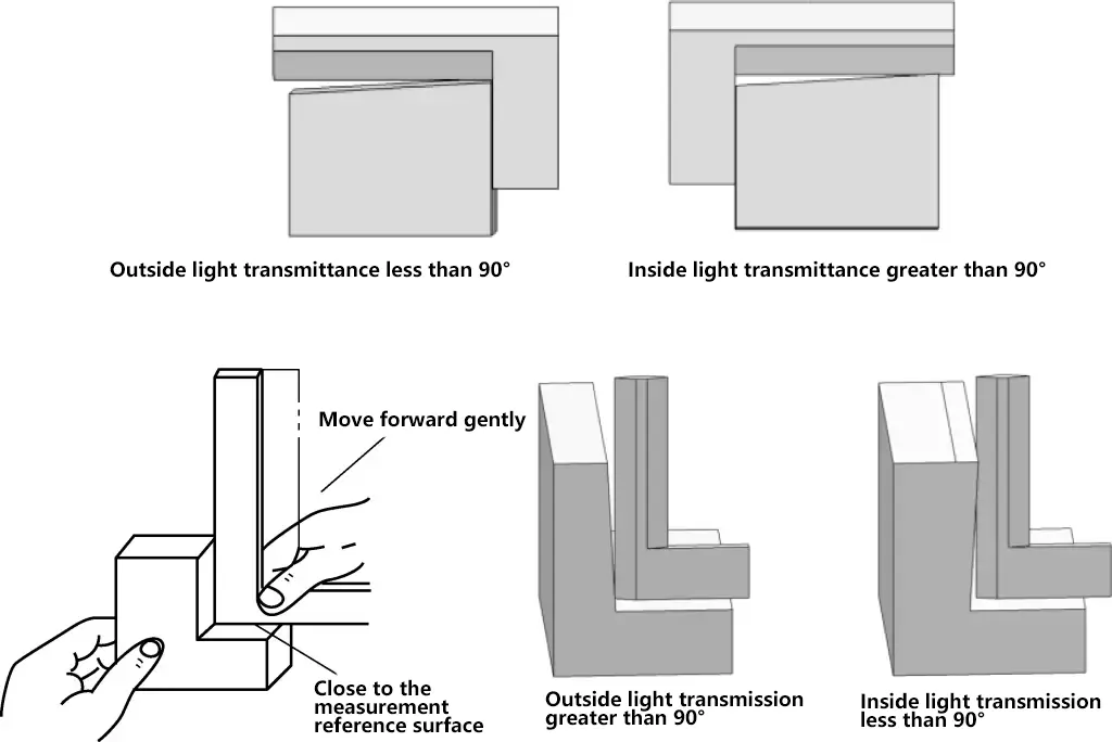
As shown in Figure 5, the measurement principle of the try square is: when measuring the perpendicularity of internal and external right angles using the light gap method, the operator should face the light source, press the base of the square firmly against the measurement reference surface, and then gently move the try square. The perpendicularity error between the measured surface and the reference surface is judged through the light transmission method.
4) Feeler gauge
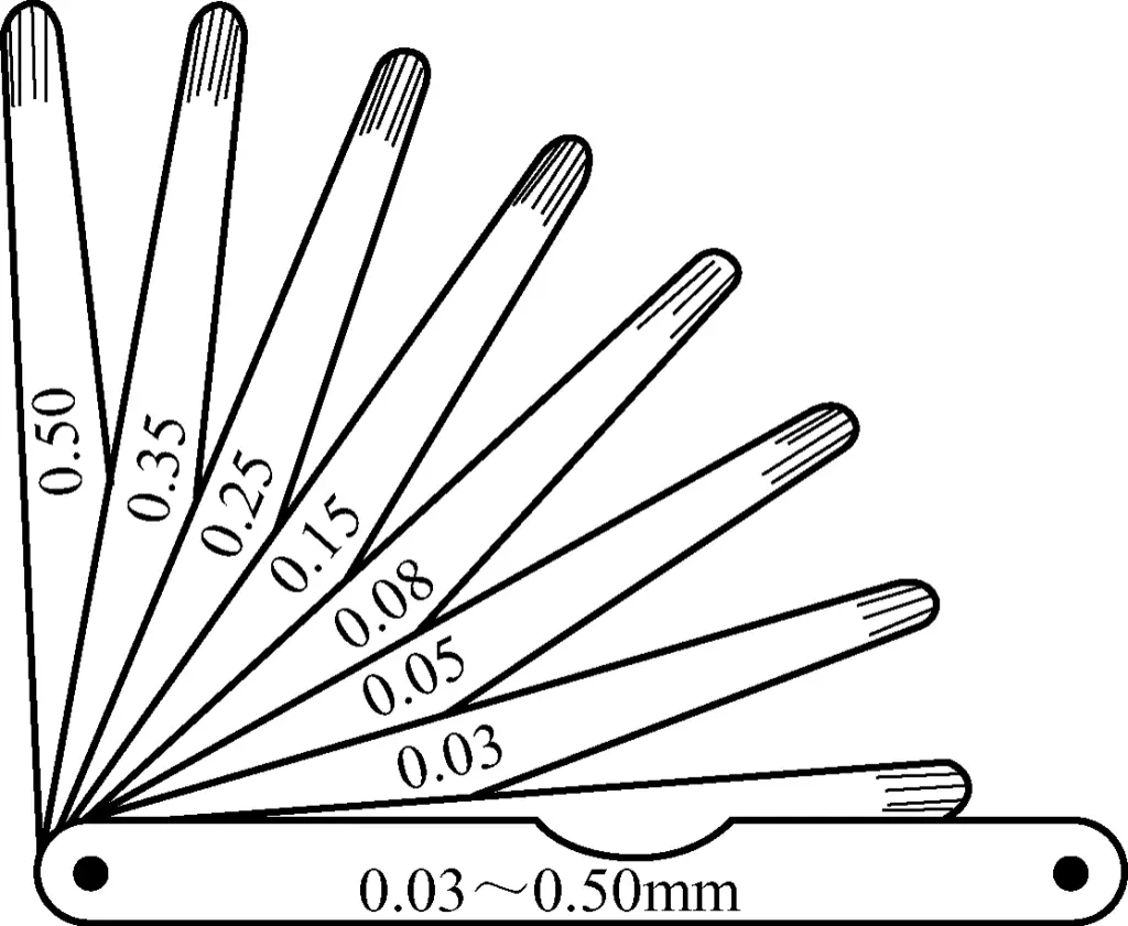
A feeler gauge consists of a set of thin steel blades of different thicknesses, often used to measure the gap between two contacting surfaces. The feeler gauge shown in Figure 6 ranges from 0.03 to 0.5mm. After initially estimating the gap size, the appropriate feeler gauge blades are combined for use.
(2) Vernier measuring instruments
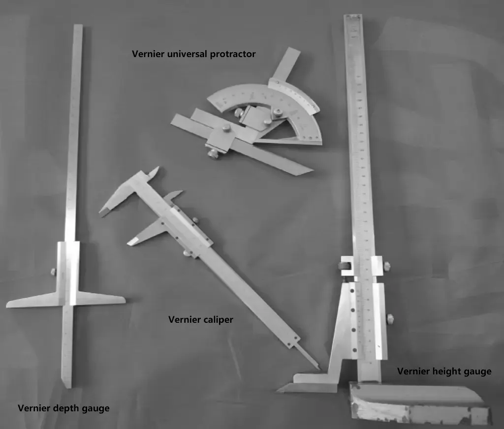
Vernier measuring instruments are medium-precision measuring tools. As shown in Figure 7, the structure, scale principle, and reading method of vernier instruments are basically the same. They usually include vernier calipers, vernier depth gauges, vernier height gauges, and vernier protractors.
1) Vernier caliper
① Types of vernier calipers
The measurement accuracy of vernier calipers can reach 0.02mm (minimum reading value is 0.02mm), and can directly measure the outer diameter, hole diameter, length, width, depth, and hole distance of workpieces. Figure 8a shows the appearance and structure of a common vernier caliper. Figure 8b shows the appearance and structure of a caliper with a fine adjustment device.
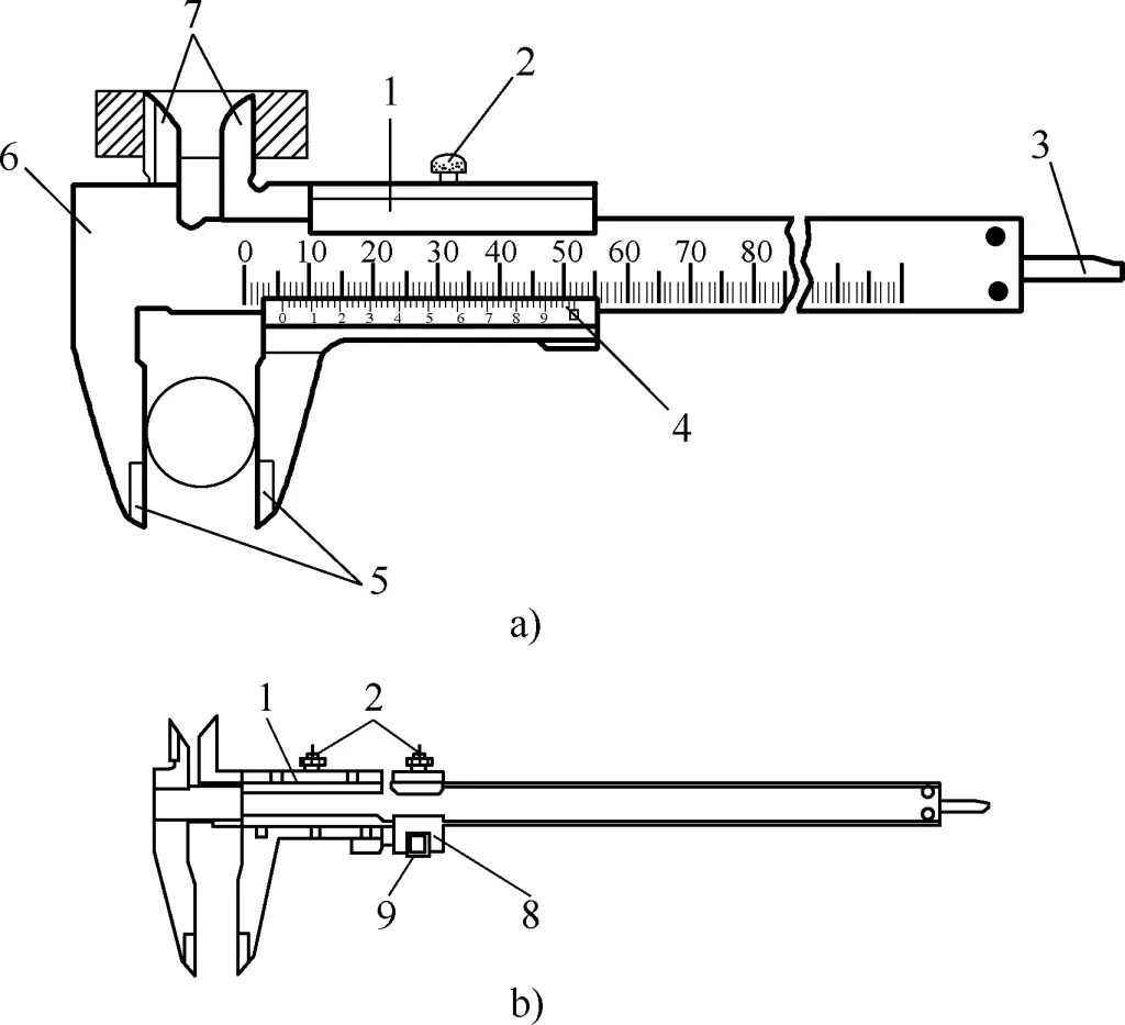
a) Appearance and structure of a common vernier caliper
b) Appearance and structure of a caliper with fine adjustment device
1—Frame
2—Locking screw
3—Depth rod
4—Vernier scale
5—Outside measuring jaws
6—Main scale
7—Inside measuring jaws
8—Fine adjustment device
9—Clearance adjustment wheel
The difference between the two: For a common vernier caliper, after loosening the locking screw on the frame, the frame drives the vernier scale to slide along the main scale. When the measuring surface of the jaws contacts the measured surface of the part, the contact pressure is controlled by the pushing force of the right hand, and the measured size is read. For a vernier caliper with a fine adjustment device, both the locking screws on the frame and the fine adjustment device need to be loosened for the frame to drive the vernier scale movement.
After the measuring surface of the jaws contacts the measured surface of the part, the locking screw on the fine adjustment device can be tightened first, then the clearance adjustment wheel on the fine adjustment device can be rotated to make the measuring jaws contact the measured surface more tightly. Finally, tighten the screw on the frame to obtain a more accurate measurement result.
② Scale principle of vernier caliper with 0.02mm precision
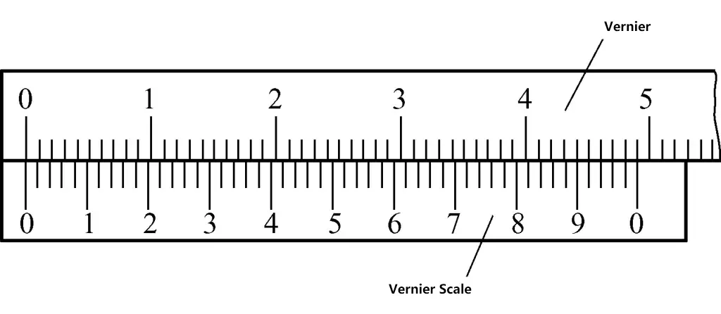
As shown in Figure 9, each small division on the main scale is 1mm. When the two jaws are combined, 50 divisions on the vernier scale exactly equal 49mm on the main scale. Thus, the interval of each division on the vernier scale = 49mm/50 = 0.98mm. The difference between each division interval on the main scale and the vernier scale is (1-0.98)mm = 0.02mm.
③ Reading method for vernier caliper with 0.02mm precision
In Figure 10, the zero line of the vernier scale is between 34 and 35mm, and the 24th division line on the vernier scale aligns with a line on the main scale. Therefore, the integer part of the measured size is 34mm, and the decimal part is 24 × 0.02mm = 0.48mm. The measured size is (34 + 0.48)mm = 34.48mm.
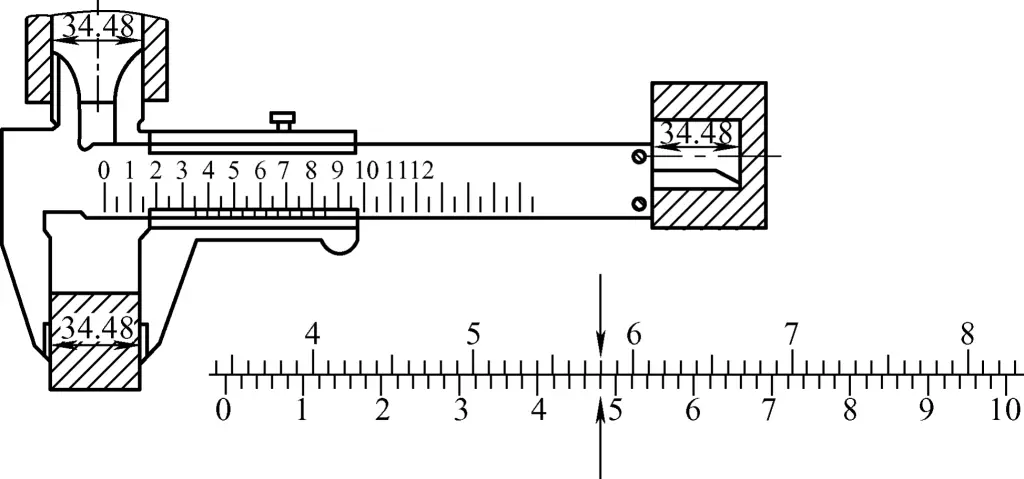
From the above, the steps for reading a vernier caliper measurement are as follows:
- Determine the integer value, which is the whole millimeter number before the zero line of the vernier scale, such as 34mm in the above example.
- By observation, judge whether the decimal value is greater than 0.5mm. If the decimal value is judged to be greater than 0.5mm, observe the aligned line after the “5” mark on the vernier scale; if the decimal value is judged to be less than 0.5mm, observe the aligned line before the “5” mark on the vernier scale. As in the above example, the 4th division after the “4” mark on the vernier scale aligns perfectly with a line on the main scale, so the decimal value is 0.48mm.
- The final measurement result is: whole millimeter value + decimal value = 34.48mm.
2) Vernier height gauge
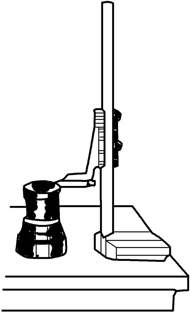
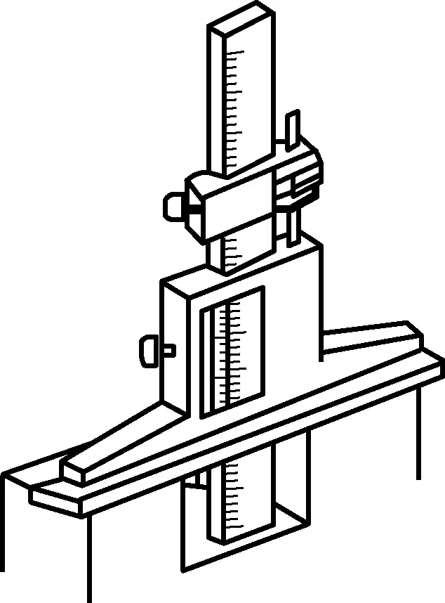
Figure 11 shows the structure of a vernier height gauge, and Figure 12 shows the use of a vernier height gauge to check the vertical dimension of a machined workpiece. According to the different measuring heights, they are usually divided into several types such as 200mm, 300mm, etc. The scale principle and reading method of the vernier height gauge are the same as those of the vernier caliper.
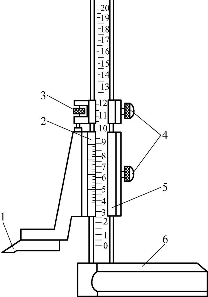
1—Measuring jaw (scriber)
2—Vernier scale
3—Fine adjustment screw
4—Locking screw
5—Frame
6—Base
3) Vernier depth gauge
As shown in Figure 13, a vernier depth gauge is used to measure the depth of machined surfaces. Its scale principle and reading method are the same as those of the vernier caliper. According to the different measuring depths, they are usually divided into several types such as 200mm, 300mm, etc. As shown in Figure 14, when measuring depth with a vernier depth gauge, its base surface should be in close contact with the machined upper surface of the workpiece.
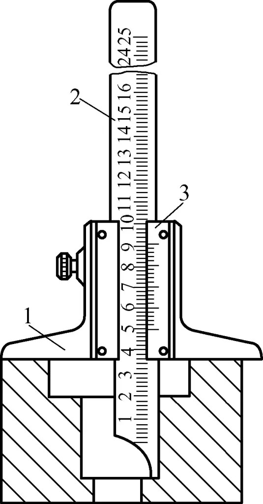
1—Base
2—Main beam
3—Vernier scale
4) Vernier protractor
The appearance and structure of a vernier protractor are shown in Figure 15. It is a type of vernier measuring instrument used to measure the internal and external angles of workpieces, with a measuring range of 0 to 320°. According to measurement accuracy, it can be divided into two types: 2′ and 5′.
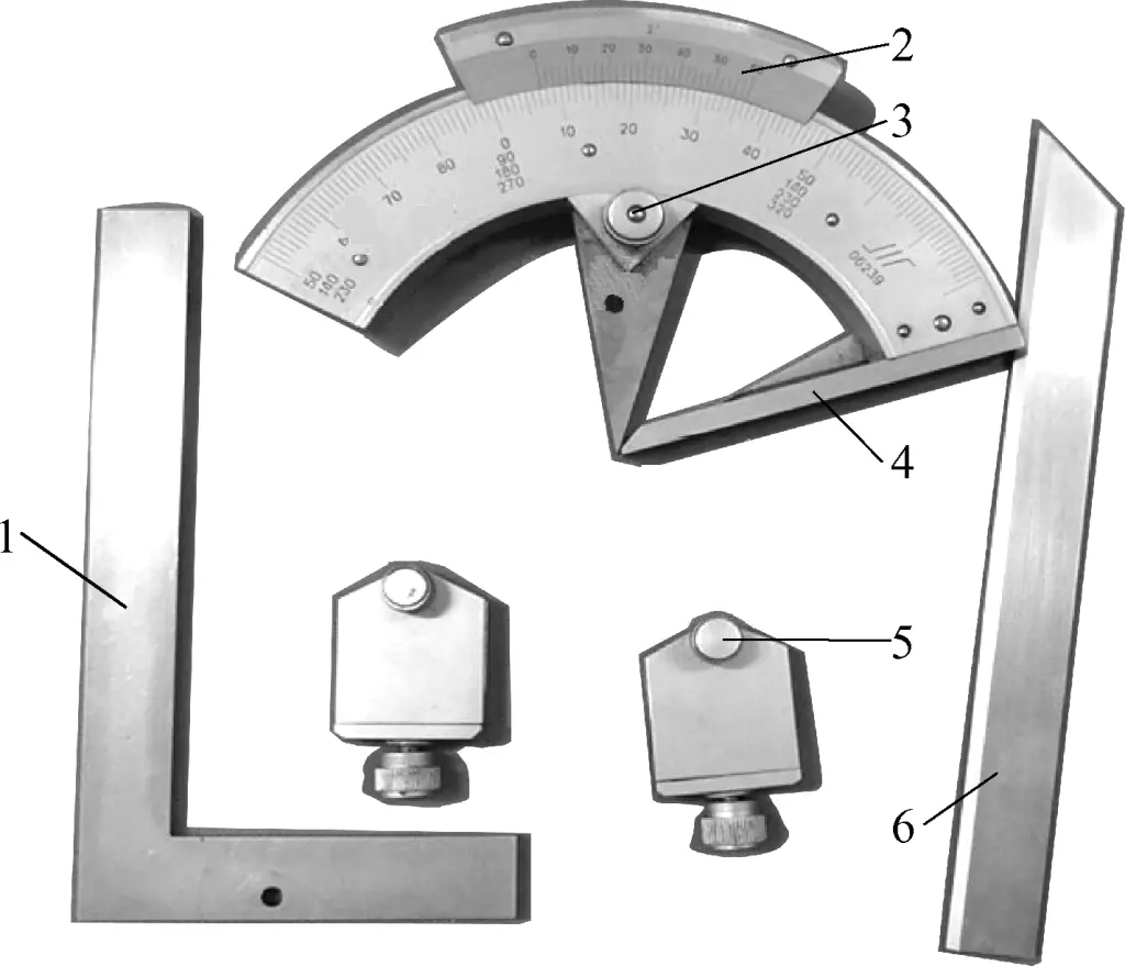
1—Protractor blade
2—Vernier scale
3—Locking screw
4—Reference edge
5—Clamp
6—Straight edge
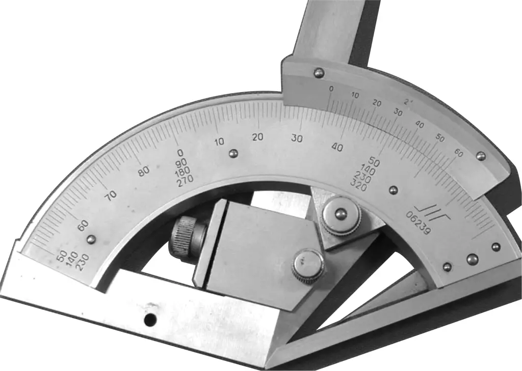
① Scale principle of vernier protractor with 2′ precision
Each division on the main scale of the vernier protractor is 1°. There are 30 divisions on the vernier scale, occupying a total angle of 29°. Therefore, the difference in degrees between each division on the two scales is
1°-29°/30=1°/30=2′
② Reading method for vernier protractor
Reading value = Whole number indicated by the zero position of the vernier scale on the main scale + Number of aligned divisions between vernier and main scale × Precision value
An actual measurement example is shown in Figure 16, with a reading value of 215°10′.
(3) Micrometer
Micrometers are precision measuring instruments that utilize the principle of screw transmission. Their measurement accuracy is 0.01mm. Types of micrometers include outside micrometers, inside micrometers, thread micrometers, etc. Although these micrometers have structural differences, their measurement principles are basically the same.
1) Structure of a micrometer
The structure of micrometers is generally similar. Commonly used outside micrometers are used to measure or inspect the outer diameter, shoulder thickness, and plate or wall thickness of parts (micrometers for measuring hole wall thickness have spherical measuring surfaces). A micrometer consists of a frame, measuring head, measuring force device, and locking device.
Figure 17 shows an outside micrometer with a measuring range of 0 to 25mm. One end of the frame 1 is fitted with a fixed anvil 2, and the other end is fitted with a measuring head. The measuring surfaces of both the fixed anvil and the spindle are inlaid with hard alloy to improve the service life of the measuring surfaces. Both sides of the frame are covered with heat insulation plates 12. When using the micrometer, hold it on the heat insulation plates to prevent body heat from affecting the measurement accuracy of the micrometer.
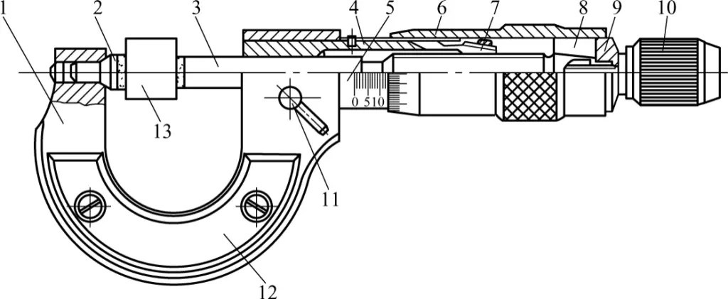
1—Frame
2—Fixed anvil
3—Spindle
4—Threaded sleeve
5—Sleeve
6—Thimble
7—Adjusting nut
8—Joint
9—Washer
10—Measuring force device
11—Locking screw
12—Heat insulation plate
13—Measured part
2) Measurement principle of micrometer
The measurement principle of a micrometer is shown in Figure 18.
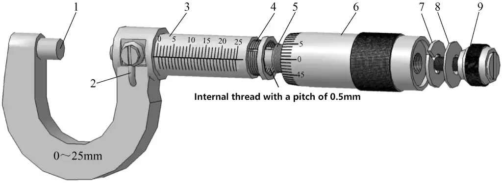
1—Fixed anvil
2—Locking screw
3—Sleeve
4—Threaded sleeve
5—Spindle (with 0.5mm pitch)
6—Thimble
7—Expansion sleeve
8—Washer
9—Clearance adjustment device
① The graduated sleeve is fixed on the threaded sleeve (with a locking screw), and the threaded sleeve is tightly integrated with the frame. Its outer cylindrical surface is graduated. Each small division above and below the center line is 1mm, and they are offset from each other by half a division.
② The thimble (movable sleeve) is connected to the spindle by a tapered hole and expansion sleeve, and its end is divided into 50 divisions. The spindle has a precision thread with a pitch of 0.5mm, which meshes with the internal thread of the threaded sleeve.
That is, when the thimble rotates one full turn, the spindle moves 0.5mm. Therefore, when the thimble rotates one division clockwise or counterclockwise, it drives the spindle to move forward or backward by a distance of 0.5mm/50 = 0.01mm. From this, it can be seen that the manufacturing accuracy of a micrometer is mainly determined by the accuracy of the spindle.
③ The rear end of the micrometer has a threaded clearance adjustment device with a ratchet structure. By turning the adjustment device, the screw meshes with the internal thread at the end of the spindle, pulling the spindle slightly to eliminate the clearance between the spindle and the internal thread of the threaded sleeve, achieving precise measurement.
The function of the locking screw is to lock the micrometer spindle after the workpiece is clamped with appropriate force, so that the measured dimension value can be read out.
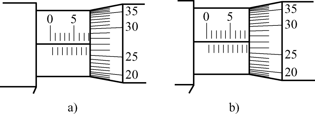
3) Reading method of micrometer
The specific reading method of micrometer can be divided into three steps:
- Read the scale size exposed on the fixed sleeve, paying attention not to miss the 0.5mm scale value that should be read.
- Read the size on the thimble, clearly see which scale line on the circumference of the thimble aligns with the center line reference of the fixed sleeve, and multiply the number of divisions by 0.01mm to get the size on the thimble.
- Add the above two numbers to get the measured size on the micrometer.
As shown in Figure 19a, the size read on the fixed sleeve is 8mm, and the size read on the thimble is 27 (divisions) × 0.01mm = 0.27mm. Adding these two numbers gives the size of the measured part, which is 8.27mm. In Figure 19b, the size read on the fixed sleeve is 8.5mm, and the size read on the thimble is 27 (divisions) × 0.01mm = 0.27mm. Adding these two numbers gives the size of the measured part, which is 8.77mm.
3. Types, specifications, and measurement principles of commonly used measuring instruments
(1) Dial indicator
The dial indicator is a high-precision measuring instrument that can only measure relative values, not absolute values. It is commonly used to check the geometric errors of workpiece surfaces and to align the relative positions between assembly parts. The reading accuracy of the dial indicator is 0.01mm. Figure 20 shows the appearance and structure of a mechanical dial indicator, and Figure 21 shows the appearance and structure of a lever dial indicator.
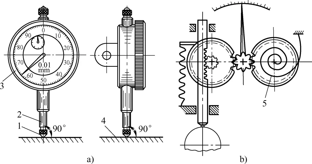
a) Appearance of mechanical dial indicator
b) Structure of mechanical dial indicator
1—Measuring tip
2—Measuring rod
3—Movable dial
4—Workpiece surface
5—Hairspring
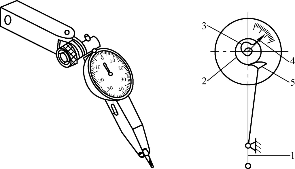
1—Lever measuring tip
2—Gear
3—Hairspring
4—Pointer
5—Sector gear
During operation, when the measuring tip of the mechanical dial indicator touches the workpiece surface, it produces an upward displacement. The gear transmission drives the pointer to rotate, thus measuring the data.
Specifically, when the measuring rod 2 moves up or down 1mm, the gear transmission system drives the large pointer to make one revolution, and the small pointer moves one division. The dial has 100 equal divisions around its circumference, with each division reading 0.01mm. Each division of the small pointer reads 1mm. The change in pointer reading during measurement is the change in dimension.
The dial can be rotated to align the large pointer with the zero line during measurement. When reading, first read the scale line passed by the small pointer (i.e., the integer part in millimeters), then read the scale line passed by the large pointer (i.e., the decimal part) and multiply by 0.01, then add the two together to get the measured value.
The difference between a lever dial indicator and a mechanical dial indicator is that when the measuring tip touches the workpiece surface, it produces a slight swing. The lever and gear cause the pointer to rotate a corresponding number of divisions, thus reading out the corresponding data. When the measuring tip swings 0.01mm, the lever and gear cause the pointer to rotate one small division, thus obtaining a reading value of 0.01mm.
(2) Spirit level
Spirit levels are mainly used to check the straightness of mechanical equipment installation surfaces, the parallelism of relative positions between parts, and the horizontal and vertical positions of equipment. Commonly used spirit levels include ordinary spirit levels and optical coincidence spirit levels.
1) Measurement principle of ordinary spirit level
① Structure of ordinary spirit level
As shown in Figure 22, ordinary spirit levels come in two types: bar-shaped and frame-shaped. It consists of a frame and a level vial. The measuring surface of the frame has a V-shaped groove to be placed on cylindrical surfaces. The level vial is an arc-shaped glass tube with scale lines on the upper outer surface. It contains ether or alcohol but is not completely filled, leaving a small bubble that always stays at the highest point of the glass tube.
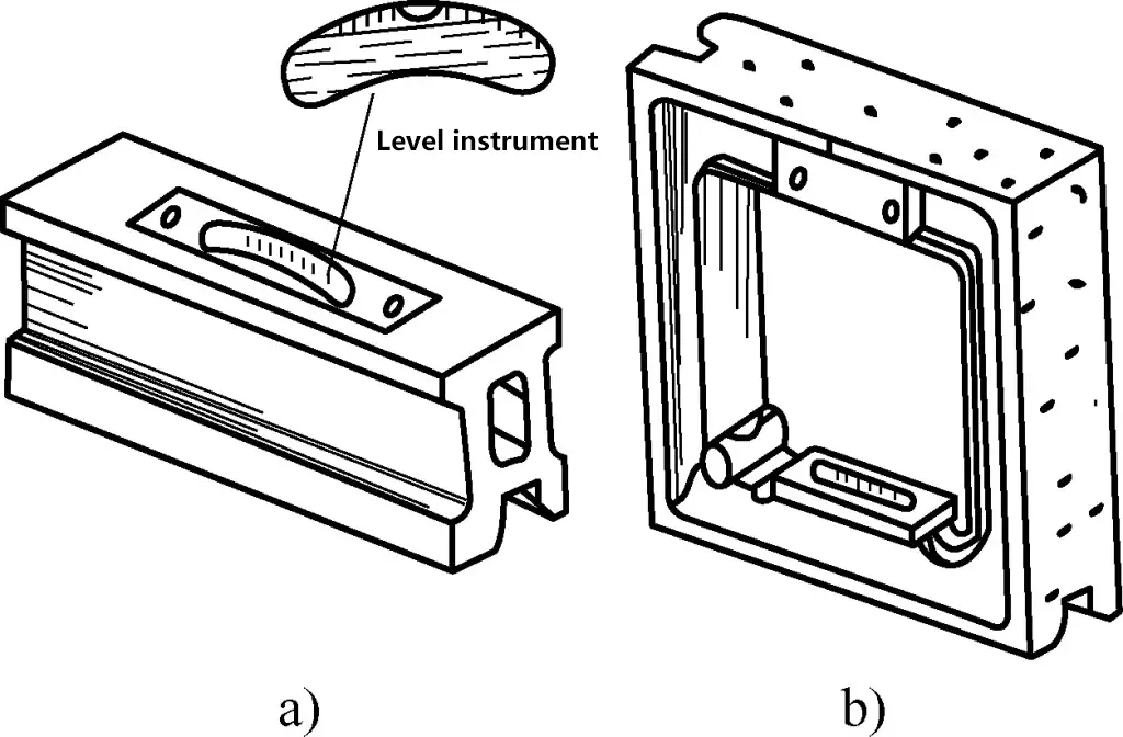
a) Bar-shaped spirit level
b) Frame-shaped spirit level
If the spirit level is in a horizontal position, the bubble will be at the center of the glass tube; if the spirit level is tilted at an angle, the bubble will move towards the higher end. The geometric error of the measured surface can be determined based on the distance the bubble moves within the glass tube.
② Scale principle of ordinary spirit level
Determining the number of divisions the bubble moves and the height difference between the two ends. Figure 23 shows the method for calculating the number of divisions the bubble moves when measuring with an ordinary spirit level. When judging, first determine the position of the two measurement baselines, then count from the left and right arc edges of the bubble. It is usually stipulated that the bubble moving to the right is positive (+) and to the left is negative (-).
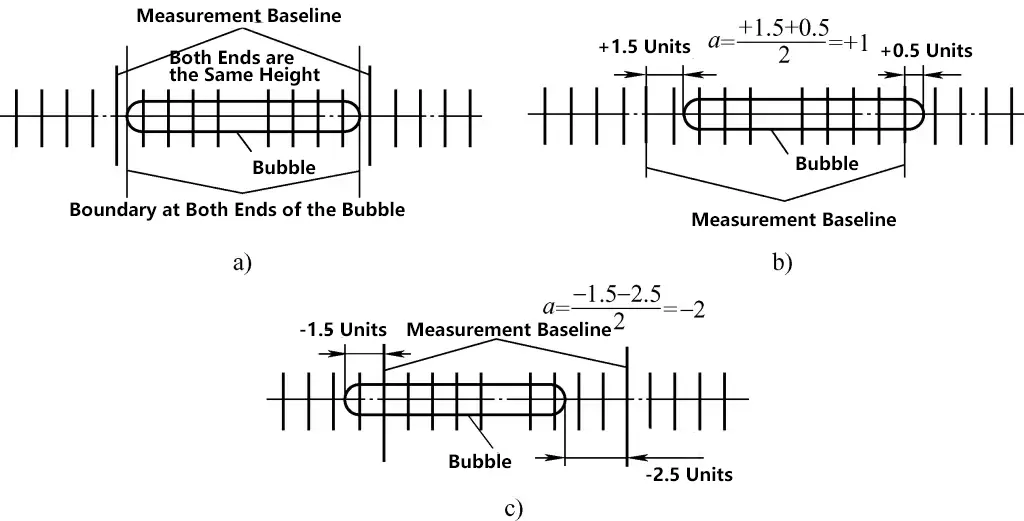
In Figure 23a, the bubble is in the middle position, indicating that both ends are at the same height; in Figure 23b, the bubble has moved 1 division to the right overall, indicating that the right end is 1 division higher than the left end; in Figure 23c, the bubble has moved 2 divisions to the left overall, indicating that the left end is 2 divisions higher than the right end.
The meaning of the reading for a spirit level with 0.02mm/m precision. Figure 24 shows a spirit level with dimensions of 200mm × 200mm and precision (scale division value or level vial division value) of 0.02mm/m. When the bubble moves one division, the bottom surface of the spirit level tilts at an angle of 4″, with a height difference of 0.02mm within 1m. Now, with the spirit level edge length of 200mm, when the bubble moves one division, the height difference h between the two ends of the spirit level can be calculated as follows:
0.02 (mm) : 1000 (mm) = h (mm) : 200 (mm)
h=0.004mm
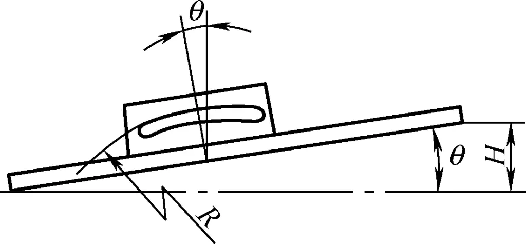
In other words, when the bubble moves one division, the height difference between the two ends of a 200mm × 200mm spirit level is 0.004mm.
2) Measurement principle of optical coincidence spirit level
Common precision spirit levels include optical coincidence spirit levels, electronic spirit levels, and inductive spirit levels, which are widely used in precision machine tool repair measurements. Their measurement accuracy can reach 0.01mm/1000m, 0.005mm/1000m, and 0.0025mm/1000m. They can accurately check the flatness, straightness of surfaces, and the accuracy of related component installation positions, while also measuring small inclination angles of workpieces.
① Structural features of optical coincidence spirit level
Figure 25 shows the structure of an optical coincidence spirit level. Compared to ordinary spirit levels, optical coincidence spirit levels have higher measurement accuracy and can obtain measurement results through absolute measurement methods (i.e., directly reading the height value at 1m).
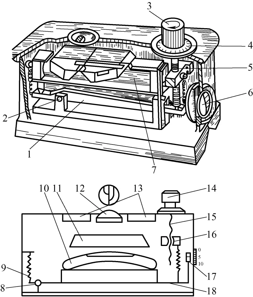
1, 18—Lever
2, 8—Lever support
3, 14—Fine adjustment knob
4—Micrometer dial (divided into 100 divisions, each division 0.01mm)
5, 15—Adjustment screw
6, 17—Side viewing window
7, 10—Level vial
9—Spring
11—Prism assembly
12—Convex lens
13—Upper window
16—Nut
The core component of the optical coincidence spirit level is the level vial. If the bottom surface (base surface) of the spirit level is not horizontal, the level vial can be adjusted to make it horizontal. The angle between the level vial and the bottom surface of the spirit level is the inclination angle (or height difference) of the measured surface. Its specific structural features are as follows:
The glass tube of the level vial is mounted on a specially made baseplate of the lever frame inside the spirit level. Its horizontal position can be adjusted by turning a knob, which operates through a screw, nut, and lever system. The screw pitch is 1mm, and the knob’s dial is divided into 100 divisions, so each division is 0.01mm, which is the scale division value of this spirit level.
The circular arcs at both ends of the bubble in the level vial’s glass tube are reflected by three prisms in different positions into the circular mirror frame in the window (which contains a convex lens), splitting the image in half. During use, if the bottom surface of the spirit level is not horizontal and there is a height difference between the ends, the images of the bubble arcs A and B will not coincide.
In this case, turning the knob for adjustment will bring the glass tube to a horizontal position, causing the images of bubble arcs A and B to coincide (i.e., forming a complete arc with half of each side arc). At this point, looking through the side viewing window, one can read the millimeter value of the height difference, and then read the number of scale divisions from the knob’s scale line (one division represents a height difference of 0.01mm over a 1m length). Adding these two values gives the height difference value.
② Measurement principle of optical coincidence spirit level
Position the spirit level with its nameplate facing your line of sight and follow these steps:
Step 1: First, adjust the spirit level itself to a horizontal state (i.e., the bottom surface of the spirit level is level with the level vial, which is equivalent to an ordinary spirit level at this point). Do this by using the fine adjustment knob to align the scale line of the slider in the side viewing window with the 5mm mark, then rotate the micrometer dial to align the “0” on the fine adjustment knob with the starting point line.
Step 2: Observe through the upper window to determine which of the non-coinciding half-arcs is higher, left or right (i.e., which half-arc is on top), as shown in Figure 25.
If the right arc is higher, turn the fine adjustment knob in the “+” direction, lowering the nut and bringing the level vial and its lever support closer to horizontal. When it reaches the horizontal state, the two half-arcs in the convex lens will form a semicircle. At this point, the lever forms an angle with the bottom surface of the spirit level (or there is a height difference at 1m). The reading is the side viewing window value (mm) plus the fine adjustment knob value (0.01mm). If this reading is greater than 5mm, the result is: reading minus 5mm, and it’s a positive value (i.e., the height above the horizontal state at 1m on the right end).
If the left arc is higher, turn the fine adjustment knob in the “-” direction, raising the nut and bringing the level vial and its lever support closer to horizontal. When it reaches the horizontal state, the two half-arcs in the convex lens will form a semicircle. At this point, the lever forms an angle with the bottom surface of the spirit level (or there is a height difference at 1m). The reading is the side viewing window value (mm) plus the fine adjustment knob value (0.01mm). If this reading is less than 5mm, the result is: reading minus 5mm, and it’s a negative value (i.e., the height below the horizontal state at 1m on the left end).
For example, if an optical coincidence spirit level with a precision of 0.01mm/m and a base length of 165mm shows a measurement result of one end being 4.08mm higher (i.e., the height at 1m), to make this spirit level horizontal, the lower end should be raised by 4.08mm × 165/1000 = 0.6732mm (which is the height difference between the two ends of the spirit level).
II. Basic operational skills
1. Usage methods and precautions for common measuring tools
(1) Usage methods for common simple measuring tools (see Table 2)
Table 2 Usage methods for common simple measuring tools

(2) Usage methods of common vernier measuring instruments
1) Usage method and precautions for vernier calipers
① Inspection of vernier calipers before use (see Figure 26)
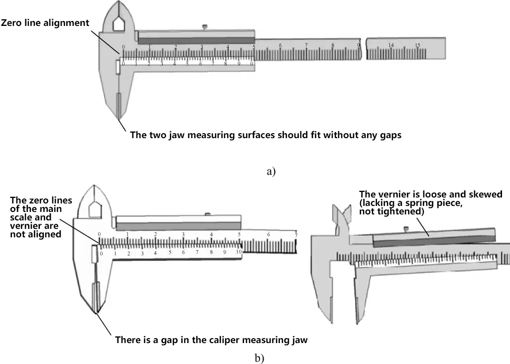
a) Calipers that meet usage requirements after inspection
b) Calipers that cannot be used after inspection
② Precautions for measuring with vernier calipers
After measuring with vernier calipers, when reading the measurement, hold the calipers horizontally towards a bright light source, keeping your line of sight as perpendicular as possible to the caliper’s scale surface to avoid reading errors caused by oblique viewing angles.
The specific usage methods for vernier calipers are shown in Figures 27 to 30.
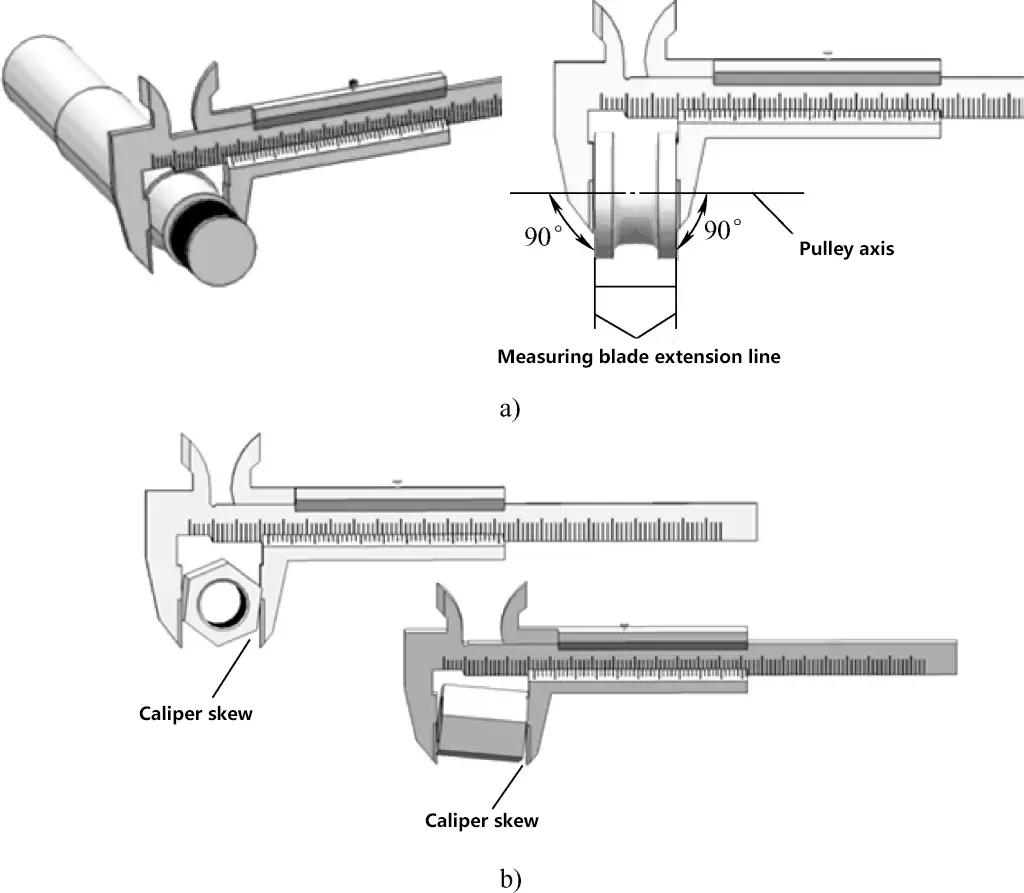

a) Correct measurement method
b) Incorrect measurement method
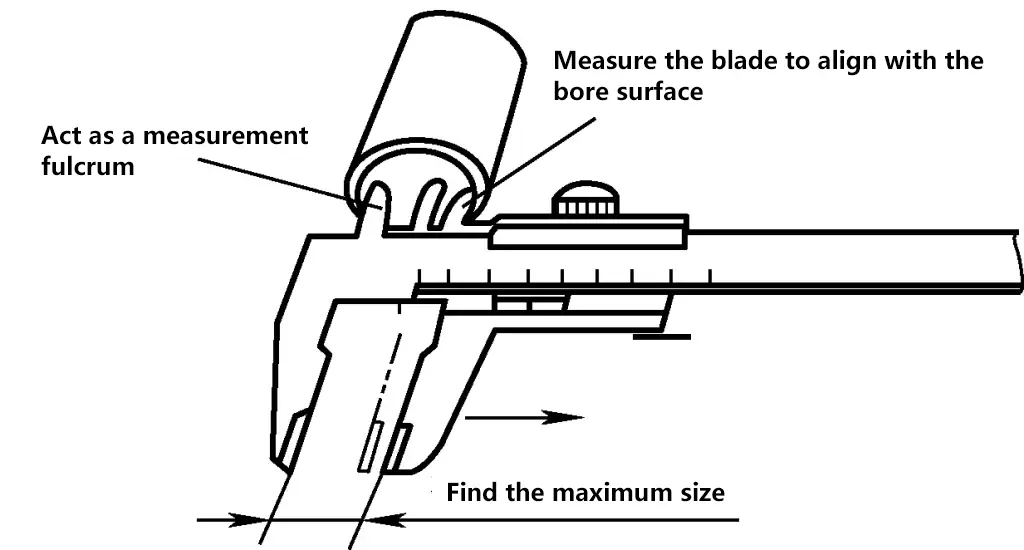
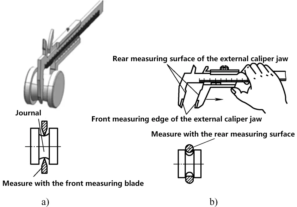
a) Correct measurement method
b) Incorrect measurement method
2) Usage method and precautions for vernier protractors
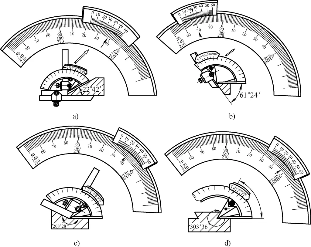
Figure 31a shows the assembly form and measurement example of a vernier protractor when measuring 0-50°. In this case, readings should be taken from the first row of the fan-shaped scale (including graduations 50, 60, 70, etc.), as in the example where the measured angle value is 22°42′.
a) Measuring 0-50°
b) Measuring 50°-140°
c) Measuring 140°-230°
d) Measuring 230°-320°
Figure 31b shows the assembly form and measurement example of a vernier protractor when measuring 50°-140°. In this case, readings should be taken from the second row of the fan-shaped scale (including graduations 140, 90), as in the example where the measured angle value is 61°24′.
Figure 31c shows the assembly form and measurement example of a vernier protractor when measuring 140°-230°. In this case, readings should be taken from the third row of the fan-shaped scale (including graduations 230, 180), as in the example where the measured angle value is 208°28′.
Figure 31d shows the assembly form and measurement example of a vernier protractor when measuring 230°-320°. In this case, readings should be taken from the fourth row of the fan-shaped scale (including graduations 270, 320), as in the example where the measured angle value is 303°36′.
Usage precautions are as follows:
- Adjust the vernier protractor to the required angle value according to processing requirements and tighten the corresponding screws.
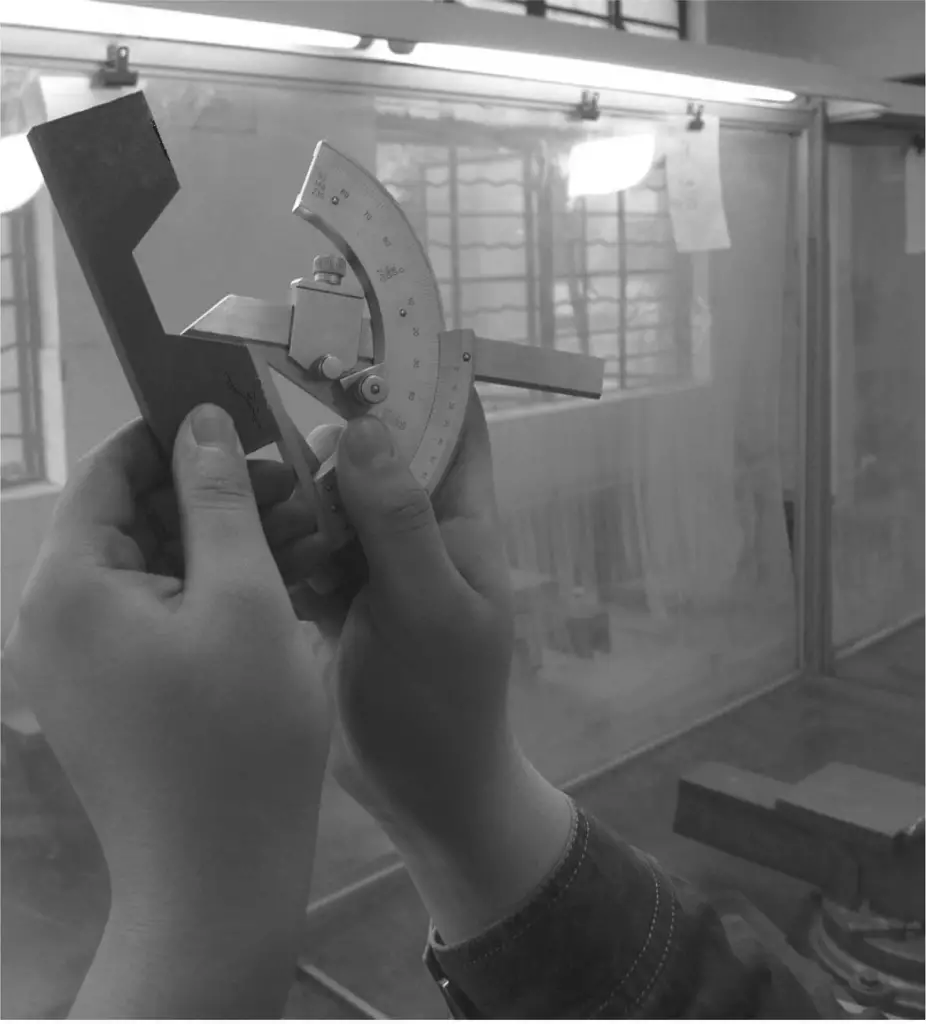
- As shown in Figure 32, place the ruler base reference edge firmly against the machined reference surface of the workpiece, and move the reference edge to measure the machined surface.
- Similar to measuring right angles, use the light transmission method to determine if the angle meets the requirements.
- During measurement, ensure that the clamping head remains securely locked, and that the straight edge, angle ruler, scale body, and vernier are all free from looseness. If any loosening or displacement occurs, recalibrate to the required standard angle and tighten the locking screws.
3) Usage method and precautions for vernier depth gauges
The usage method and precautions for vernier depth gauges are shown in Figure 33.
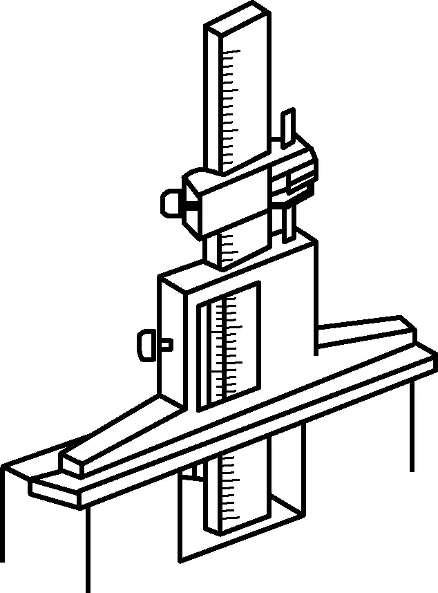
- Place the movable base firmly against the workpiece surface.
- Push the scale body down to the bottom surface being measured.
- Tighten the locking screw.
- Read the measurement value.
(3) Usage method and precautions for outside micrometers
1) Before use, clean both measuring anvil faces, rotate the ratchet stop, and bring the two anvil faces into contact (if the upper measurement limit is greater than 25mm, place a calibration rod or appropriate gauge block between the two anvil faces). There should be no gap or light leakage between the contact surfaces, and the thimble and sleeve should be aligned at the zero position.
2) When rotating the ratchet stop, the thimble should move freely and smoothly along the sleeve without any sticking or sluggishness. If there is any sluggishness, the micrometer should be sent to a metrology station for timely repair.
3) Before measuring, clean the surface to be measured on the part to avoid any dirt affecting measurement accuracy. Never use a micrometer to measure surfaces with abrasives, as this may damage the precision of the measuring faces. It is also incorrect to use a micrometer to measure parts with rough surfaces, as this can cause premature wear of the anvil faces.
4) When measuring parts with a micrometer, hold the ratchet stop cap to rotate the spindle, maintaining standard measuring pressure on the anvil faces. A “click” sound indicates appropriate pressure, and you can begin reading. Avoid measurement errors caused by improper measuring pressure.
Never forcefully rotate the thimble to increase measuring pressure, as this can cause the spindle to excessively compress the part surface, deforming the precision thread and damaging the micrometer’s accuracy. Sometimes, forcefully rotating the thimble may not severely damage the precision thread due to loose connection between the thimble and spindle, but the zero position of the micrometer will shift after the thimble slips, leading to quality incidents.
5) As shown in Figure 34, when using a micrometer to measure parts, ensure that the spindle is aligned with the direction of the dimension being measured. For example, when measuring an outside diameter, the spindle should be perpendicular to the part’s axis, not tilted. While measuring, gently rock the frame while rotating the ratchet stop to ensure good contact between the anvil faces and the part surface.
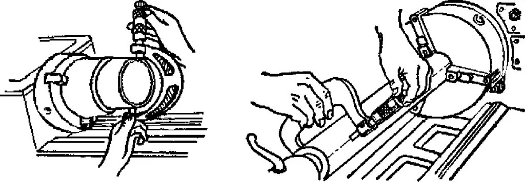
6) When measuring parts with a micrometer, it’s best to take readings while the micrometer is still on the part. After loosening, remove the micrometer to reduce wear on the anvil faces. If it’s necessary to remove the micrometer for reading, lock the spindle with the lock nut before gently sliding it off the part. It’s incorrect to use a micrometer as a snap gauge, as this not only causes premature wear of the measuring faces but can also deform the spindle or frame, compromising accuracy.
7) When reading the measurement value on a micrometer, be especially careful not to misread 0.5mm.
8) To obtain accurate measurement results, take a second measurement at the same position. Especially when measuring cylindrical parts, measure at different points around the same circumference to check for roundness errors, and at multiple positions along the length to check for cylindricity errors.
9) Do not measure workpieces at abnormal temperatures to avoid reading errors.
10) When using an outside micrometer with one hand, as shown in Figure 35a, you can pinch the movable sleeve with your thumb and index or middle finger, hook your little finger around the frame and press it towards your palm, then rotate the ratchet stop with your thumb and index finger to measure.
For two-handed measurement, follow the method shown in Figure 35b.
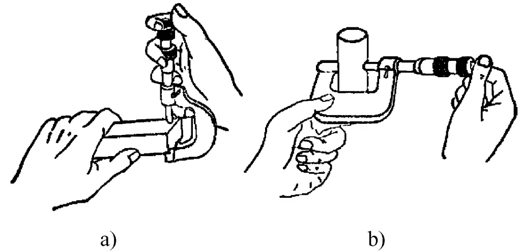
a) Single-handed use
b) Two-handed use
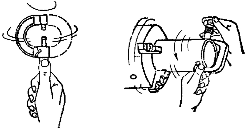
It’s worth mentioning several incorrect methods of using an outside micrometer, such as measuring a rotating workpiece, which can easily wear out the micrometer and produce inaccurate measurements. Another example is gripping the thimble and rotating it back and forth (see Figure 36) to get a quick reading, which is like striking the micrometer and can damage its internal structure.
(4) Maintenance and care of measuring instruments
To maintain the accuracy of measuring instruments and extend their service life, proper maintenance is essential. The following points should be observed:
- During use, do not store measuring instruments together with tools or cutting implements to avoid damage.
- Do not measure workpieces while the machine is running, as this will accelerate wear on the measuring instruments and may cause accidents.
- Temperature greatly affects the accuracy of measuring instruments, so they should not be placed near heat sources (electric furnaces, radiators, etc.) to avoid heat-induced deformation.
- After use, promptly clean and oil measuring instruments, then store them in their dedicated cases in a dry place to prevent rusting.
- Precision measuring instruments should undergo regular calibration and maintenance. If any abnormalities are detected in precision measuring instruments, they should be promptly verified.
2. Usage methods and precautions for common measuring devices
(1) Usage method and precautions for dial indicators
1) As shown in Figure 37, dial indicators are generally mounted on specialized stands when in use, with adjustable vertical and horizontal positions on the stand. The stand can be placed on a flat surface or attached to a relative position using a magnetic base, holding the dial indicator to measure geometric accuracy or position errors of parts.
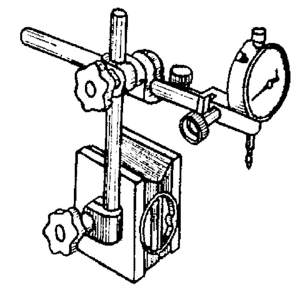
2) Before using a dial indicator for measurement, clean the measuring rod, contact point, and dial face.
3) Before use, check the smoothness of the measuring rod’s movement. When gently pushing the measuring rod, it should move smoothly within the sleeve without any sticking, and the pointer should return to its original position each time the hand is released (similar to zeroing a vernier caliper).
4) As shown in Figure 38, during measurement, the indicator base must be firmly attached, all levers must be tightened and stable; the indicator head should be as vertical as possible for measurement, and the pointer must be perpendicular to the surface being measured.
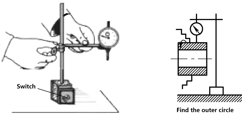
5) When using a dial indicator to measure shaft-related accuracy (such as roundness, cylindricity, shaft bend errors, etc.), the dial indicator should be positioned as shown in Figure 39. The measuring rod should be perpendicular to the axis, with its center passing through the shaft’s center.

6) To allow for negative readings during measurement, leave a compression allowance of 0.3-1mm (sometimes the small pointer is set to the middle of the range). For easier reading, before measuring, generally rotate the movable dial to set the large pointer to the zero position on the scale.
7) Do not let the indicator head suddenly hit the workpiece, and do not use the dial indicator to measure workpieces with high surface roughness values or significant unevenness.
8) During measurement, do not allow the measuring rod’s travel to exceed its measurement range, i.e., the range of the measuring rod’s up and down movement should not be too large during the measurement process.
(2) Usage method and precautions for spirit levels
1) Verification of errors in ordinary spirit levels
Due to long-term use, spirit levels can develop errors, causing inaccurate level indications by the bubble. Therefore, the accuracy of the spirit level should be verified before use.
Method 1: Place a spirit level with a reading accuracy of 0.02mm/m on a 1m long straight edge. Raise the right end by 0.02mm, and the straight edge will tilt at an angle. At this time, if the bubble in the level vial moves exactly one graduation, it indicates that the spirit level is accurate.
Method 2: Place the spirit level on a precision platform, fixing its position front, back, left, and right. Observe its graduation value, then rotate it 180° in place and place it back in the same fixed position. Observe the graduation value again. If both readings are the same and the offset direction is the same, it indicates that the spirit level has no error; otherwise, there is an error that should be noted and eliminated during measurement (the elimination method is described in the measurement of level deviation).
2) Measurement of level deviation (camber) of guide rails or mounting surfaces
① Elimination of spirit level errors
Place the spirit level directly on the guide rail. When measuring the levelness of a guide rail with a spirit level, to eliminate the spirit level’s own error, after the first measurement, turn the spirit level 180° in place and measure again. Take the average of the two graduation readings as the actual number of graduations the bubble would have shifted if the spirit level had no error.
Measuring with the spirit level placed on a straightedge. When measuring the levelness of a mounting surface using a straightedge, both the straightedge and the spirit level need to be turned together in place for measurement, taking two readings. The average of these two readings is the level deviation value of the mounting surface.
For spirit levels without errors, turning is not necessary. However, if using a straightedge, the straightedge still needs to be turned once.
② Calculation of level deviation
The levelness H, which is the actual deviation of the measured surface from level, is calculated as:
H = Actual number of graduations the bubble deviated overall × Spirit level accuracy value × Length of the measured surface
As shown in Figure 40, if measuring the longitudinal level deviation of a mounting surface using a spirit level with an accuracy value of 0.02mm/m, the mounting surface length is 3500mm, and the bubble deviates 6 graduations to the right overall, then the longitudinal level deviation value of the mounting surface is:
H=(0.02/1000)×6×3500mm=0.42mm
The calculation result indicates that the right end of the mounting surface is 0.42mm higher than the left end longitudinally.
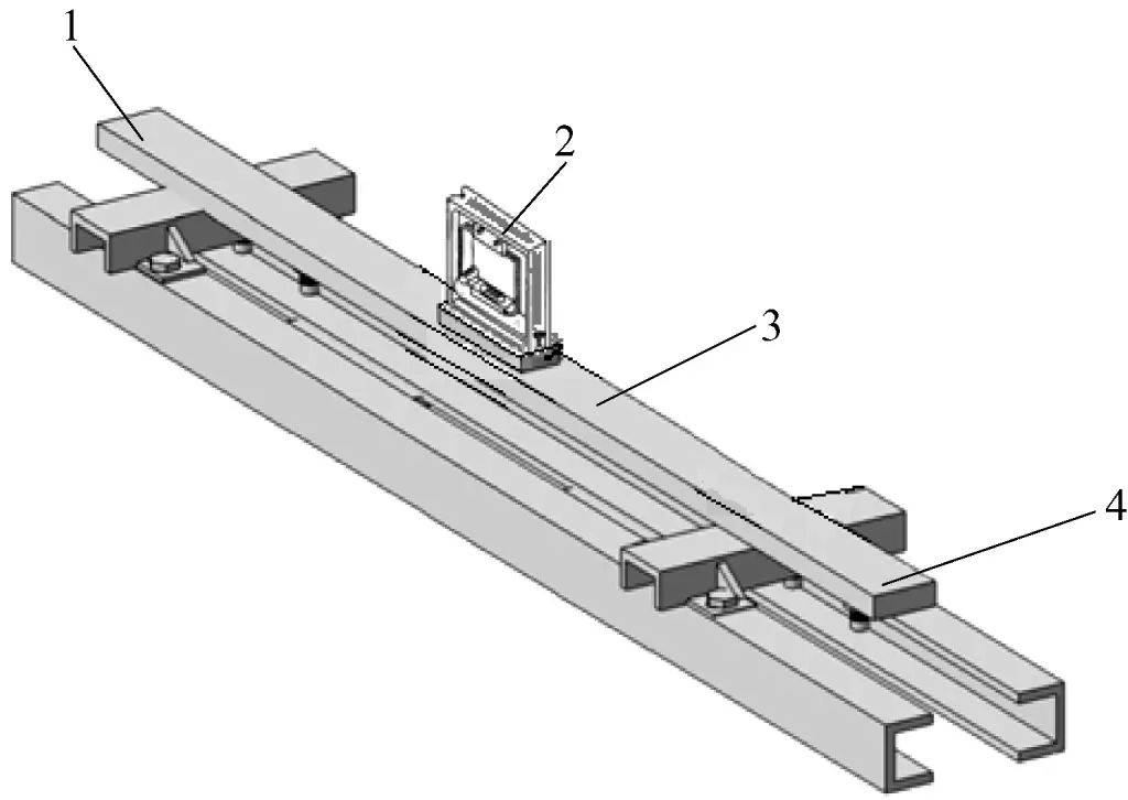
1—Longitudinal left end
2—Spirit level
3—Horizontal wooden ruler
4—Longitudinal right end
3) Measurement of guide rail straightness deviation
For example, using a box-type level with a base length of 200mm and an accuracy value of 0.02mm/1000mm to measure the straightness deviation of a guide rail with a total length of 1500mm.
Figure 41 shows an example of measurement after placing a measuring bridge plate under the level. The bridge plate is usually the same size as the level base, or slightly larger. As shown in Figure 41, the bridge plate size is 250mm.
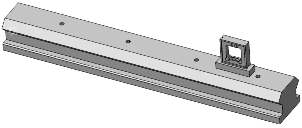
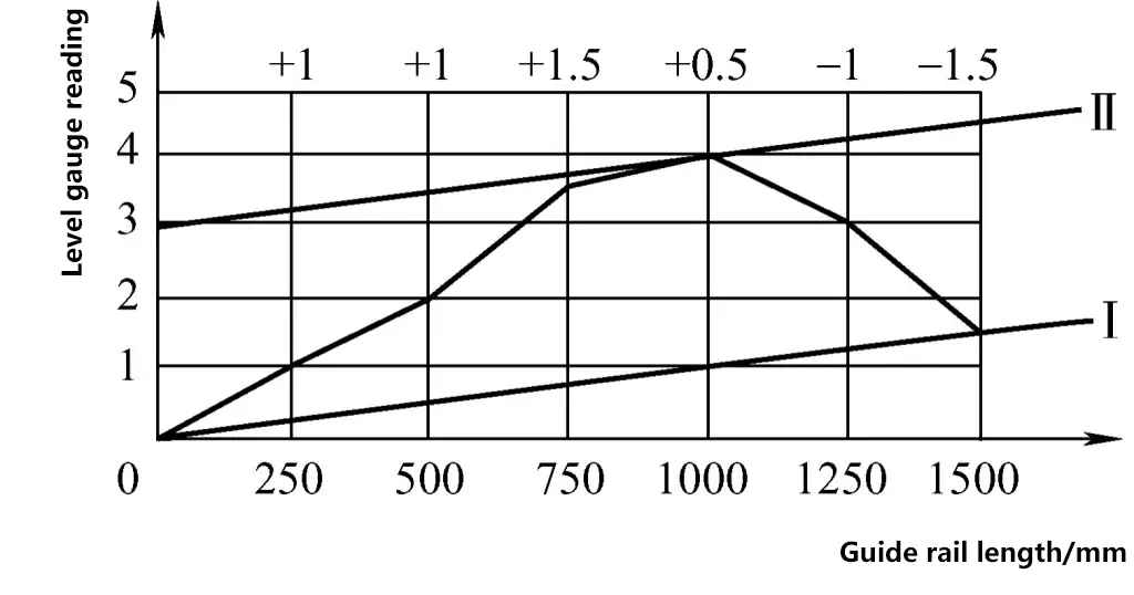
As shown in Figure 42, during measurement, first divide the surface to be measured into several equidistant sections (in this example, each section is 250mm long; without the bridge plate, each section would be 200mm long) and measure them section by section. Record the level reading for each section, then move to the next section for measurement. Ensure that each measurement position is properly connected to obtain the deviation reflecting the straightness of the guide rail surface (the continuous curve of the actual shape).
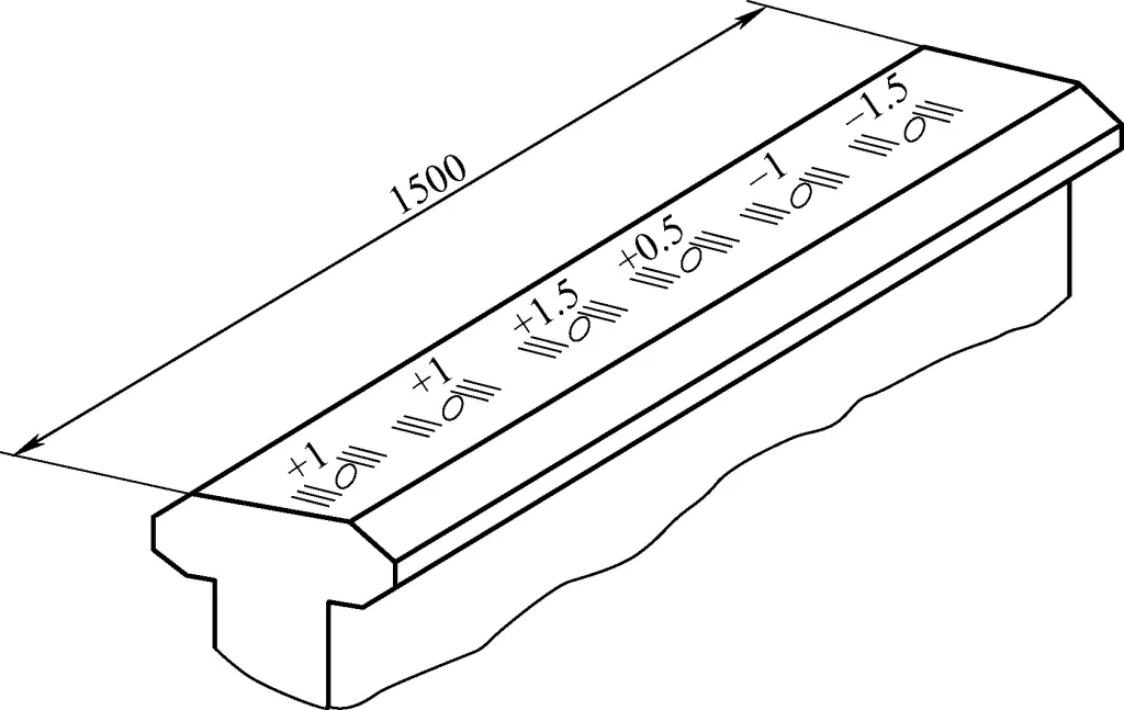
① Graphical method for measuring guide rail straightness deviation
Drawing the straightness deviation curve. Plot the measured section length and measurement values using the same scale in a rectangular coordinate system. The horizontal axis represents the measurement length of the level, and the vertical axis represents the number of divisions the level bubble has moved. Connect the intersection points to draw the guide rail straightness deviation curve, as shown in Figure 43.
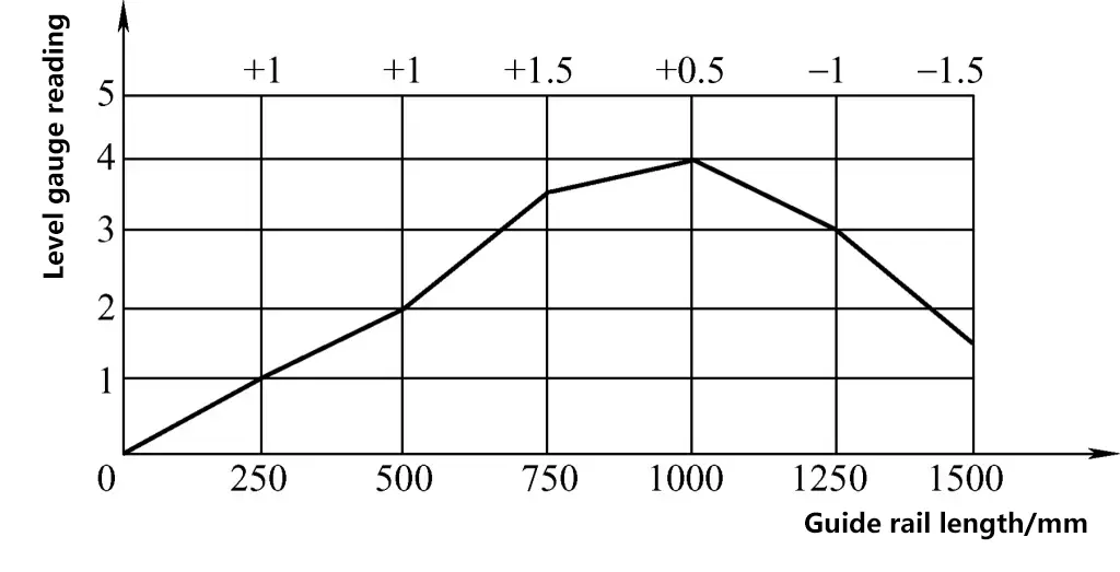
Calculation of guide rail straightness deviation. First, determine the maximum deviation in divisions. Based on the deviation curve in Figure 43, connect the end points of the curve and draw parallel lines according to the minimum envelope principle. The vertical coordinate value between the two parallel lines is the maximum deviation in divisions for the guide rail straightness. In Figure 44, the maximum deviation for the guide rail straightness is 3 divisions, and this guide rail has a convex shape in the middle.
Calculate the maximum deviation value of the guide rail straightness based on the level’s accuracy value and the measured length:
Δ=n·i·l
Where Δ is the maximum deviation value of guide rail straightness; n is the maximum deviation in divisions for guide rail straightness; i is the accuracy grade of the level; l is the length of the measured section.
The maximum deviation value of guide rail straightness in Figure 44 is
Δ=n·i·l=3×(0.02/1000)×250mm=0.015mm
② Calculation method for guide rail straightness deviation
The essence of the calculation method for guide rail straightness deviation is still based on the graphical method, using an approximate polyline to replace the actual curve of the guide rail surface. Based on geometric relationships, perform a coordinate transformation to calculate the vertical coordinate values of each vertex on the polyline relative to the line connecting the two endpoints of the guide rail. This is obtained by performing another coordinate transformation on the motion curve derived from the graphical method.
If the calculation method is used to determine the straightness deviation of the guide rail in the above example, the steps are shown in Table 3.
Table 3 Cumulative and transformed coordinates of each measurement point
| Measurement sequence | 0 (starting point) | 1 | 2 | 3 | 4 | 5 | 6 |
| Reading at each measurement point / division | 0 | +1 | +1 | +1.5 | +0.5 | -1 | -1.5 |
| Cumulative value at each measurement point / division | 0 | +1 | +2 | +3.5 | +4 | +3 | +1.5 |
| Coordinate transformation value at each measurement point (1.5/6) / division | 0 | +0.25 | +0.5 | +0.75 | +1 | +1.25 | +1.5 |
| Cumulative value – Coordinate transformation value / division | 0 | +0.75 | +1.5 | +2.75 | +3 | +1.75 | 0 |
Find the maximum absolute value from the “Cumulative value – Coordinate transformation value” in Table 3. This value is the maximum deviation in divisions for the guide rail straightness. Then substitute it into the formula to calculate the maximum straightness deviation value of the guide rail.
Δ=n·i·l=3×(0.02/1000)×250mm=0.015mm
The difference between the graphical method and the calculation method can be seen in Figure 44: in the graphical method, the start and end points are not at the horizontal position, meaning the two ends of the measured surface are not on the horizontal plane; in the calculation method, the start and end points of the drawn curve are on the horizontal plane (i.e., on the x-axis). Compared to the graphical method, it has placed the end point of the measured surface on the horizontal plane through calculation and transformation.
4) Measurement of surfaces with large horizontal deviations (calculation of feeler gauges in ordinary level measurements)
In the example of measuring the horizontal (camber) error of the installation base surface using a box-type level as shown in Figure 40, if the inclination deviation of the installation base surface is too large and the level bubble moves beyond the scale lines (since the level has only 8 divisions on each side, meaning it can only measure a height deviation from horizontal of 16×10-2mm at 1m), making normal reading impossible, the lower end should be determined first.
Then, place a feeler gauge or shim under the lower end of the level for initial adjustment. Once the level bubble returns within the readable scale range, take the reading (let this reading be A1). Finally, convert the thickness of the feeler gauge or shim into bubble divisions (let this value be A2). Add the two readings (A=A1+A2) and use the previously mentioned calculation formula to determine the height difference between the two ends of the installation surface. The specific steps are as follows:
① Determine the high and low ends
After placing the level (or with an additional base plate) on the installation base surface, use one corner as a support and slightly tilt the level. Determine the high and low ends by observing the direction of the bubble movement.
② Results after placing the feeler gauge
Assume the right side of the measured surface is higher. Place the feeler gauge under the left end of the level’s bottom surface. Two situations may occur:
First situation: The level reading still indicates that the right side is higher, suggesting that the feeler gauge thickness is less than the actual horizontal deviation of the original measured surface. In this case, the actual horizontal deviation = feeler gauge thickness + measured horizontal deviation value.
Second situation: The level reading indicates that the left side is higher, suggesting that the feeler gauge thickness is greater than the actual horizontal deviation of the original measured surface. In this case, the actual horizontal deviation = feeler gauge thickness – measured horizontal deviation value.
③ Determination of actual horizontal deviation
In the example of measuring the horizontal deviation (camber) of the installation base surface using a box-type level as shown in Figure 40, assume that after assessment, the right end of the installation base surface is higher and the left end is lower, but due to excessive inclination, the level cannot display the error in divisions. After trying with feeler gauges, it is determined that the thickness of the feeler gauge used is 0.12mm, and at this point, the level bubble moves 6 divisions to the right overall, denoted as A1.
As mentioned earlier, for a level with an accuracy of 0.02mm/m and dimensions of 200mm×200mm, each division of bubble movement represents a height difference of 0.004mm between the two ends of the level. Now, with a feeler gauge thickness of 0.12mm, the equivalent number of divisions for bubble movement A2 = 0.12mm/0.004mm per division = 30 divisions. The total accumulated divisions A is 36. Therefore, the longitudinal horizontal deviation (camber) value of the installation surface is
H=(0.02/1000)×36×3500mm=2.52mm
The calculation result shows that the right end of the longitudinal channel steel installation base surface is 2.52mm higher than the left end. After measurement, adjustments can be made by adding shims at both ends of the installed channel steel.
5) Precautions for using levels
- When using a level, movements should be stable and vibrations should be avoided; if the level needs to be slid, a strip-shaped slider should be placed under its measuring surface to prevent wear on the level’s measuring surface.
- Ensure full contact between the level’s measuring surface and the shim or measured surface. If there is rust or dirt on the measured surface, it should be removed immediately. If necessary, fine sandpaper can be used to polish the measured surface, and anti-rust measures should be taken after use.
- When observing the divisions on the level, the line of sight should be perpendicular to the level’s observation surface.
- When moving the level, it should only be lifted and placed down, not dragged, to avoid scratching the bottom surface of the level.
- Before using the level, it should be checked for any reading errors. If errors exist, necessary methods should be taken to eliminate them.
- When using the level, place it on the work surface to be measured and wait for the bubble to come to a complete stop before taking a reading.
- During measurement, if the level needs to be moved, it should only be gently lifted and placed down, ensuring it is placed correctly and flat. Do not drag the level back and forth on the surface of the equipment being measured to avoid wearing out the working surface of the level. When checking the vertical surface of equipment, apply even pressure to hold it firmly against the vertical surface of the equipment.
- When bringing the level from a low-temperature environment to a high-temperature environment, do not use it immediately. Also, do not use it under strong artificial light or direct sunlight. After use, wipe it clean with a clean cloth and apply a layer of anti-rust oil on the working surface before storing it carefully in its case.

