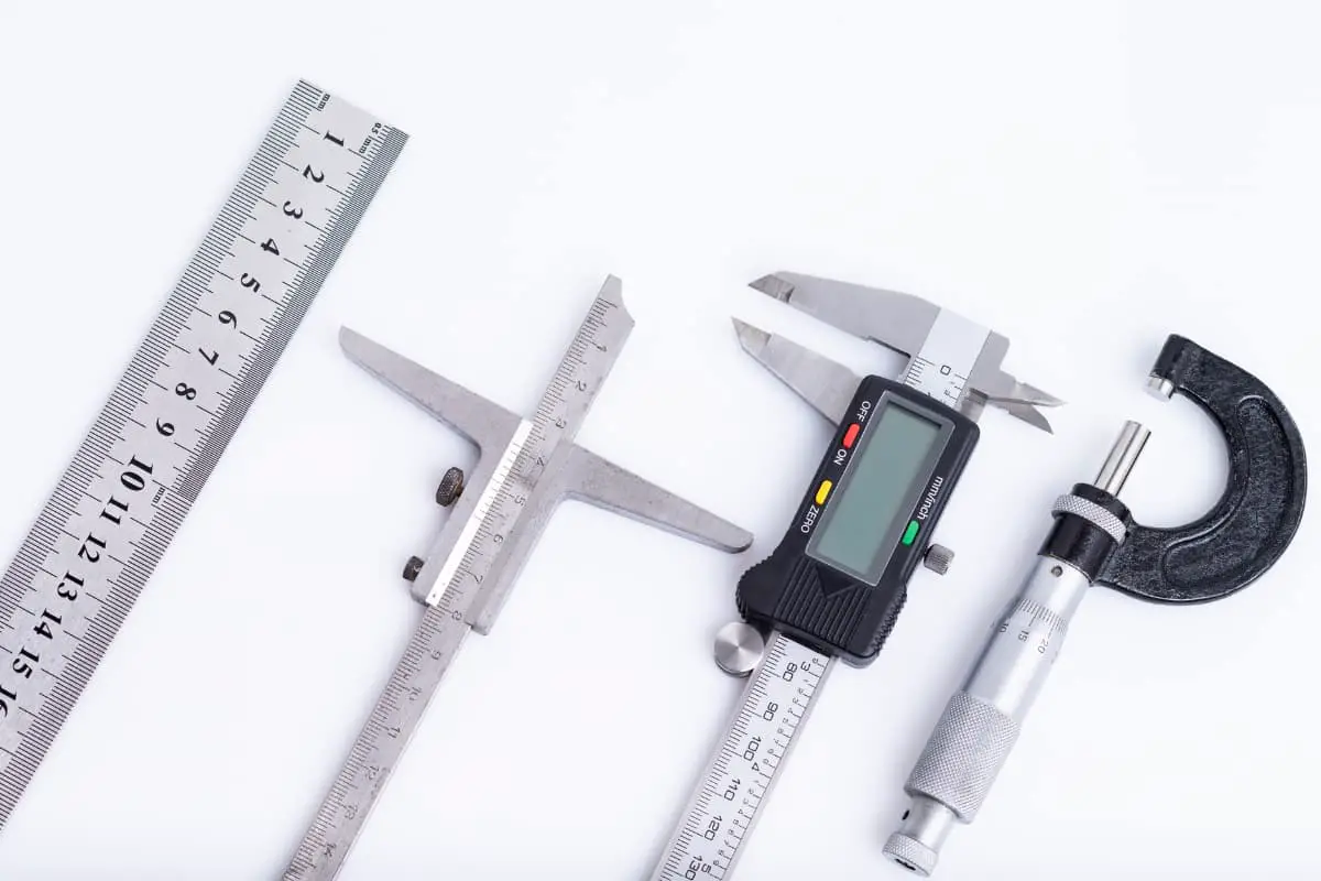
I. Calipers
Calipers are widely used general-purpose measuring instruments with features such as simple structure, ease of use, and large measuring range. They are used to measure the inner diameter, outer diameter, width, thickness, hole spacing, height, and depth of workpieces. Commonly used types include vernier calipers, digital calipers, and dial calipers.
1. Use and precautions for vernier calipers
Common vernier calipers are shown in Figure 1.
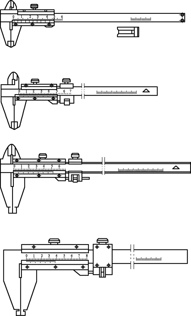
1) Before use, observe whether the zero line and end line of the vernier scale align with the corresponding lines on the main scale, and adjust if necessary. For errors that cannot be adjusted, make corresponding error corrections during measurement.
2) When measuring, position with the fixed jaw and move the sliding jaw to find the correct position for reading. The two jaws should not be tilted during measurement.
3) For calipers with a depth rod, position the end face of the main scale, then push the slider to make the measuring surface of the depth rod contact the surface being measured. Ensure that the depth rod is aligned with the direction of the dimension being measured and not tilted in any direction.
4) As vernier calipers have no measuring force device, control the measuring force carefully. For calipers with fine adjustment devices, tighten the fixing screw on the fine adjustment device before turning the fine adjustment nut. Over-adjustment or under-adjustment of the jaws can easily cause errors in measurements.
5) Use knife-edge outer jaws to measure the outer diameter of bent tubes and the diameter of arc-shaped tool grooves.
6) When using double-sided vernier calipers to measure internal dimensions, add the actual size of the inner jaws to the reading on the vernier caliper to get the internal dimension of the workpiece being measured.
2. Use and precautions for digital calipers
Digital calipers are shown in Figure 2.

1) Do not disassemble the digital scale, drop it, or apply excessive external force.
2) Do not press the buttons with sharp objects, as this will affect button sensitivity.
3) Do not use or store the digital scale in direct sunlight or in excessively cold or hot environments.
4) Do not use the digital scale in environments with high voltage or strong magnetic fields.
5) Do not apply voltage to digital measuring instruments to avoid damaging the circuit.
6) Before measuring, wipe the measuring surfaces with a soft cloth, press the “zero” button to set the zero position, then proceed with measurement.
7) To reduce measurement errors, the force used during measurement should be as close as possible to the force used when calibrating the zero position.
8) When measuring, position with the fixed jaw and move the sliding jaw to find the correct position for reading. The two jaws should not be tilted during measurement.
9) For calipers with a depth rod, position the end face of the main scale, then push the slider to make the measuring surface of the depth rod contact the surface being measured. Ensure that the depth rod is aligned with the direction of the dimension being measured and not tilted in any direction.
10) Remove the battery when not in use for extended periods.
3. Use and precautions for dial calipers
Dial calipers are shown in Figure 3.

1) Do not disassemble dial calipers, drop them, or apply excessive external force.
2) Do not use dial calipers in environments with strong magnetic fields.
3) Before measuring, check the correctness of the dial and pointer, ensuring there is no looseness, and check the smoothness and stability of the pointer’s rotation.
4) When measuring, position with the fixed jaw and move the sliding jaw to find the correct position for reading. The two jaws should not be tilted during measurement.
5) For calipers with a depth rod, position the end face of the main scale, then push the slider to make the measuring surface of the depth rod contact the surface being measured. Ensure that the depth rod is aligned with the direction of the dimension being measured and not tilted in any direction.
II. Micrometers
Micrometers are precise measuring instruments that should be handled with care and gentle movements to avoid impact.
The threads inside the micrometer are very precise. When using, note: Before measuring, turn the micrometer’s measuring force device to bring the two measuring faces together, and check if the zero line on the thimble aligns with the fixed sleeve. If there is an error, adjust the fixed sleeve to zero.
When measuring, turn the measuring force device by hand. Do not apply excessive force when turning the thimble and measuring force device. When turning the thimble to bring the spindle close to the object being measured, always switch to turning the measuring force device instead of turning the thimble to press the spindle against the object.
Never forcibly turn the thimble when the measuring faces have gripped the object being measured or when the locking device is tightened. Some micrometers have insulation devices on the frame to prevent small errors caused by hand temperature causing frame expansion.
When using, hold the insulation device and minimize contact with the metal parts of the frame. When using a micrometer to measure the same dimension, generally repeat the measurement several times and take the average as the measurement result. After use, clean the micrometer with gauze, leave a small gap between the anvil and spindle, and place it in its case.
If not used for a long time, apply grease or lubricating oil and store in a dry place. Avoid contact with corrosive gases. Micrometers can be classified by purpose and structure into: outside micrometers, inside micrometers, depth micrometers, thread micrometers, tube micrometers, etc.
1. Use and precautions for outside micrometers
Outside micrometers are shown in Figure 4.
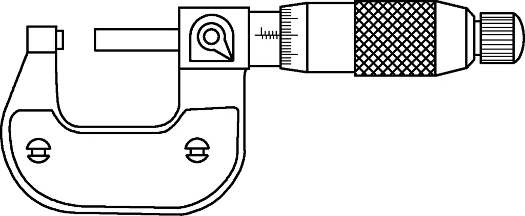
1) Choose the appropriate size of outside micrometer based on the workpiece being measured. The thimble should move smoothly throughout the entire measuring range.
2) Clean the measuring surfaces of the outside micrometer’s reference block.
3) Before measuring, repeatedly calibrate the zero position of the outside micrometer. Also check the standard zero position frequently during use to ensure measurement accuracy.
4) When measuring, ensure the measured part of the workpiece is clean, and that the measuring faces of the outside micrometer correctly contact the workpiece at the diameter.
5) After measuring, promptly clean the frame and measuring faces, and place in a dedicated case. Store in designated areas according to storage requirements, and do not mix with cutting tools or other tools.
6) If any abnormalities occur during use, promptly send the outside micrometer to the relevant department for repair.
2. Use and precautions for inside micrometers
Inside micrometers and three-point inside micrometers are shown in Figure 5.
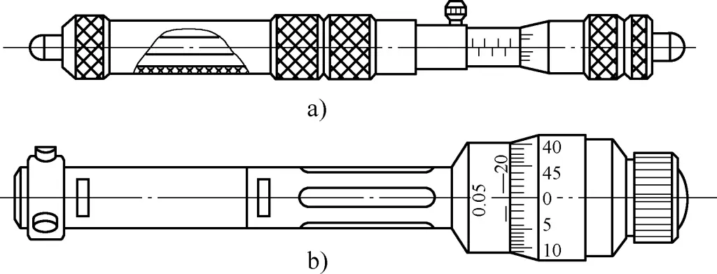
a) Inside micrometer
b) Three-point inside micrometer
1) Choose the appropriate size of inside micrometer based on the workpiece being measured. The thimble should move smoothly throughout the entire measuring range.
2) Clean the measuring surfaces of the inside micrometer’s reference block.
3) Before measuring, repeatedly calibrate the zero position of the inside micrometer. Also check the standard zero position frequently during use to ensure measurement accuracy.
4) When measuring, ensure the measured part of the workpiece is clean, and that the measuring faces of the inside micrometer correctly contact the workpiece at the maximum diameter in the radial direction and the minimum in the axial direction (actual size of the hole).
5) After measuring, promptly clean the frame and measuring faces, and place in a dedicated case. Store in designated areas according to storage requirements, and do not mix with cutting tools or other tools.
6) If any abnormalities occur during use, promptly send the inside micrometer to the relevant department for repair.
3. Use and precautions for depth micrometers
Depth micrometers are shown in Figure 6.
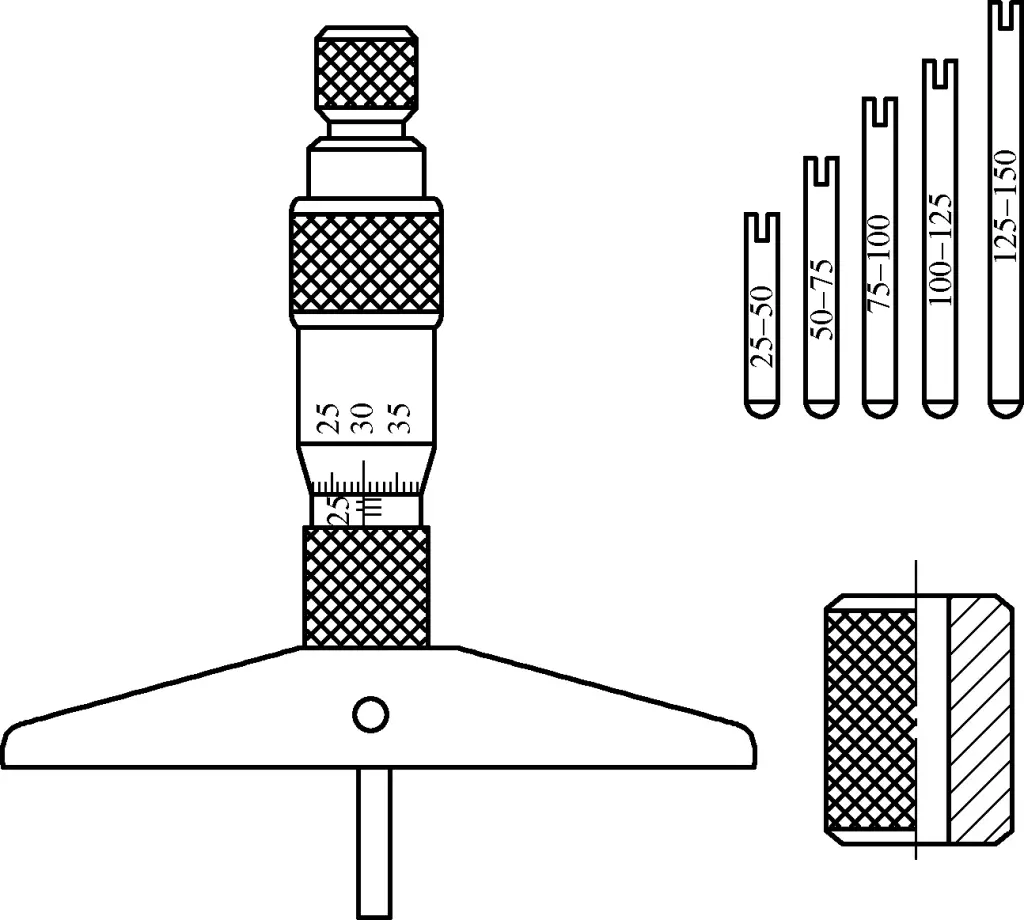
1) Choose the appropriate size of depth micrometer based on the workpiece being measured. The thimble should move smoothly throughout the entire measuring range.
2) Clean the measuring surfaces of the depth micrometer’s reference block.
3) Before measuring, repeatedly calibrate the zero position of the depth micrometer. Also check the standard zero position frequently during use to ensure measurement accuracy.
4) When measuring, ensure the measured part of the workpiece is clean, and that the measuring rod of the depth micrometer is parallel to the direction of the depth being measured.
5) After measuring, promptly clean the frame and measuring faces, and place in a dedicated case. Store in designated areas according to storage requirements, and do not mix with cutting tools or other tools.
6) If any abnormalities occur during use, promptly send the depth micrometer to the relevant department for repair.
4. Use and precautions for thread micrometers
Thread micrometers are shown in Figure 7.
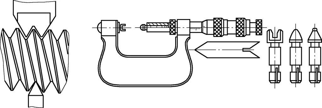
1) Choose the appropriate size of thread micrometer and measuring head specification based on the pitch diameter, thread pitch, and tooth profile of the workpiece being measured. The thimble should move smoothly throughout the entire measuring range.
2) Clean the measuring surfaces of the thread micrometer’s reference block.
3) Before measuring, repeatedly check the accuracy of the thread micrometer’s zero position. Frequently check the standard zero position during use to ensure measurement accuracy.
4) When measuring, ensure the measured thread profile on the workpiece is clean and free of burrs, and that both measuring heads of the thread micrometer correctly contact the sides of the workpiece’s thread.
5) After measuring, promptly clean the frame and measuring faces, and place in a dedicated case. Store in designated areas according to storage requirements, and do not mix with cutting tools or other tools.
6) If any abnormalities occur during use, promptly send the thread micrometer to the relevant department for repair.
5. Use and precautions for tube micrometers
Tube micrometers are shown in Figure 8.
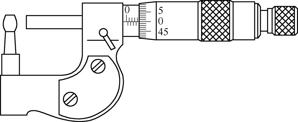
1) Choose the appropriate size of tube micrometer based on the workpiece being measured. The thimble should move smoothly throughout the entire measuring range.
2) The measuring surface of the wall thickness micrometer’s calibration block should be cleaned.
3) Before measurement, repeatedly calibrate the accuracy of the wall thickness micrometer’s zero position. During use, frequently check the standard zero position to ensure measurement accuracy.
4) When measuring, ensure the measured part of the workpiece is clean. Make sure the two measuring surfaces of the wall thickness micrometer are parallel to the measured surface of the workpiece. Generally, measure the thickness at three points to check parallelism.
5) After measurement, promptly clean the micrometer body and measuring surfaces, place it in a dedicated box, and store it in the designated area according to storage requirements. Do not mix it with cutting tools or other tools.
6) If any abnormalities occur during use, the wall thickness micrometer should be promptly sent to the relevant department for repair.
III. Dial Indicator
A dial indicator is a precision measuring instrument with an indicator dial, featuring simple structure, ease of use, and low cost. It is mainly used for relative measurement of length and relative measurement of shape and position deviations. It can also be used for positioning and indication in some machine tools or measuring devices. Common dial indicators include clock-type dial indicators and lever-type dial indicators.
1. Use and precautions for clock-type dial indicators
The clock-type dial indicator is shown in Figure 9.
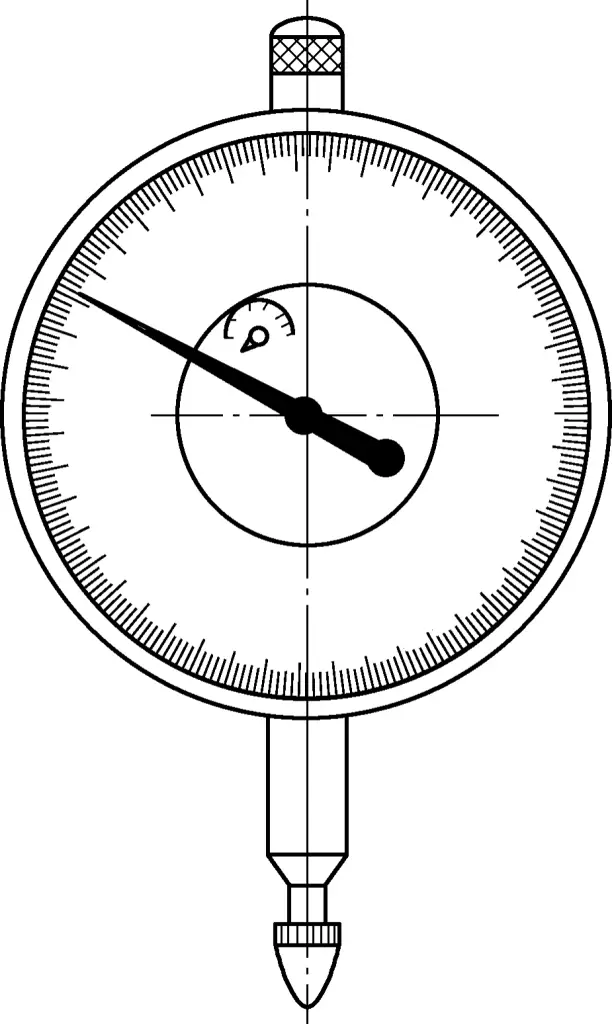
1) Choose dial indicators with different strokes according to the workpiece to be measured.
2) Before measurement, check for any looseness in the dial and pointer, and examine the smoothness and stability of the pointer rotation.
3) During measurement, the measuring rod should be perpendicular to the workpiece surface. When measuring a cylinder, the measuring rod should be aligned with the cylinder’s centerline. When the measuring head contacts the workpiece surface, the measuring rod should have a pre-compression of 0.3 to 1mm to maintain a certain initial measuring force, preventing negative deviations from going undetected.
4) After measurement, promptly clean the indicator body and measuring rod, place it in a dedicated box. Store it in the designated area according to storage requirements, and do not mix it with cutting tools or other tools.
5) If any abnormalities occur during use, the dial indicator should be promptly sent to the relevant department for repair.
2. Use and precautions for lever-type dial indicators
The lever-type dial indicator is shown in Figure 10.
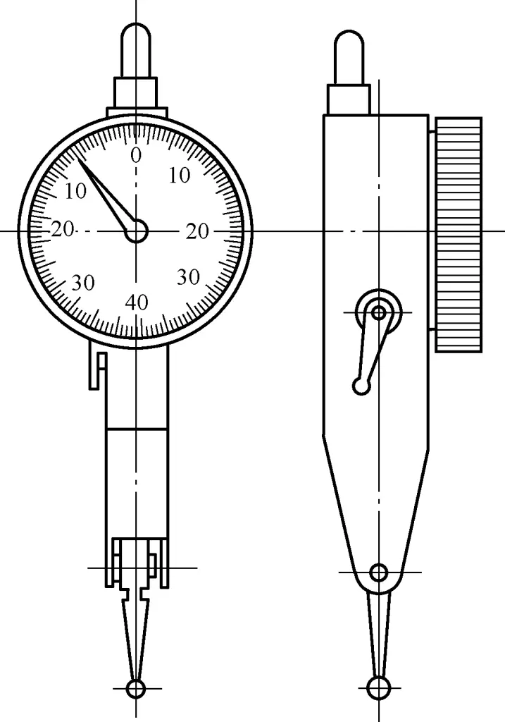
1) Before measurement, check for any looseness in the dial and pointer, and examine the smoothness and stability of the pointer rotation.
2) According to the measurement needs of the workpiece, the lever measuring head can be moved to change the measurement direction.
3) During measurement, the axis of the measuring rod should be parallel to the surface of the measured workpiece. The smaller the angle, the smaller the error. When the angle is greater than 15°, the measurement results should be corrected.
4) After measurement, promptly clean the indicator body and measuring rod, place it in a dedicated box, store it in the designated area according to storage requirements, and do not mix it with cutting tools or other tools.
5) If any abnormalities occur during use, the dial indicator should be promptly sent to the relevant department for repair.
IV. Vernier Universal Protractor
The vernier universal protractor, also known as an angle gauge, vernier protractor, or universal angle meter, is an angle measuring tool that uses the vernier scale principle to directly measure workpiece angles or for scribing. It is suitable for measuring internal and external angles in mechanical processing, capable of measuring external angles from 0° to 320° and internal angles from 40° to 130°. Type I has a measurement range of 0° to 320°, while Type II has a range of 0° to 360°.
The following introduces the use and precautions for the vernier universal protractor.
Figures 11 and 12 show diagrams of the vernier universal protractor measuring workpieces.
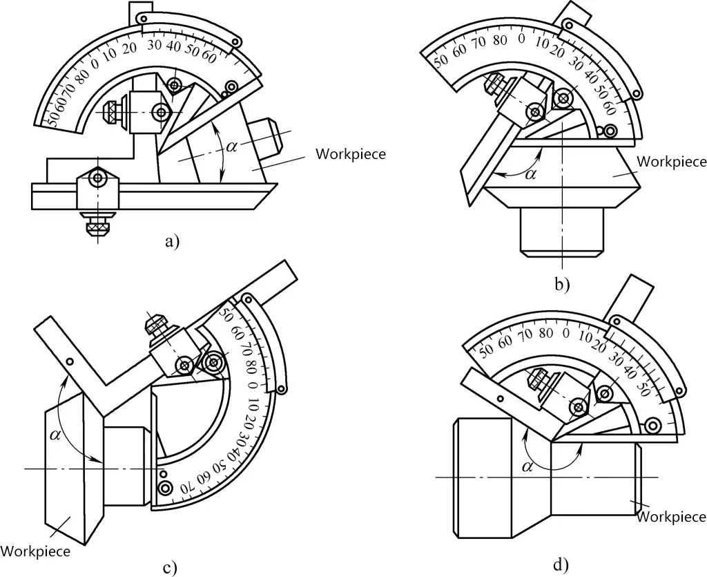
a) Measuring 0° to 50°
b) Measuring 50° to 140°
c), d) Measuring 140° to 230°
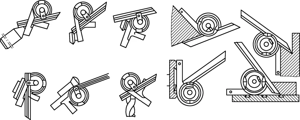
1) Before use, observe whether the zero line and end line of the vernier scale align with the corresponding lines on the main scale, and adjust if necessary. For errors that cannot be adjusted, make corresponding error additions or subtractions during measurement.
2) During measurement, ensure that the two measuring surfaces of the vernier universal protractor maintain good contact with the measured workpiece surface along the entire length, then tighten the nut on the brake before reading.
3) For Type I vernier universal protractor, when measuring angles from 0° to 50°, attach both the angle ruler and straight ruler; from 50° to 140°, attach only the straight ruler; from 140° to 230°, attach only the angle ruler; from 230° to 320°, do not attach either the angle ruler or straight ruler.
4) After measurement, promptly clean the main scale, straight ruler, angle ruler, etc., place them in a dedicated box, store them in the designated area according to storage requirements, and do not mix them with cutting tools or other tools.
5) If any abnormalities occur during use, promptly send it to the relevant department for repair.
V. Common Precision Measuring Tools and Their Use
1. Lever Micrometer
A lever micrometer (see Figure 13) is a micrometer that uses a lever transmission mechanism to convert the relative axial movement of two measuring surfaces on the frame into the rotational movement of the indicator pointer, reading small displacements between the two measuring surfaces at the micrometer level using the indicator.
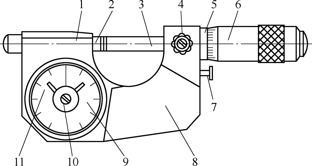
1—Frame
2—Movable anvil
3—Micrometer spindle
4—Locking device
5—Fixed sleeve
6—Thimble
7—Button
8—Heat insulation device
9—Indicator
10—Zero adjustment mechanism
11—Tolerance indicator
Its use is similar to ordinary outside micrometers, but it is suitable for inspecting large batches of precision parts. Lever micrometers with dial indicators of 0.001mm graduations can measure dimensions with tolerance grade 6; those with 0.002mm graduations can measure dimensions with tolerance grade 7.
(1) Absolute measurement
Place the workpiece to be measured in the correct position between the movable anvil and spindle of the lever micrometer. Adjust the thimble so that one of its lines aligns with the longitudinal line on the fixed sleeve, and the pointer on the dial has an appropriate reading. Then press the button several times to stabilize the reading. At this point, the reading on the thimble plus the reading on the dial is the actual size of the workpiece being measured.
(2) Relative measurement
Gauge blocks can be used as standards to adjust the lever micrometer, bringing the dial pointer back to zero. Then use the locking device to lock the spindle and read from the dial. This can avoid the influence of errors in the micrometer head reading and improve measurement accuracy.
When measuring, first press the button with your hand to retract the movable anvil, then place the workpiece between the two measuring faces. Release the button, press it once or twice, and the stable reading is the deviation value of the workpiece being measured.
2. Lever snap gauge
The lever snap gauge (see Figure 14) is a measuring instrument with a caliper-shaped frame. It is made using the lever-gear magnification principle, with common graduations of 0.001mm and 0.002mm. It can be used to measure the external dimensions of precision parts by comparison method, and can also measure geometric shape errors (such as roundness, cylindricity). It is suitable for inspecting large batches of precision parts with uniform size specifications.
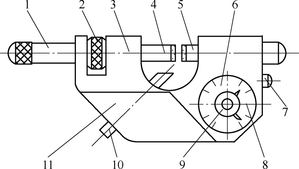
1—Brake handle
2—Adjustment nut
3—Frame
4—Adjustable measuring rod
5—Movable measuring head
6—Indicator device
7—Button
8—Tolerance indicator
9—Zero-setting device
10—Positioning pin
11—Heat insulation device
The measurement method of the lever snap gauge is similar to the relative measurement of the lever micrometer, using gauge blocks as standards to set the zero position.
When measuring, first press the button with your hand to retract the movable measuring head, then place the workpiece between the two measuring surfaces. Release the button to let the movable measuring head gently touch the measured surface, press once or twice, and after the reading stabilizes, observe the position of the pointer on the indicator mechanism and read the value. The reading is the deviation value of the workpiece being measured.
3. Lever gear comparator
The lever gear comparator (see Figure 15) is a measuring instrument that uses a lever and gear transmission system to convert the linear displacement of the measuring rod into an angular displacement of the pointer on an arc-shaped dial, and readings are taken from the dial. It is also called a lever gear micrometer.
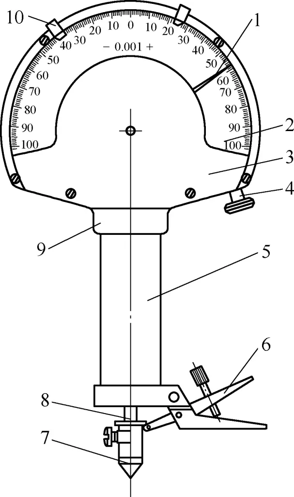
1—Pointer
2—Dial
3—Case
4—Zero-setting device
5—Axle sleeve
6—Fork
7—Measuring tip
8—Measuring rod
9—Body
10—Tolerance indicator
The lever gear comparator can measure the shape and position accuracy of external dimensions (such as radial runout, axial runout, etc.). Gauge blocks are used as standards for comparative measurement of length dimensions, and it is generally mounted on a special stand or workbench for use. Common graduations are 0.001mm and 0.002mm.
1) The comparator should be installed on a measuring workbench or other stable support for measurement. Before measuring, adjust the perpendicularity between the workbench plane and the axis of the comparator’s measuring rod.
2) During operation, the measuring rod should descend slowly, allowing the measuring tip to gently contact the workpiece or gauge block, avoiding impact on the measuring rod that could cause deformation or damage to the pointer.
3) When measuring, try to use the middle part of the dial graduations to improve measurement accuracy.
4) When inspecting batch workpieces, the tolerance indicator on the dial can be used to improve inspection efficiency.
5) When measuring workpieces of different sizes and shapes, an appropriate workbench can be selected.
4. Torsion spring comparator
The torsion spring comparator (see Figure 16), also known as a torsion spring micrometer, is a measuring instrument that uses a torsion spring element as a dimension conversion and magnification mechanism. It converts the linear displacement of the measuring rod into an angular displacement of the pointer on an arc-shaped dial, with readings taken from the dial.
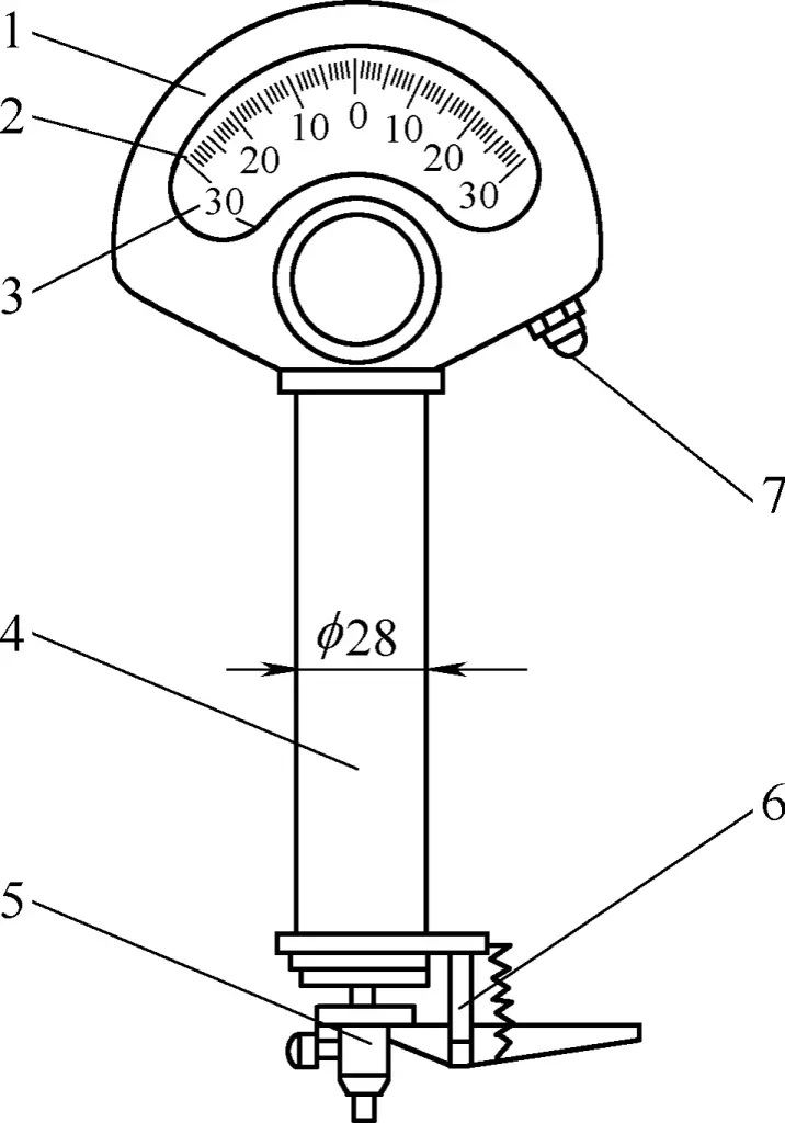
1—Case
2—Dial
3—Pointer
4—Sleeve
5—Measuring tip
6—Fork
7—Zero-setting device
It can be used to inspect external dimensions and shape accuracy of high-precision parts. It has high accuracy and good sensitivity, with no friction or clearance in the transmission mechanism, but improper use can easily damage the pointer and torsion spring. Common graduations include 0.002mm, 0.001mm, 0.0005mm, and 0.0002mm.
Its usage method is basically similar to that of the lever gear comparator, but due to the smaller indication range of the torsion spring comparator, more care is needed when adjusting the contact between the measuring tip and the workpiece. The measuring tip should never collide with the workpiece or workbench surface, and do not forcefully press the measuring tip or rod to avoid damaging the comparator.
5. Spirit level
The spirit level (see Figure 17) is a type of angle measuring instrument, mainly used to measure the flatness, straightness, and perpendicularity during equipment installation, and can also measure small angles of inclination of parts. Ordinary spirit levels used in the machinery industry are divided into bar type and frame type. The graduations of ordinary spirit levels are 0.02mm/m and 0.05mm/m.
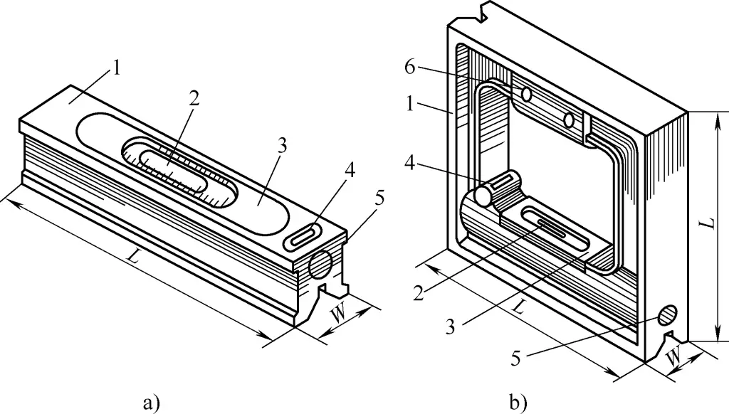
a) Bar-type spirit level
b) Frame-type spirit level
1—Main body
2—Main bubble vial
3—Cover plate
4—Secondary bubble vial
5—Adjustment mechanism
6—Insulated handle
Before measuring, check if the zero position of the spirit level is correct. If not, for adjustable spirit levels, the zero position should be adjusted.

