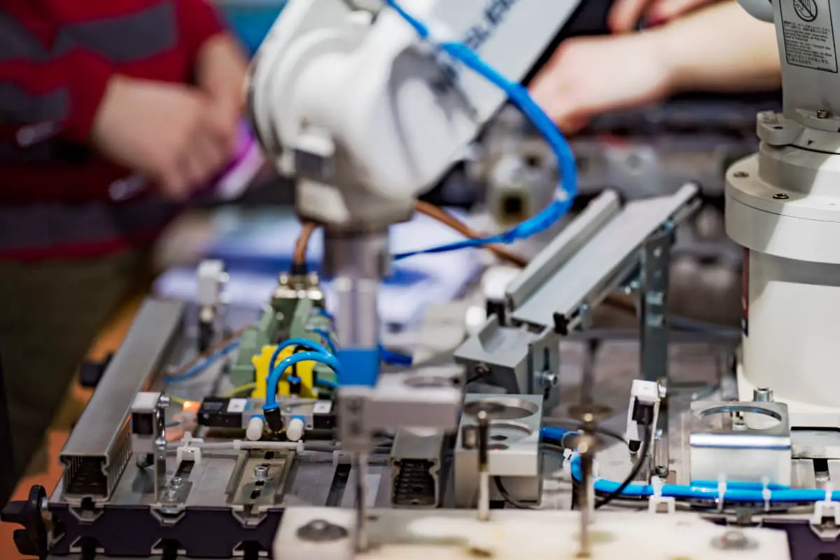
The mechanical assembly process is an important part of the mechanical manufacturing process and is also an important chapter that students should master. The content of this chapter includes basic concepts such as assembly, assembly precision, and assembly dimensional chain, as well as methods to ensure assembly precision.
I. Overview
1. Concept of Assembly
Any mechanical product is composed of many parts and components. The process of fitting and connecting parts or components according to specified technical requirements to form semi-finished or finished products is called assembly.
Parts are the most basic units that make up mechanical products. The process of fitting and connecting several parts together to form a certain part of a mechanical product (i.e., a component) is called sub-assembly. The process of further assembling parts and components into the final product is called final assembly.
The entry of components into assembly is hierarchical. Components that directly enter the final assembly of the product are usually called assemblies; components that directly enter the assembly of assemblies are called first-level sub-assemblies; components that directly enter the assembly of first-level sub-assemblies are called second-level sub-assemblies, and so on. The more complex the structure of the mechanical product, the more levels of sub-assemblies there are.
Assembly is not simply the process of connecting qualified parts, but requires a series of assembly process measures to ensure that the product meets quality requirements. Common assembly tasks include cleaning, connecting, correcting and adjusting, balancing, acceptance testing, as well as painting and packaging.
Assembly is the final stage in the entire mechanical manufacturing process. Assembly work has a significant impact on product quality. If assembly is not done properly, even if all parts are qualified, it may not be possible to produce qualified, high-quality mechanical products.
Conversely, if the manufacturing precision of parts is not high, but appropriate process methods are used during assembly, such as selective assembly, fitting, and adjustment, the product can still meet the specified technical requirements. Therefore, formulating reasonable assembly process procedures, adopting new assembly technologies, and improving assembly quality and labor productivity are important tasks in mechanical manufacturing technology.
2. Assembly Precision
(1) Concept of Assembly Precision
Assembly precision is a quality indicator specified during product design based on performance requirements that must be ensured during assembly. The assembly precision of a product generally includes the precision of mutual distances, positional precision, motion precision, and contact precision between parts and components.
1) Distance Precision
Distance precision refers to the precision of the distance dimensions between related parts and components, including fit requirements such as clearance and interference. For example, the equal height between the centerline of the spindle and the centerline of the tailstock sleeve in a horizontal lathe falls under this precision.
2) Positional Precision
Positional precision in assembly refers to the precision of parallelism, perpendicularity, coaxiality, and various circular runouts between related parts and components in a product.
3) Motion Precision
Motion precision refers to the precision in the direction of motion and relative motion speed between moving parts in a product. It mainly manifests as the precision of straightness, parallelism, and perpendicularity in the direction of motion, and the precision of relative motion speed, i.e., transmission precision.
4) Contact Precision
Contact precision refers to the size of the contact area and the distribution of contact points between mating surfaces and contact surfaces, such as gear meshing, the fit between a cone and a conical hole, and the contact precision requirements between guideway pairs.
(2) The Relationship Between Assembly Precision and Part Precision
Mechanical products are composed of many parts, and obviously, the assembly precision first depends on the precision of the related parts, especially the precision of key parts.
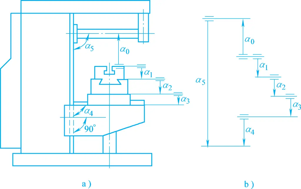
For example, the parallelism precision of the tailstock movement of a horizontal lathe relative to the saddle movement mainly depends on the parallelism of the bed guide rails A and B (see Figure 1). Similarly, the equal height A 0 of the spindle centerline and the tailstock sleeve centerline of the lathe mainly depends on the dimensional precision of A 1 , A 2 , and A 3 of the headstock, tailstock, and base plate (see Figure 2).
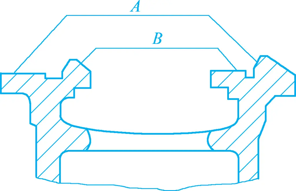
A—Saddle Movement Guide Rail
B—Tailstock Movement Guide Rail
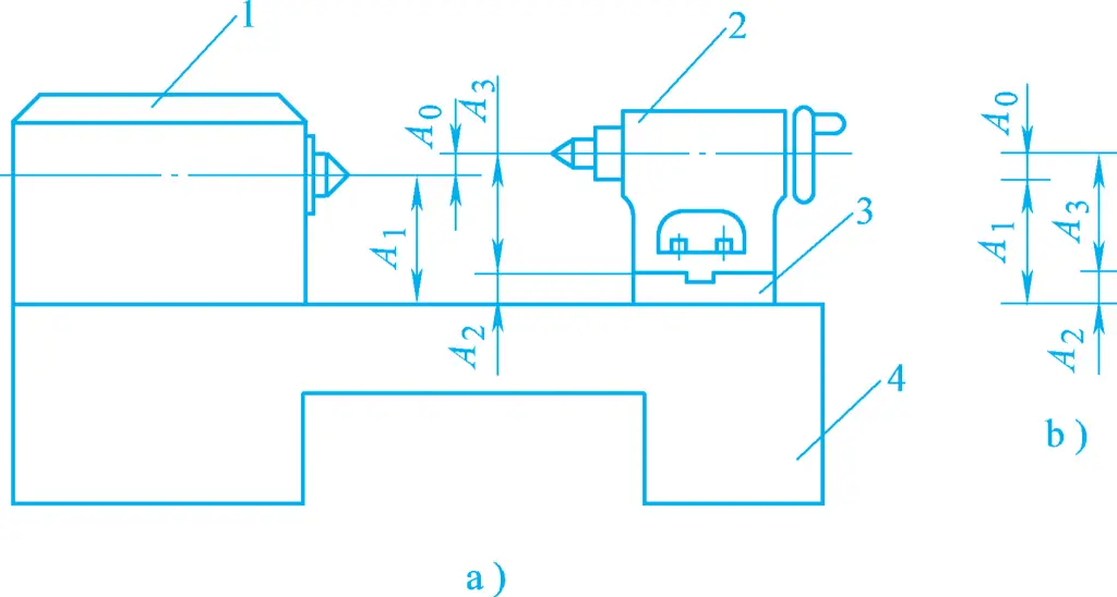
a) Schematic Diagram of Lathe Structure
b) Assembly Dimension Chain Diagram
1—Headstock
2—Tailstock
3—Base Plate
4—Bed
Secondly, ensuring assembly precision also depends on the assembly method. The precision requirement of the equal height A 0 shown in Figure 2 is very high. It is very uneconomical to achieve the precision requirement of A 0 by controlling the precision of dimensions A1 , A2 , and A3 .
In actual production, the related part dimensions A1 , A2 , and A3 are often manufactured according to economic precision, and the precision of the equal height A 0 is ensured by the process measure of fitting the base plate during assembly. Different process measures adopted in assembly will form various assembly methods, thus the relationship between assembly precision and part precision varies. The assembly dimension chain is an effective means for quantitative analysis of this relationship.
3. Introduction to Assembly Dimension Chain
(1) Concept of Assembly Dimension Chain
The dimension chain formed by the relevant dimensions (distances between surfaces or centerlines) or mutual positional relationships (parallelism, perpendicularity, or coaxiality) of related parts during the assembly process of a product or component is called an assembly dimension chain (see Figure 2b).
In the assembly dimension chain, each dimension is a link in the dimension chain, such as A1 , A2 , and A 3 , which are the relevant dimensions of parts or components entering the assembly, while the assembly precision index is often used as the closing link, such as A 0 . Obviously, the closing link is not a dimension on a single part or component, but a relative positional dimension between the surfaces or centerlines of different parts or components, formed after assembly.
Each link has machining errors, and the accumulation of errors of all links forms the error of the closing link. Therefore, applying the assembly dimension chain facilitates revealing the impact of cumulative errors on assembly precision, and calculation formulas can be listed for quantitative analysis and calculation, based on which reasonable assembly methods and tolerances for related part dimensions can be determined.
According to the geometric characteristics and spatial positions of each link, the assembly dimension chain can be divided into linear dimension chains, angular dimension chains, planar dimension chains, and spatial dimension chains, with the first two being the most common.
A linear dimension chain is composed of dimension chains of parallel straight lines (see Figure 2b), involving the precision of distance dimensions. An angular dimension chain is composed of dimension chains of angles (including parallelism and perpendicularity), with the geometric characteristics of each link mostly being parallelism or perpendicularity (see Figure 3), involving the precision of mutual positional relationships.
The key steps in applying the assembly dimension chain to analyze and solve assembly precision problems are threefold: the first step is to establish the assembly dimension chain, that is, to identify the links based on the closing link; the second step is to determine the method to achieve assembly precision; the third step is to perform the necessary calculations. The ultimate goal is to determine the economical, or at least feasible, tolerances for related part dimensions. The second and third steps often need to be carried out iteratively.
For example, for a certain assembly dimension chain, the complete interchange method was initially selected to solve the problem. After calculation, it was found that the precision requirements for the links were too high, so other assembly methods were considered, requiring corresponding calculations. Therefore, these two steps can be collectively referred to as the solution of the assembly dimension chain.
(2) Establishment of Assembly Dimension Chain
Correctly establishing the assembly dimension chain is the foundation for using the dimension chain principle to analyze and solve the relationship between part precision and assembly precision.
The closing link of the assembly dimension chain is mostly the assembly precision of the product or component. Identifying the part dimensions and positional relationships that directly affect assembly precision allows the identification of the links in the assembly dimension chain. It is evident that correctly identifying the links is key to establishing the assembly dimension chain.
The general method for identifying the links in the assembly dimension chain is: first determine the closing link based on the assembly precision requirements, then take the two parts at both ends of the closing link as the starting point, and along the direction of the assembly precision requirements, use the assembly reference surfaces of the parts as clues to identify the relevant parts affecting the assembly precision requirements until the same reference part or reference surface is found.
In this way, the dimensions or positional relationships between the assembly reference surfaces of directly connected adjacent parts on each relevant part are the links in the assembly dimension chain.
Of course, the assembly dimension chain can also be traced from one end of the closed loop, sequentially finding the related components until the other end of the closed loop. It can also start from a common reference surface or component and trace to both ends of the closed loop.
Regardless of the method used, the key issue is to correctly analyze the relevant dimensions and technical requirements of the components that directly affect the assembly accuracy being analyzed.
(3) Calculation of the assembly dimension chain
There are two methods for calculating the assembly dimension chain: the extreme value method (maximum-minimum method) and the probability method. The extreme value method for calculating the assembly dimension chain is the same as the calculation method for the process dimension chain. This method is characterized by its simplicity and reliability, but when the tolerance of the closed loop is small or there are many constituent loops, the tolerance of each constituent loop becomes too small, making processing difficult and increasing costs.
According to the basic principles of probability theory, first, in a stable process system, when processing in large batches, the likelihood of extreme errors in parts is very small. Secondly, during assembly, the likelihood of the “worst combination” of extreme errors in all parts occurring simultaneously is even smaller. If there are many constituent loops, the chance of the “worst combination” occurring during assembly is even smaller and can be practically ignored.
Obviously, the extreme value method is uneconomical as it reduces the tolerance of the constituent loops to ensure product qualification in extremely rare cases during assembly. On the other hand, the dimension chain calculation method based on the principles of probability theory, i.e., the probability method, is more reasonable in such cases. This part can be studied further in other books.
II. Methods to ensure assembly accuracy
The accuracy requirements of mechanical products are ultimately achieved through assembly. The assembly accuracy, structure, and production type of the product determine the assembly method used. Methods to ensure assembly accuracy in production include the interchange method, selective assembly method, fitting method, and adjustment method.
1. Interchange method
The interchange method is a method in the assembly process where the same type of components can be interchanged and still meet the assembly accuracy requirements. When using the interchange assembly method, the assembly accuracy mainly depends on the machining accuracy of the components. The essence of the interchange method is to control the machining errors of the components to ensure the assembly accuracy of the product.
When using the interchange method to ensure product assembly accuracy, there are two methods for determining the tolerance of components: the extreme value method and the probability method.
When using the extreme value method, if the sum of the tolerances of the relevant components (constituent loops) is less than or equal to the assembly tolerance (closed loop tolerance), the same type of components can be completely interchanged during assembly, meaning that the components can meet the assembly accuracy requirements without any selection, fitting, or adjustment. Therefore, it is called the “complete interchange method.”
When using the probability method, if the tolerance values of the relevant components (constituent loops) are appropriate and the production conditions are relatively stable, making the size distribution of each constituent loop relatively stable, the effect of complete interchange can also be achieved. Otherwise, some products will not meet the assembly accuracy requirements, so it is called the “incomplete interchange method,” also known as the “large number interchange method.”
Obviously, the probability method is suitable for large batch production. Using the incomplete interchange method relaxes the machining requirements for each constituent loop compared to the complete interchange method, reducing the machining cost of each constituent loop. However, a small number of products may not meet the assembly accuracy requirements after assembly. This problem can generally be solved by replacing 1-2 parts in the constituent loops.
Using the complete interchange method for assembly simplifies the assembly process, increases production efficiency, facilitates the organization of assembly lines and automated assembly, and is also conducive to organizing specialized production through collaboration.
Therefore, as long as the economic accuracy requirements for part machining can be met, the complete interchange method should be considered first for assembly regardless of the production type. However, when the assembly accuracy requirements are high, especially when there are many constituent loops, it becomes difficult to manufacture parts to economic accuracy. In this case, under large batch production conditions, the incomplete interchange method can be considered for assembly.
2. Selective assembly method
Under conditions of mass or batch production, when the assembly accuracy requirements are high and the number of constituent loops is small, if the complete interchange method is used for assembly, the small tolerance required for the constituent loops will make part machining difficult or even impossible. Since the number of constituent loops is small, the effect of using the incomplete interchange method for assembly is not significant. In this case, the selective assembly method should be considered.
The selective assembly method is an assembly method that enlarges the tolerance of the constituent loops in the dimension chain to an economically feasible level for machining, and then selects appropriate parts for assembly to ensure the assembly accuracy requirements.
There are three different forms of the selective assembly method: direct selective assembly, group assembly, and composite selective assembly.
(1) Direct selective assembly
During assembly, workers directly select suitable parts from many parts to be assembled to ensure the assembly accuracy requirements. This method is characterized by its simplicity, but the assembly quality and time largely depend on the skill level of the workers. Since the assembly time is not easily controlled accurately, it is not suitable for large batch production with strict production rhythm requirements.
(2) Group assembly
Group assembly, also known as group interchange method, enlarges the tolerance of the constituent loops several times compared to the complete interchange method, allowing them to be machined to economic accuracy. During assembly, the parts are first measured, grouped according to size, and then assembled according to the corresponding groups to meet the assembly accuracy requirements. Within each group, parts are completely interchangeable.
(3) Composite selective assembly
Composite selective assembly is a combination of direct selective assembly and group assembly, where the tolerance of parts can be appropriately enlarged. After machining, the parts are first measured and grouped, and then workers directly select parts within each corresponding group during assembly.
This method is characterized by unequal tolerances of mating parts, high assembly quality, fast speed, and the ability to meet certain production rhythm requirements. For example, the assembly of engine cylinders and pistons often uses this method.
3. Fitting method
In single-piece small batch or batch production, when the assembly accuracy requirements are high and the number of constituent loops in the assembly dimension chain is large, if the interchange method is used for assembly, the small tolerance required for the constituent loops will make machining difficult or even impossible. If the selective assembly method is used, it will be difficult to implement due to the relatively small batch size and the relatively large number of constituent loops. In this case, the fitting method is often used in production to ensure the assembly accuracy requirements.
The so-called fitting method is an assembly process method where the constituent loops in the assembly dimension chain are manufactured to economic machining accuracy, and during assembly, the cumulative error of each constituent loop is measured, and a predetermined constituent loop size is adjusted or locally fitted to reduce the cumulative error caused by manufacturing to economic accuracy, ensuring that the closed loop meets the specified accuracy.
In actual production, the following three common repair methods are often used:
(1) Single-piece repair method
During assembly, selecting a fixed part as the repair part to ensure assembly accuracy is called the single-piece repair method. This method is the most widely used in production.
(2) Combined machining repair method
This method involves combining two or more parts together as one part for repair. This reduces the number of components in the chain, thereby reducing the amount of repair work.
For example, in the assembly of a horizontal lathe tailstock, to reduce the scraping amount of the tailstock base plate during final assembly, the mating surfaces of the tailstock and the base plate are usually machined first, and the lateral small guide rails are scraped and fitted. Then, the two are assembled as one unit, using the bottom surface of the base plate as the reference, and the tailstock sleeve hole is bored to directly control the dimension from the tailstock sleeve hole to the bottom surface of the base plate. This way, the components A 2 and A 3 (see Figure 2) are combined into one, making it easier to ensure machining accuracy and allowing a smaller scraping amount for the base plate bottom surface.
Although the combined machining repair method has the above advantages, it brings inconvenience to machining, assembly, and production organization due to the need for parts to be matched. Therefore, it is mostly used in single-piece and small-batch production.
(3) Self-machining repair method
In machine tool manufacturing, using the machine tool’s own cutting capability to machine itself to meet certain assembly accuracy requirements is called the self-machining repair method.
This method is widely used in machine tool manufacturing. For example, during the final assembly of a shaper, planer, or gantry milling machine, the machine’s own worktable is planed or milled to ensure the parallelism accuracy between the worktable and the ram or guideway surfaces. On a lathe, the jaws of a self-centering chuck are machined to ensure the coaxiality accuracy between the spindle rotation axis and the working surfaces of the three jaws of the self-centering chuck.
The biggest advantage of the repair method is that each component can be manufactured to economic accuracy, and high assembly accuracy can be achieved. However, since each product needs to be individually repaired, there is no interchangeability, and the assembly labor is intensive, with low productivity and high technical requirements for assembly workers. Therefore, the repair method is mainly used in single-piece, small-batch, and medium-batch production where high assembly accuracy is required.
4. Adjustment method
The adjustment method involves machining each component in the dimensional chain to economic accuracy and ensuring assembly accuracy by replacing or adjusting the position of a pre-selected component during assembly. The component that is replaced or adjusted during assembly is called the adjustment part, and the component chain is called the adjustment chain. The adjustment method is similar to the repair method in principle, but the specific methods are different.
According to different adjustment methods, the adjustment method can be divided into movable adjustment method, fixed adjustment method, and error compensation adjustment method.
(1) Movable adjustment method
The method of ensuring assembly accuracy by adjusting the position of the adjustment part during assembly is called the movable adjustment method.
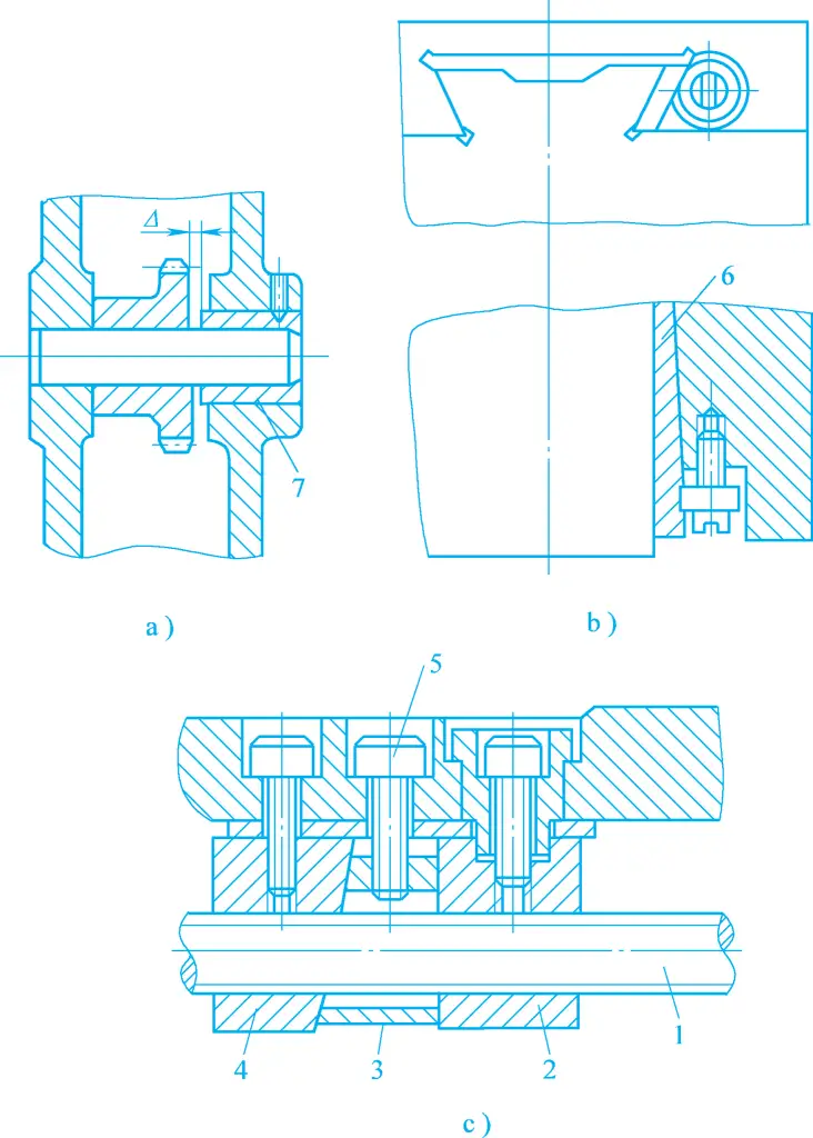
1—Lead screw
2, 4—Nut
3—Wedge block
5—Screw
6—Insert strip
7—Sleeve
The movable adjustment method is widely used in product assembly. Figure 4a shows adjusting the axial position of the sleeve to meet the axial clearance requirement of the gear; Figure 4b shows adjusting the position of the insert strip to ensure the fitting clearance of the guideway pair; Figure 4c shows adjusting the vertical position of the wedge block to adjust the axial clearance of the lead screw nut pair.
The movable adjustment method not only achieves ideal assembly accuracy but also allows re-adjustment of the adjustment part’s position to restore the original accuracy when assembly accuracy decreases due to part wear during product use. Therefore, this method is widely used in actual production.
(2) Fixed adjustment method
The method of ensuring assembly accuracy by replacing a pre-selected component in the dimensional chain during assembly is called the fixed adjustment method. The pre-selected component, known as the adjustment part, needs to be manufactured as a set of special parts with specific size intervals to be selected based on the cumulative error of each component during assembly.
Therefore, the selected adjustment parts should be simple in shape, easy to manufacture, and convenient to assemble and disassemble. Common adjustment parts include shims and sleeves. The fixed adjustment method is often used in large-batch and mass production where high assembly accuracy is required for multi-component dimensional chains.
(3) Error compensation adjustment method
During the assembly of products or components, adjusting the relative positions of relevant parts to partially offset their machining errors and improve assembly accuracy is called the error compensation adjustment method. This method is widely used in machine tool assembly. For example, during the assembly of a machine tool spindle, the radial runout of the spindle is controlled by adjusting the radial runout direction of the front and rear bearings.
In summary, when assembling mechanical products, the assembly method should be reasonably selected based on factors such as the product’s structure, assembly precision requirements, the number of links in the assembly dimension chain, production type, and specific production conditions. Generally, as long as the processing of the constituent links is relatively economical and feasible, the complete interchange method should be preferred.
If the production batch is relatively large and there are many constituent links, the incomplete interchange method should be considered. When the interchange method makes the processing of the constituent links difficult or uneconomical, other methods can be considered: for large-scale mass production with fewer constituent links, the group assembly method can be considered; for more constituent links, the adjustment method should be used. For single-piece small batch production, the fitting method is commonly used, and for batch production, the fitting method can also be used as appropriate.

