I. Commonly Used Tools and Measuring Instruments
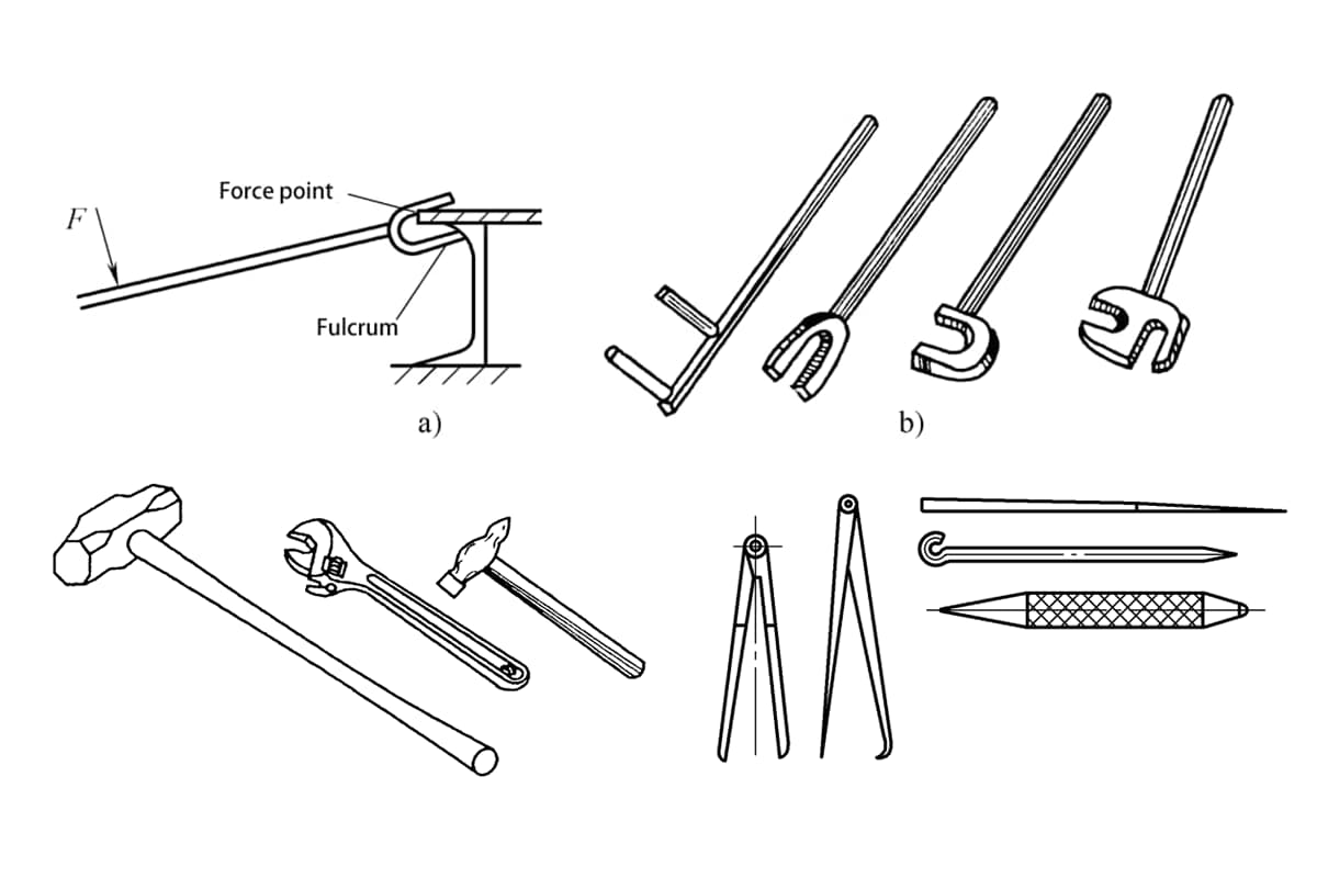
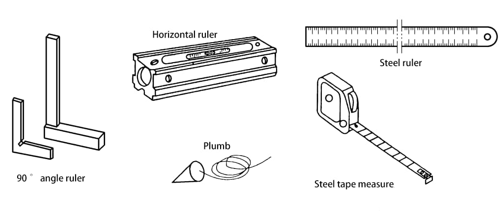
Common tools include sledgehammers, hammers, chisels, angle polishers, hand grinding wheels, crowbars, wrenches, jacks, and various marking tools, etc. Common measuring instruments include steel tape measures, steel rulers, levels, 90° squares, plumb bobs, and various positioning templates for inspecting parts. Figure 3-1 shows several common simple crowbars, Figure 3-2 shows a schematic of several commonly used assembly tools, and Figure 3-3 shows a schematic of commonly used assembly measuring instruments.


II. Commonly Used Assembly Equipment
1. General requirements for assembly equipment
To ensure the dimensional accuracy of products after assembly, the surface of the platform or fixture should be smooth and flat, and it should be placed horizontally; for larger assembly fixtures, they should be placed on a fairly solid foundation to prevent the foundation from sinking and causing deformation of the fixture; the fixture should facilitate assembly operations such as loading, unloading, positioning, and welding; the selected equipment should be simple in construction, easy to use, easy to maintain, and low in cost.
2. Assembly platform
(1) Cast iron platform
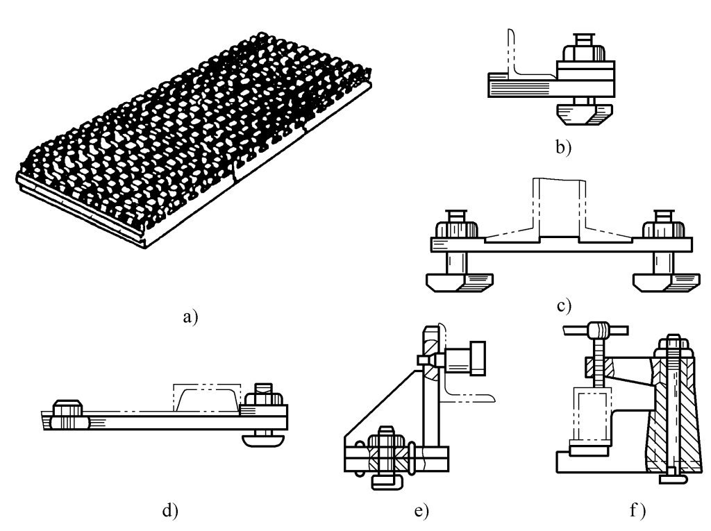
This platform is made of many pieces of cast iron, with a sturdy structure and a relatively high flatness of the workpiece surface. It has many holes on the surface for installing fixtures. It is commonly used for assembly and for the hot processing bending of steel plates and structural steel (see Figure 3-4).
(2) Steel structure platform
This platform is welded from structural steel and thick steel plates. Its upper surface is generally not machined, so its flatness is poorer. It is commonly used for welding large steel structures or making truss structures.
(3) Guide rail platform
This platform consists of many guide rails installed on a cement foundation. The upper surface of each guide rail is machined and has bolt grooves for fastening workpieces (see Figure 3-5). This platform is used for making large structural components.

(4) Cement Platform
The cement platform is a simple and suitable platform for large-area work, made by pouring cement. Before pouring, stakes and rings are embedded in certain positions to fix the workpiece during assembly.
On the surface of the cement platform, cross-shaped flat steel is also placed (aligned with the cement surface) as a conductive plate or for fixing workpieces. This type of cement platform can be assembled with steel plates, frames, and components, and tire racks can be placed on it for assembling larger parts.
(5) Electromagnetic Platform
The electromagnetic platform consists of a platform (welded from section steel and steel plates) and electromagnets. The electromagnets of the electromagnetic platform can tightly fix steel plates or section steel on the platform, reducing deformation during welding. The function of the inflatable hose and flux is to form a flux pad for submerged arc welding, which can prevent slag leakage and molten iron from flowing down.
Figure 3-6 shows the use of the electromagnetic platform in conjunction with the flux pad device. In the middle of the trolley is a canvas flux trough 6, two compressed air hoses with diameters of 50~65mm, 2 and 4, can be inflated to raise the flux pad and press tightly against the back of the weldment to ensure good back formation of the weld seam during single-sided welding and double-sided forming.
The electromagnetic latches 8 on both sides are used to tightly hold the steel plates, preventing misalignment, movement, and reducing angular deformation. The support rollers 5 rise after the compressed air hose 3 is inflated, facilitating the loading and unloading of strips and alignment of the seams.
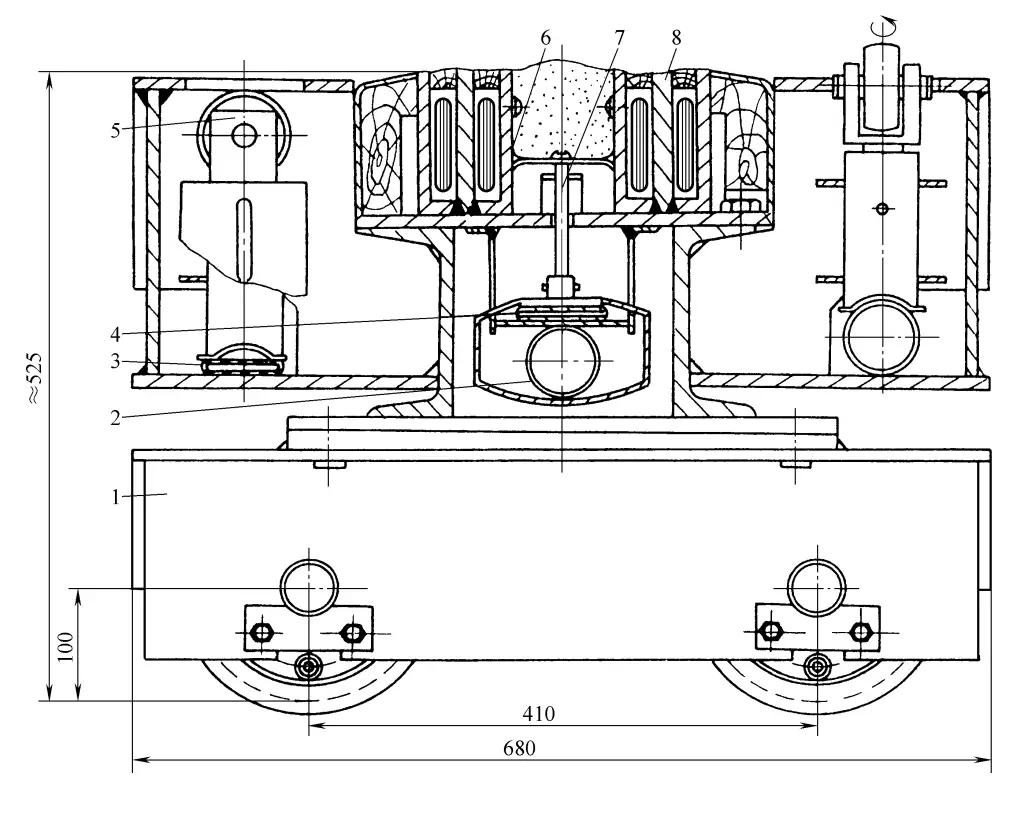
1—Mobile Trolley
2, 3, 4—Compressed Air Hoses
5—Support Roller
6—Canvas Flux Trough
7—Flux Pad Support
8—Electromagnetic Latch
3. Tire Frame
The tire frame, also known as the mold frame, is used when the structure of the workpiece is not suitable for support by an assembly platform (such as ships, locomotive vehicle chassis, aircraft, and various container structures), requiring the manufacture of an assembly tire frame to support the workpiece during assembly. Therefore, tire frames are often used for some complex-shaped, high-precision structural components.
Its main advantage is the use of fixtures for convenient and precise positioning of various parts. Some tire frames can also be designed to be reversible, flipping the workpiece to a position suitable for welding. Using tire frames for assembly can improve assembly accuracy and speed, but since the production cost of tire frames is high, they are often designed and manufactured for specific products, suitable for assembly lines or batch production (see Figure 3-7).
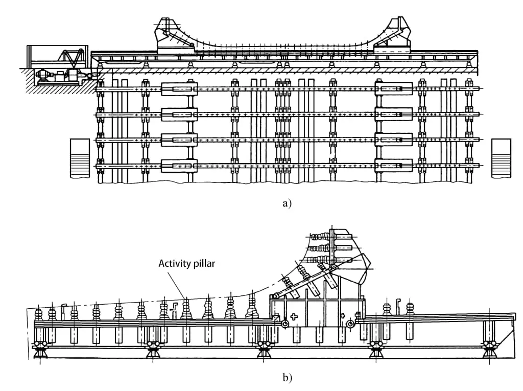
a) Tire Frame b) Partial Enlargement
Additionally, turning the tire also belongs to the assembly tire frame, mainly used for assembling cylindrical workpieces of various diameters. When making a tire frame, the following points should be noted:
- The shape of the tire frame working face should be adapted to the shape of the part of the workpiece that is supported.
- The structure of the tire frame should facilitate operations such as loading, unloading, positioning, clamping, and welding of the workpiece during assembly.
- The tire frame should have center lines, position lines, horizontal lines, and inspection lines marked on it to facilitate the correction and inspection of the workpiece at any time during assembly.
- The fixtures on the tire frame should use quick clamping devices as much as possible and have sufficient clamping force; positioning elements need to be dimensionally accurate and wear-resistant to ensure precise positioning of parts.
- The tire frame must have sufficient strength and rigidity, and be placed on a solid foundation to avoid foundation subsidence or deformation of the tire frame affecting the shape and size of the product during assembly.

