Manual Correction: Techniques for Thin & Thick Steel Plates, and Profiles
Have you ever wondered why sheet metal parts sometimes don’t fit together perfectly? This article explores the fascinating world of…
Mechanical correction is the process of correcting deformed workpieces and deformed steel materials using mechanical equipment. The equipment used for mechanical correction includes roller straighteners, round rollers, specialized flatteners, straightening machines, and various presses, such as mechanical presses, hydraulic presses, screw presses, etc.
Table 1 Methods of Mechanical Correction and Their Application Range
| Category | Sketch | Application Range | |
| Stretching Machine Correction | 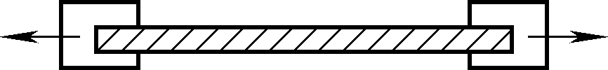 | Warping of thin plates, twisting of profiles, straightening of pipes and wires | |
| Press Correction | 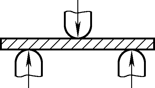 | Localized correction of plates, pipes, and profiles | |
| Jacks Correction | 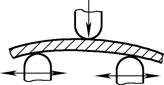 | Straightening of angle steel, channel steel, and I-beams, also usable for bending | |
| Roll-Type Correction Machine | Straight Roll | 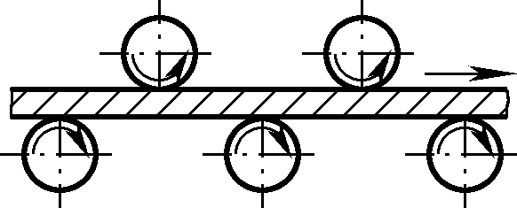 | Correction of plates, pipes, and profiles |
| Inclined Roll | Correction of round-section materials | ||
 | Precision correction of thin-walled tubes with circular cross-sections | ||
 | Correction of thick-walled circular tubes and rods | ||
The correction accuracy achievable by mechanical correction can be found in Table 2.
Table 2 Correction Precision of Commonly Used Correction Equipment
| Equipment | Correction Range | Correction Accuracy (mm) | |
| Roll-Type Correction Machine | Multi-roll Plate Correction Machine | Plate leveling | 1.0~5.0 |
| Multi-roll Angle Steel Correction Machine | Angle Steel | 1.0 | |
| Straightening and Cutting Machine | Straightening and cutting of coil materials (wire, rod, flat steel, strip) | 0.5~0.7 | |
| Inclined Roll Correction Machine | Straightening of round-section tubes and rods | Rough Materials 0.5–0.9 Finished Materials 0.1–0.2 | |
| Press Machine | Horizontal Bending Press | I-beams, channel steel, rod-like welded components | 1.0 |
| Vertical Bending Press | |||
| Hand Press | Straightening of rough materials | Finished Materials 0.05–0.15 | |
| Friction Press | |||
| Hydraulic Press | I-beams, channel steel, H-beams, rod-like welded components | ||
The deformation of steel plates is generally corrected on multi-roll leveling machines. When leveling, the thicker the steel plate, the easier it is to correct; the thinner the plate, the easier it is to deform, making correction more difficult.
Leveling machines can be classified by the number of rolls, such as five-roll, seven-roll, nine-roll, up to twenty-one rolls, etc. In terms of relative position, they can be classified as parallel-type and non-parallel-type. Large multi-axis leveling machines can correct steel plates up to 50mm thick and 2000mm wide.
Usually, steel plates with a thickness of more than 3mm are leveled on a five-roller or seven-roller leveling machine, while thin steel plates with a thickness of less than 3mm must be leveled on a nine-roller, eleven-roller, or more multi-roller leveling machine.
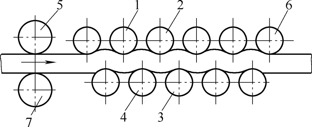
The basic principle of steel plate leveling is shown in Figure 1. Rollers 5 and 7 are feeding guide rollers, roller 6 is the discharging guide roller, and the rest are working rollers.
When the plate is fed between the upper and lower rollers, rollers 1, 2, and 4 form a group to bend the plate upwards, and rollers 2, 3, and 4 form a group to bend the plate downwards. Through repeated bending and stretching beyond the yield limit, the originally “tight” areas are stretched, balancing with the previously “loose” areas. This creates the so-called plastic flow, achieving the goal of leveling.
The pressure of the upper rollers of the leveling machine directly determines the gap between the rollers. When the pressure of the upper rollers is moderate, only the “tight” areas of the plate are stretched, balancing with the “loose” areas, and the plate is leveled. This is the ideal state. When the pressure of the upper roller is insufficient, although the “tight” areas of the plate are stretched, they do not balance with the “loose” areas, and the plate is not completely leveled.
When the pressure of the upper roller is too high, not only the “tight” areas are stretched, but the “loose” areas are also stretched to varying degrees. Although the extent of stretching is balanced and the plate is leveled, the grains of the plate are distorted and broken, causing excessive cold work hardening, thereby reducing the plate’s service life. Therefore, determining the appropriate pressure of the upper roller directly affects the leveling result of the plate.
The pressure of the upper rollers on the leveling machine (i.e., the gap between the rollers) is generally adjusted so that the feeding guide rollers (such as rollers 5 and 7 in Figure 1) exceed the thickness of the plate by 2–3mm (to facilitate the insertion of the plate to be leveled), while the discharging end equals the thickness of the plate. The working rollers are adjusted based on the thickness of the plate, with the front end smaller than the plate thickness by 1–5mm, gradually increasing toward the rear, until the discharging guide rollers are adjusted to be equal to the plate thickness.
However, in actual leveling processes, this method is inconvenient to measure, so experience-based methods are commonly used in practice to determine the pressure of the upper roller of the leveling machine.
Insert a plate strip of the same thickness as the plate to be leveled into the leveling machine. Adjust the pressure by hand until the rollers are in contact with the plate strip and apply a certain pressure. Also observe the height and left-right level of the upper rollers. After the strip is rolled out of the leveling machine, check its flatness and conduct another trial leveling and adjustment. This pressure is called the base pressure.
Then insert the plate to be leveled. After rolling, check the flatness of the plate and listen to the machine’s load noise to judge whether the upper roller pressure is appropriate. If the pressure is not suitable, fine adjustments can be made, or after rolling a section, fine-tune again. The final pressure determined is called the actual working pressure. After that, batch leveling can be carried out according to this pressure.
Feed the plate into the leveling machine, use a hand or lever to press down the upper roller, and judge whether the pressure is appropriate by the resistance felt. Then, visually inspect whether the upper roller bearing seats are at the same height, and whether the rollers are horizontally aligned. Start the leveling machine, and after the plate is fed to the supporting rack, adjust the pressure according to the flatness of the plate and the rotation of the rollers.
If a certain upper roller does not rotate or rotates intermittently, it indicates that the pressure on that roller is insufficient. If all upper rollers rotate, there is a certain pressure applied. If misalignment is observed, it means that the pressure on the misaligned side is too high, while the other side’s pressure is too low. Adjust accordingly based on the excessive or insufficient pressure. If, after cutting the coiled plate into smaller segments, large areas remain uneven, the pressure is still insufficient, and further pressure is needed.
As for the pressure of the discharging guide rollers, it can be fine-tuned based on the upward or downward bending of the plate end after it exits the leveling machine.
The leveling machine can be used to level a wide range of plates, such as coils, convex plates, wavy plates, and loose pieces. The main leveling operation methods include the following aspects.
According to the method mentioned above for determining the pressure of the upper roller, adjust the working rollers to the working pressure, raise the feeding guide roller 5, lift the coil, and insert one end of the coil between the feeding guide rollers 5 and 7. Gradually start the leveling machine so that the coil slowly enters a certain distance (about 1–2 working rollers). Then adjust the position of the leading plate end by moving the crane in all directions, ensuring that it is parallel to the outer contour of a certain upper or lower roller (observed from the side) to prevent the plate from running off course. Then, press down the upper feeding guide roller 5 and apply heavier pressure to prevent the coil from dislocating when placed on the coil cradle. Finally, start the machine and release the plate.
By observing the flatness of the plate delivered to the cradle and listening to the machine’s load noise, one can judge whether the pressure of the upper rollers is appropriate. After necessary adjustments, bulk leveling corrections can follow.
Narrow strips cut by the shearing machine tend to twist and deform due to the slanted cutting edge, along with flat and upright bending deformations.
These strips can also be leveled using the leveling machine. The leveling method is: Adjust the base pressure of the upper rollers as previously described, raise the upper feeding guide roller 5 to be slightly higher compared to a plate of the same thickness, to accommodate the difficulty of inserting twisted strips. The working roller pressure should be slightly higher than that of leveling a plate of the same thickness, to induce excessive plastic deformation for better leveling results.
Depending on the degree of leveling required, the strip can be passed through the machine a second or third time, but the strip should be reversed, and slight additional pressure applied for optimal leveling results. This method is less effective for upright bending of the strips, which may need manual correction after exiting the machine.
It should be noted that the leveling method described above can cause slight thinning and stretching of the strips.
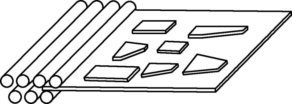
For thinner individual plates, a thicker steel plate can be used as a support plate, with the thinner plate placed on top for leveling. Alternatively, several long thin plates can be stacked together for leveling, as shown in Figure 2.
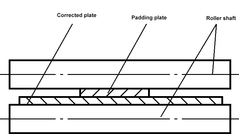
For plates with a flat middle but wavy edges, insert a support plate in the flat middle section to thin and stretch it, achieving leveling, as shown in Figure 3.
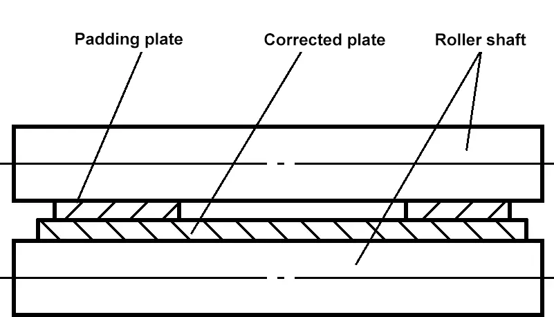
For sheet metal with a wavy middle section but flat sides, padding can be added to the sides to thin them and achieve correction, as shown in Figure 4.
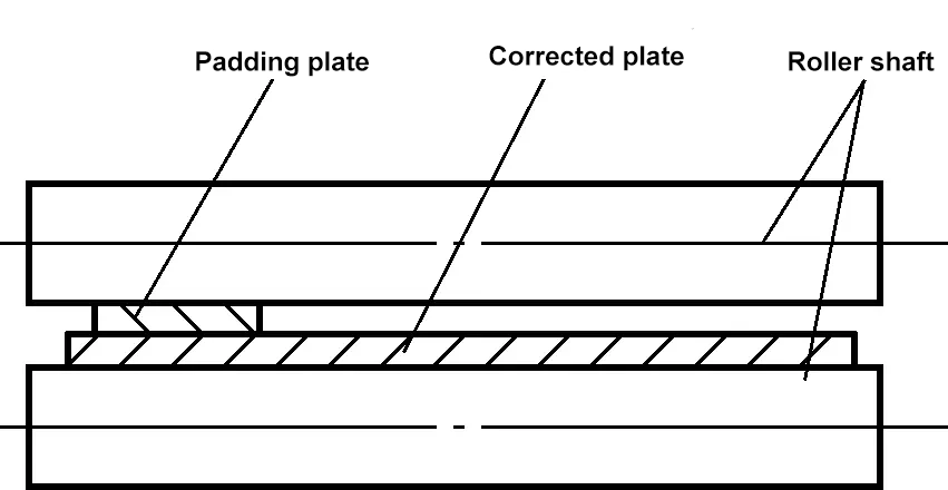
For sheet metal with one wavy side and one flat side, padding can be added to the flat side to thin and stretch it, achieving correction, as shown in Figure 5.
Additionally, pressure can be directly applied to the flat side to stretch and thin it, thereby achieving correction, as shown in Figure 6.
(7) Correction of flat bending on a three-roll bending machine
Steel plates cut by hot cutting tend to form vertical bends, with flat bends and twists being rare. Steel strips cut on an inclined shear machine tend to form compound bends, i.e., vertical bends, flat bends, and twists, with the thinner the plate, the more obvious the effect. A leveling machine can only correct flat bends and remove partial twisting, while a three-roll bending machine can correct both flat bends and twists.
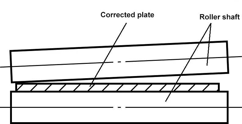
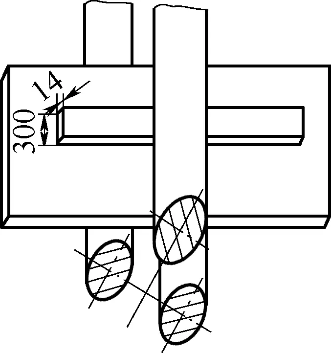
Figure 7 shows a schematic of correcting a 14mm×300mm×2560mm steel plate cut by an inclined shear machine. During operation, a 32mm thick pad is placed into the bending machine, and then the steel strip is vertically rolled into the machine. The upper axis roller is lowered and repeatedly rolled back and forth to correct the flat bend and remove partial twist. The extent to which the upper roller is lowered depends on the correction, but under no circumstances should the pad bend upwards.
The prerequisite for using this method is that the pad must be quite thick, generally between 30 to 40mm, and the greater the rigidity difference between the pad and the plate being corrected, the better.
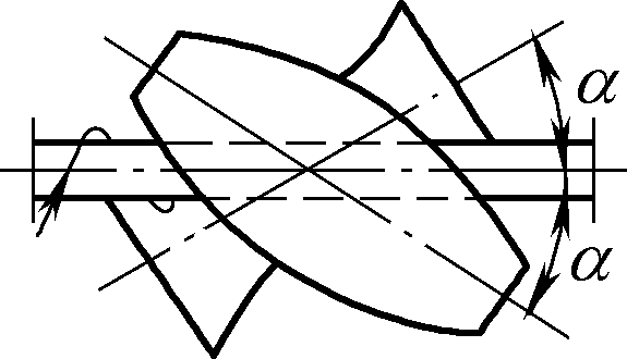
When correcting the twist of steel strips, the steel strip should be set at a certain angle to the axis roller. Due to varying degrees of twist, the angle of inclination is difficult to determine in advance and is generally adjusted based on the amount of pressure applied and the observed correction effect. The correction process should start light and gradually increase pressure, observing the effect before proceeding to batch correction. Over-tightening must be avoided, as it could lead to reverse twisting, making the situation worse.
Figures 8a and 8b respectively show methods for correcting steel strips twisted to the right and left. The correction effect depends on the angle at which the material is placed on the axis roller, but is unrelated to which end is fed first.
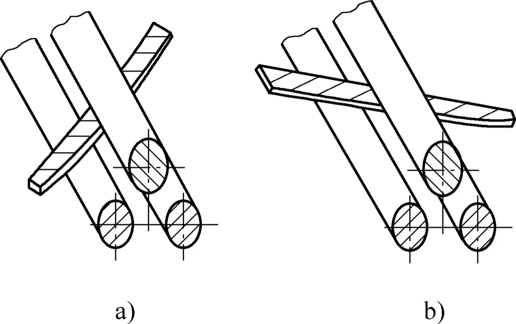
If padding is placed under the material, it is impossible to correct the twist, as the pad cannot bend upwards.
The mechanical correction of pipes, steel sections, and other profiles is mostly done using cold correction, which involves the use of multi-roll section straighteners, profile stretchers, and presses.
The working principle of a multi-roll profile straightener is similar to that of a sheet leveling machine. The difference is that the correction roller is a contour-adapted roller aligned with the cross-section of the profile being corrected, as shown in Figure 9. When correcting different profiles, rollers with varying contours can be used.
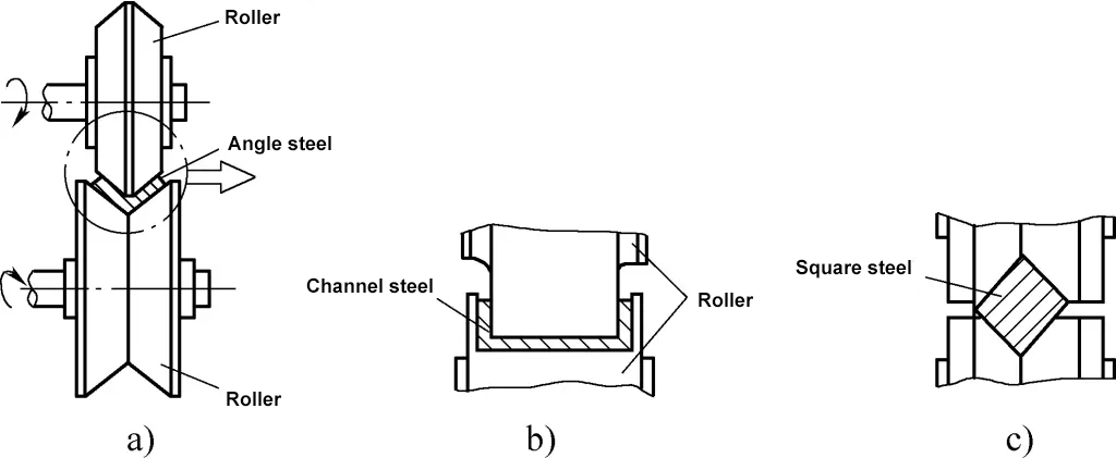
a) Angle steel correction
b) Channel steel correction
c) Square steel correction
Similar to the principle of sheet leveling, profiles pass through upper and lower rows of rollers and are repeatedly bent, thus stretching the fibers and achieving correction. In straight roller machines, the roll axis lines are parallel, making them suitable for various profiles. In slant-roll machines, the roll outlines are hyperbolic, and the rollers are mostly arranged in upper and lower groups (2-3 rollers per group), with the roller axis slanted. This induces additional rotational motion in round materials, enhancing the correction effect, making it suitable for the correction of pipes, rods, and wires.
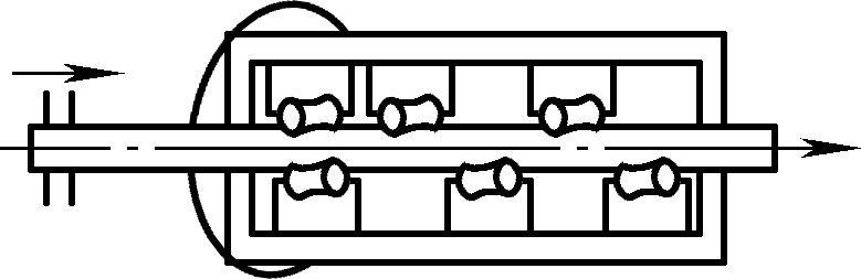
The bending deformation of steel sections and various welded beams can be corrected using the reverse bending method with a profile stretcher. The stretcher is horizontally arranged, and the moving parts are typically double-headed (see Table 1 figures).
During operation, the profile steel is placed between the support and the pusher. The protruding part is blocked by the pusher and pressed toward the support while it can move along the length. The position of the support can be adjusted by operating the handwheel to accommodate different degrees of bending of the profile steel. When the pusher is driven by the motor to move horizontally back and forth, it periodically applies thrust to the profile steel being corrected, causing reverse bending to achieve the purpose of correction.
The initial position of the pusher can be adjusted to control the amount of deformation. The table is equipped with rollers to support the profile steel and reduce friction during its back-and-forth movement. The profile steel straightening machine can also be used for bending the profile steel, making it a dual-purpose machine for both bending and correction.
The straightening principle, sequence, and method for straightening profiles and various welded beams with a press are the same as for thick plate materials, but during operation, the placement position of the workpiece, the pressing location, the thickness of the shim, and the placement area should be reasonably set according to the size and deformation of the workpiece to improve the quality and speed of straightening. Figure 10 shows a schematic diagram of straightening metal profiles with a press.
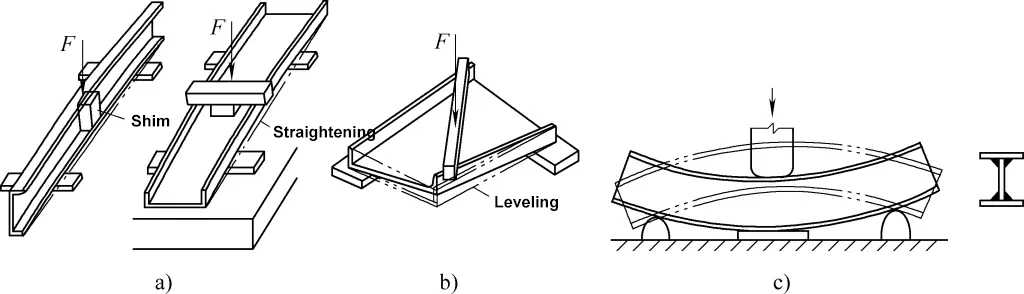
a) Channel Steel Bend Straightening
b) Channel Steel Twist Straightening
c) I-Beam Bend Straightening