I. Shafts
The shaft is used to install and fix mechanical parts such as gears, rotating wheels, and pulleys, to output rotational motion or vibration.
1. Classification of Shafts
(1) Classification by load type
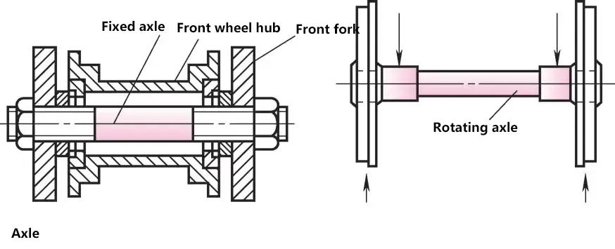
1) Axle. A shaft that only bears bending loads during operation and does not transmit torque. Axles are divided into fixed axles (such as shafts supporting pulleys, bicycle front axles) and rotating axles (such as railway vehicle axles) based on whether they rotate or not.
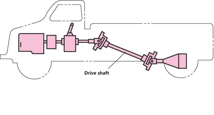
2) Drive shaft. A shaft that transmits torque during operation but does not bear or bears very little bending load, such as the shaft between a car’s gearbox and rear axle.
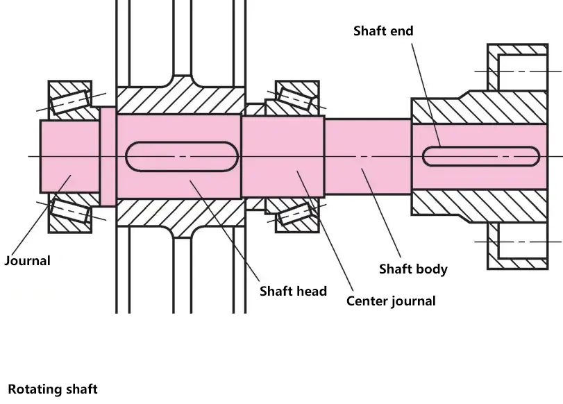
3) Spindle. A shaft that both bears bending loads and transmits torque during operation.
(2) Classification by shaft shape
1) Straight shaft. Divided into plain shafts and stepped shafts. Plain shafts have the same outer diameter, simple shape, and are easy to process; stepped shafts have different diameters in different sections and are widely used in machinery.

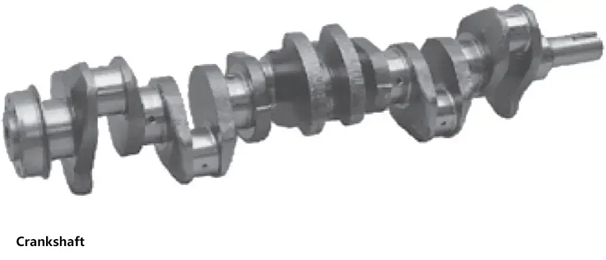
2) Crankshaft. Used in transmission mechanisms of various internal combustion engines, steam engines, etc.
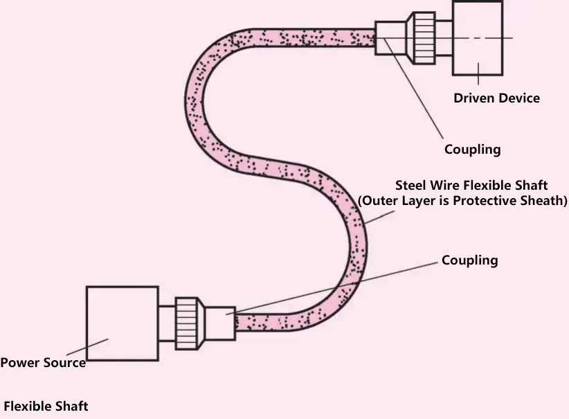
3) Flexible shaft. Used to connect two shafts that are not on the same axis, not in the same direction, or have relative motion, to transmit rotational motion and torque.
2. Shaft Structure
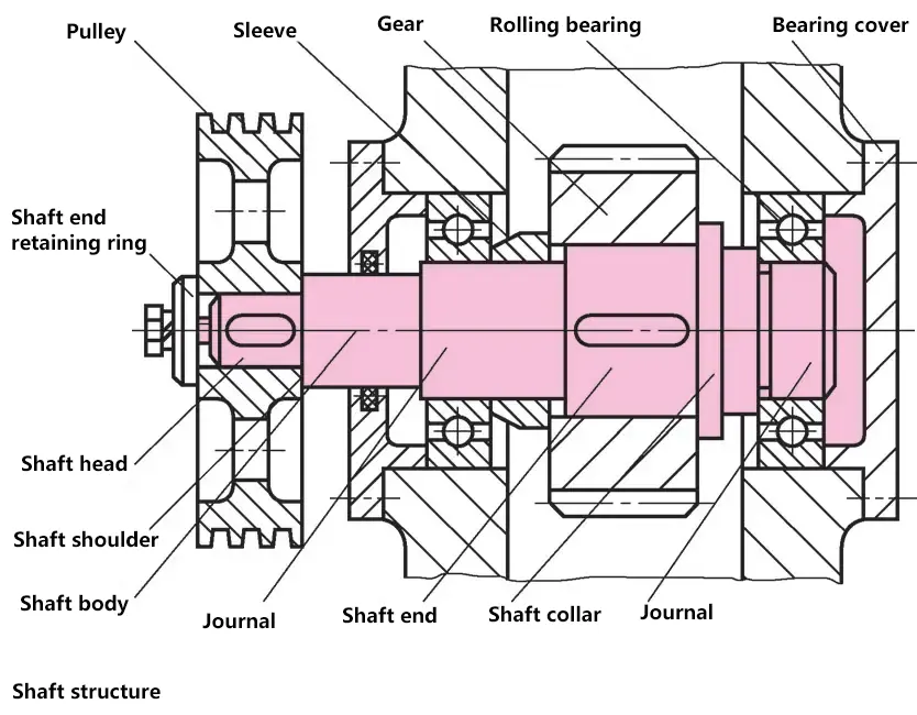
(1) Journal
The part of the shaft that fits with the bearing, its diameter should conform to the bearing inner diameter standard.
(2) Shaft end
The part of the shaft where the hub is installed, its diameter should match the hub inner diameter of the mating part and adopt standard diameters.
(3) Shaft body
The part connecting the journal and the shaft end.
(4) Shaft shoulder, shaft collar
The stepped part used for axial fixing of parts is called a shaft shoulder, and the ring-shaped part is called a shaft collar.
Note:
- For ease of assembly, the ends of the journal and shaft end should have chamfers.
- The diameter of threaded or splined parts on the shaft should conform to thread or spline standards.
- The length of each section of the shaft is determined by the width of mating parts, overall structure, and assembly/disassembly process.
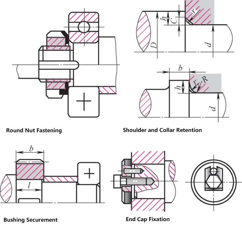
3. Fixing of Parts on Shafts
Common methods for positioning and fixing parts on shafts include round nuts, shaft shoulders and collars, sleeves, shaft end retaining rings, snap rings, shaft end plates, set screws, tapered key connections, pin connections, and interference fits.
4. Common Process Structures on Shafts
The processability of shaft structure refers to the structural form of the shaft that should be easy to process, easy to assemble and maintain parts on the shaft, and able to improve productivity and reduce costs. Generally, the simpler the shaft structure, the better its processability. Under the premise of meeting usage requirements, the structural form of the shaft should be simplified as much as possible.
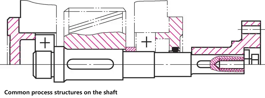
1) The structure and shape of the shaft should be convenient for processing, assembly, and maintenance.
2) The diameter of stepped shafts should be larger in the middle and smaller at both ends to facilitate the assembly and disassembly of parts on the shaft.
3) The transition areas between the shaft end, journal, and shoulder (or collar) should have chamfers or fillet radii to facilitate the assembly of parts on the shaft, avoid scratching mating surfaces, and reduce stress concentration. The chamfers (or fillet radii) should be made consistent as much as possible to facilitate processing.
4) When threads need to be cut or grinding needs to be performed on the shaft, there should be thread relief grooves and grinding wheel overrun grooves.
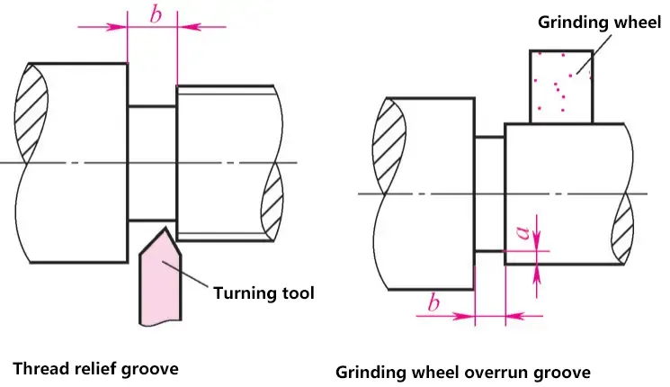
5) When there are two or more keyways on the shaft, the groove widths should be as consistent as possible and arranged on the same line to facilitate processing.
II. Springs
Springs are parts made of elastic materials that deform under external force and return to their original state when the force is removed.
Springs can be classified by load bearing as tension, compression, torsion, and bending springs; by shape as helical, ring, disc, and flat springs.
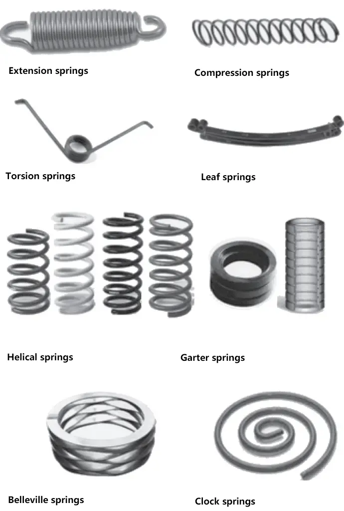
(1) Tension springs
Measure force and torque, such as springs in spring scales and dynamometers.
(2) Compression springs
Used in medical respiratory equipment, medical mobile devices, hand tools, home care equipment, vibration reduction, engine valve springs, etc.
(3) Torsion springs
Control the movement of mechanisms or the position of parts, such as springs in clutches, brakes, cam mechanisms, valves, and governors, and brake springs in cars and bicycles.
(4) Bending springs
Buffer and absorb vibration, such as vehicle suspension and springs in various shock absorbers.
(5) Helical springs
Commonly used in balancing mechanisms in machinery, widely applied in automotive, machine tools, electrical appliances, and other industrial production.
(6) Ring springs
Applied in situations where space is limited and strong buffering is required.
(7) Disc springs
Strong buffering springs for heavy machinery, aircraft, etc., widely used in clutches, pressure relief valves, sealing rings, and automatic control mechanisms.
(8) Flat springs
Store energy as a power source, such as mainsprings used in mechanical clocks, instruments, and toys.
III. Sealing of Parts
Various shafts pass through the outer walls of machines, gearboxes, bearings, or valve bodies. To prevent dust, dirt, water, and harmful media from entering the machine body and to prevent lubricants or working media from leaking out of the machine body, sealing devices are necessary.
Rotating shafts, axles, and spindles perform rotational motion, while pistons perform reciprocating motion. Sealing should not affect rotational and reciprocating motions while isolating spaces from each other.
1. Contact Sealing
(1) Packing materials
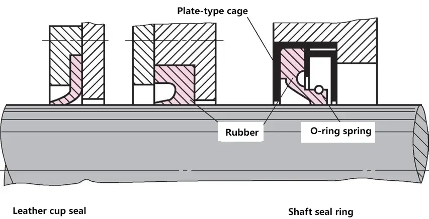
Mainly used for sealing spindles and low-speed reciprocating piston rods, generally using fibers, metal fibers, soft metals, or other non-forming sealing materials.
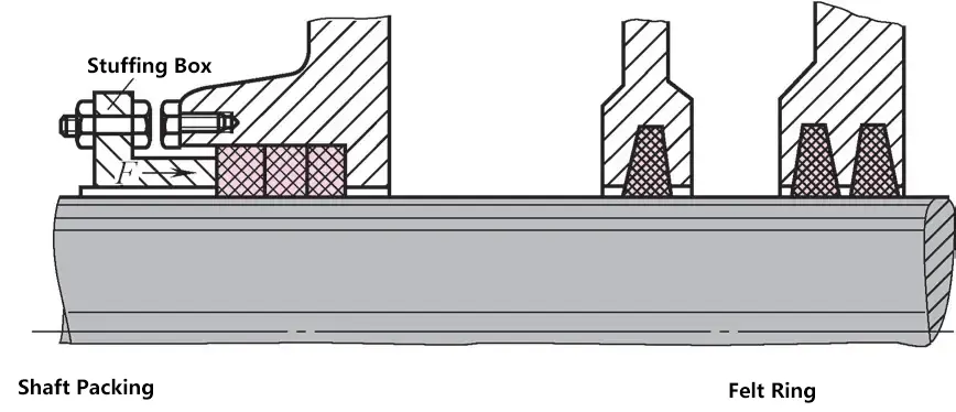
(2) Felt rings
Used to seal bearing oil chambers. They are simple to manufacture and inexpensive.
(3) O-ring seals
Used for pistons and piston rods with low working pressure.
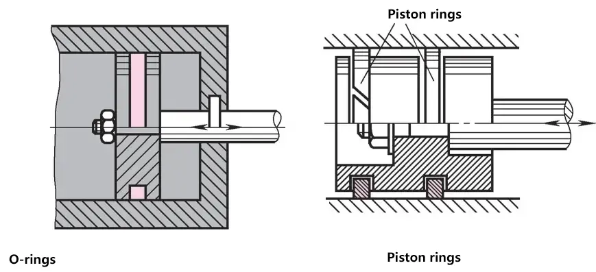
(4) Piston rings
Made of gray cast iron or non-ferrous metals, they can effectively seal high-pressure pistons and have good wear resistance.
2. Non-contact Sealing
(1) Clearance sealing
Uses the small clearance between moving parts to provide sealing action, which can prevent dust and dirt from entering to some extent, but cannot prevent the outflow of liquids and gases.
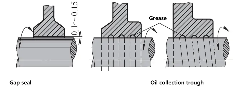
(2) Oil groove
Should be filled with grease during assembly. When the shaft rotates at high speed, vortices form in the oil groove, creating an effective seal.
(3) Labyrinth seal
Filled with grease, it is an excellent seal for preventing dust entry and oil leakage. The clearance is 0.5-0.75mm.
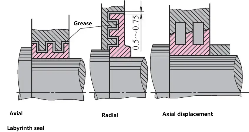
(4) Labyrinth
Axial labyrinth is used for split bearings, while radial labyrinth is used for integral bearings.
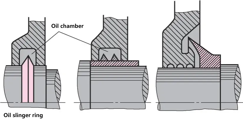
(5) Oil splash ring
Oil flowing on the shaft splashes out at its maximum circumference (at maximum circumferential speed). The splashed oil returns to the casing through holes in the lower part of the oil chamber.
IV. Bearings
1. Sliding bearings
The function of bearings is to support the shaft and parts on the shaft, allowing them to rotate and maintain a certain rotational precision, reducing friction and wear between relatively rotating parts.
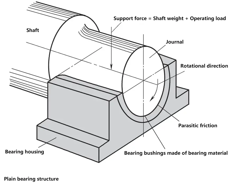
(1) Friction and lubrication
1) Dry friction
Although the surface of the journal is ground and the inner surface of the bearing is precision machined, there is still a certain roughness. Without lubricant, there would be significant sliding friction between these surfaces, resulting in high temperatures and wear. Dry friction is not allowed in practical use.

2) Mixed friction
After adding lubricant to the sliding surfaces, the protrusions on the metal surfaces still contact each other, causing minor friction and wear. This is not acceptable for shafts working for long periods.
Mixed friction mainly occurs when the journal starts to rotate. Bearings that frequently alternate between stationary and rotating states wear faster than those in continuous operation.
3) Fluid friction
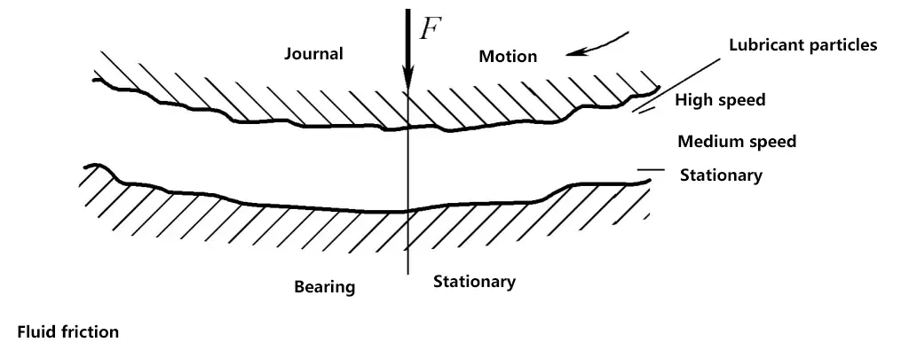
If there is sufficient lubricating oil between the two friction surfaces and certain conditions are met, a pressure oil film with a thickness of several tens of microns can form between the two friction surfaces. It can separate the two moving metal surfaces. In this case, there is only friction between the fluids.
4) Position of the journal in the bearing
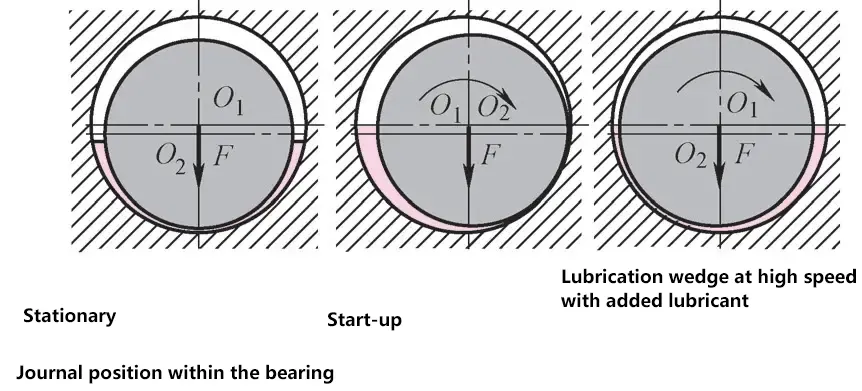
The wedge-shaped oil film produced at maximum rotation speed must not be interrupted.
5) Forces in the lubricant
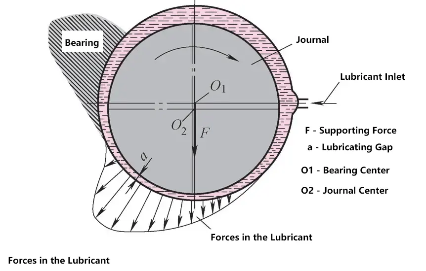
F—Supporting force
a—Lubrication gap
O₁—Bearing center
O₂—Journal center
In the case where the journal and bearing surface do not contact, the lubricant must transfer the entire supporting force from the journal to the bearing. The lubricant is in a stressed state
.
The lubricant should have a certain viscosity to ensure it is not squeezed out from the bearing ends. High-viscosity lubricants are suitable for bearings with high supporting force, low speed, and high temperature; low-viscosity lubricants are suitable for bearings with low supporting force, high speed, and low temperature.
Viscosity is the property of a liquid that produces internal friction between its molecules when flowing.
6) Oil grooves on the bearing bush

To introduce lubricating oil into the bearing, oil supply holes and grooves are often made on it; oil supply holes and grooves should be placed in the non-load-bearing area of the bearing bush, otherwise, they will reduce the load-bearing capacity of the oil film. Axial oil grooves should not be opened along the entire length of the bearing bush to prevent lubricating oil from leaking from the ends of the oil groove.
(2) Types of bearings
Sliding bearings can be classified into radial bearings and thrust bearings according to the direction of force.
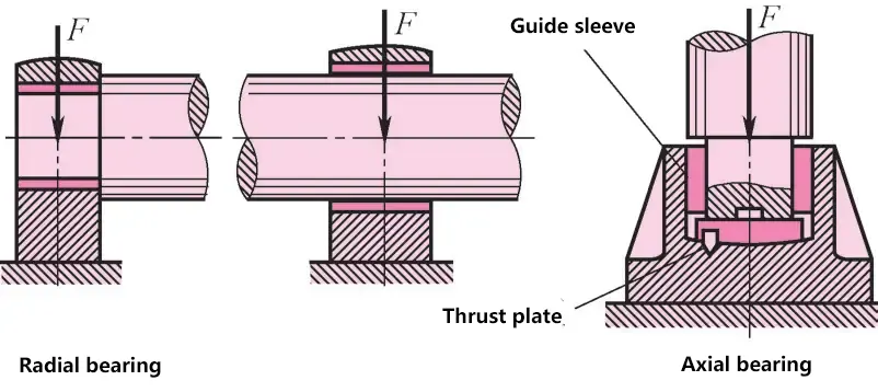
Radial bearings bear radial forces and support positions in the middle or end of the shaft; thrust bearings generally support vertically placed shafts and are also called thrust bearings.
1) Sleeve bearings
A cast or welded sleeve with a bushing made of bearing material.
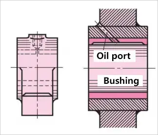
2) Integral bearings
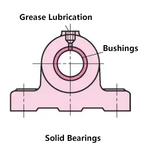
Generally cast from gray cast iron. The bushing is made of bearing material and uses a press fit.
3) Split sliding bearings
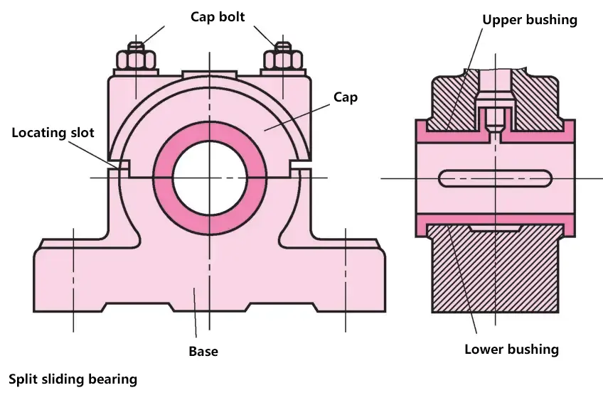
Composed of a base, upper cover, bearing bush, and bolt assembly. This type of bearing can be made with or without a bearing bush. Its features include easy installation and removal, and the radial clearance of the bearing can be adjusted after wear, making it widely used.
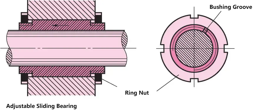
4) Adjustable sliding bearings
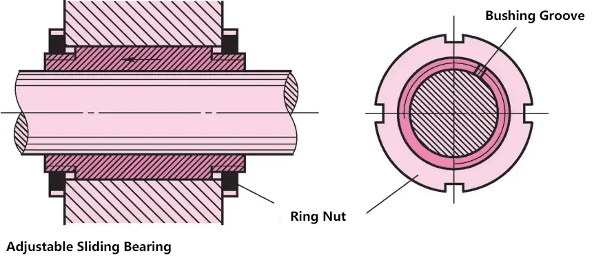
Some sliding bearings, such as lathe spindle bearings, should have a stable bearing clearance. After long-term operation, when the clearance becomes too large due to wear, adjustment is needed. The slotted bushing is tightened in the tapered hole with a left-hand nut, reducing the bore diameter of the bushing. During installation, care should be taken not to make the bearing clearance too small, which could cause overheating during operation.
(3) Bearing materials
Even with good lubrication, there is still brief metal contact between the sliding bearing surface and the journal. To reduce wear and prevent seizing of the bearing surface, certain requirements are placed on the materials for shaft linings and bearing bushes. They should be wear-resistant, corrosion-resistant, pressure-resistant, have low thermal expansion, and good thermal conductivity when heated.
1) Bearing alloys
Bearing alloys are alloys of tin, lead, antimony, and copper, with tin or lead as the matrix, containing hard crystals of antimony-tin (Sb-Sn) or copper-tin (Cu-Sn). The hard crystals provide wear resistance, while the soft matrix increases the material’s plasticity.
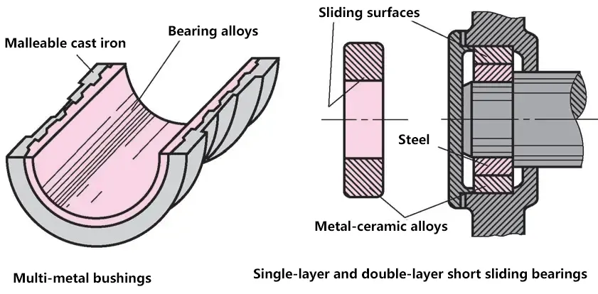
Bearing alloys have very low strength and cannot be used alone to make bearing bushes; they can only be adhered to bronze, steel, or cast iron bearing bushes as bearing linings. Bearing alloys are suitable for heavy-load, medium to high-speed applications and are relatively expensive.
2) Copper alloys
Copper alloys have relatively high strength, good friction reduction, and wear resistance. Bronze has better friction reduction and wear resistance than brass, making it the most commonly used material. There are several types of bronze, including tin bronze, lead bronze, and aluminum bronze.
Tin bronze has the best friction reduction and wear resistance, is widely used, and is suitable for heavy-load and medium-speed applications. Lead bronze has strong anti-seizing ability and is suitable for high-speed, heavy-load bearings.
Aluminum bronze has higher strength and hardness but poorer anti-seizing ability, making it suitable for low-speed, heavy-load bearings.
3) Aluminum-based bearing alloys
Aluminum-based bearing alloys have gained widespread use in many countries. They have quite good corrosion resistance, relatively high fatigue strength, and good friction reduction properties. Aluminum-based bearing alloys can be made into single-metal parts (such as bushings, bearings, etc.) or bi-metal parts, where the bi-metal bearing bush uses aluminum-based bearing alloy as the bearing lining and steel as the backing.
4) Gray cast iron and wear-resistant cast iron
Ordinary gray cast iron or wear-resistant gray cast iron with added alloy elements such as nickel, chromium, and titanium, as well as nodular cast iron, can all be used as bearing materials.
The flake or spheroidal graphite in these materials can form a lubricating graphite layer on the material surface, thus providing some friction reduction and wear resistance. Cast iron is brittle and has poor running-in performance, so it is only suitable for light-load, low-speed applications and situations without impact loads.
5) Non-metallic materials
Among non-metallic materials, various plastics are most widely used, such as phenolic resin, nylon, and polytetrafluoroethylene. The characteristics of polymers are: they do not react with many chemical substances and have good corrosion resistance.
(4) Lubricant supply
The main methods of lubricant supply include oil cup drip lubrication, oil ring lubrication, and centralized lubrication.
1) Oil cup drip lubrication
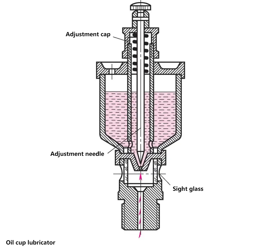
When the handle is placed in a vertical position, the needle valve rises, opening the oil hole for oil supply; when the handle is placed horizontally, the needle valve returns to its original position, stopping the oil supply. Turning the adjusting nut can regulate the amount of oil supplied.
2) Oil ring lubrication
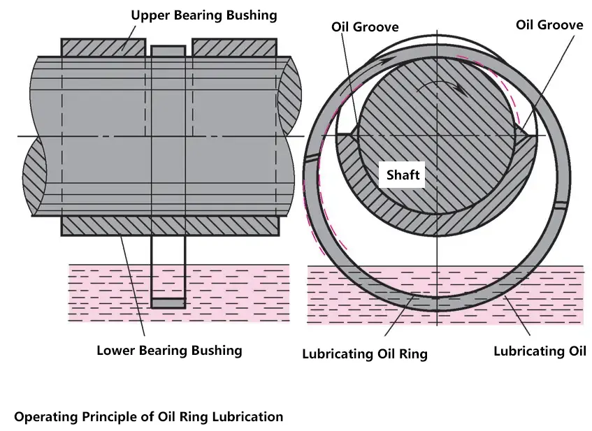
The oil ring is fitted over the journal and hangs into the oil reservoir. When the shaft rotates, it drives the oil ring to rotate by friction, bringing lubricating oil to the journal for lubrication. This lubrication method has a simple structure, but since it relies on friction to drive the oil ring to splash oil, sufficient oil supply is only possible when the shaft speed is appropriate.
(5) Bearing installation and maintenance
Before installation, the dimensions of the journal and bearing bore should be checked.
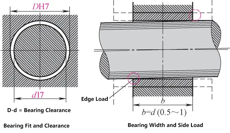
Bearings use various clearance fits according to the required rotational precision. The bearing width is very important; in bearings that are too wide, even a small shaft misalignment can produce very harmful edge side pressure.
1) Bushing installation
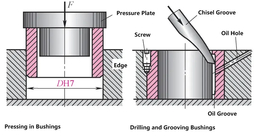
Generally, a light press fit is used, or a tight transition fit can be used when installation conditions are poor. When installing the bushing, it should be accurately perpendicular to the bearing end face. After installation, check the bore size; an overly tight fit will compress the bushing, and reaming may be necessary. For bushings with transition fits, holes can be drilled and a screw inserted to prevent loosening or rotation.
2) Bearing bush installation
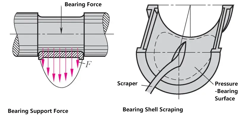
High-precision bearings may require scraping. Apply color to the journal, fit the bearing, tighten the bolts. Rotate the journal a few times, possibly under some load, then open the bearing and scrape the contact points until the bearing bush only contacts in the middle part. This way, the middle part of the bearing bush bears the most weight.
3) Sliding bearing maintenance
If a bearing becomes heated, there is a risk of high-temperature operation. This phenomenon may be caused by: incorrect lubricant use, interrupted oil supply, shaft bending causing edge side pressure, poor alignment of bearing centerlines, bearing clearance too small, incorrect bearing material, or excessive supporting force.
2. Rolling bearings
By introducing rolling elements between moving objects and friction surfaces, friction force is reduced, and the force needed to overcome friction is also reduced. Theoretically, the contact between spherical rolling elements and friction surfaces should only be point contact.
In reality, due to the acting force flattening the spherical rolling elements and pressing them into the friction surfaces, it becomes surface contact, which increases friction.
(1) Structure of rolling bearings
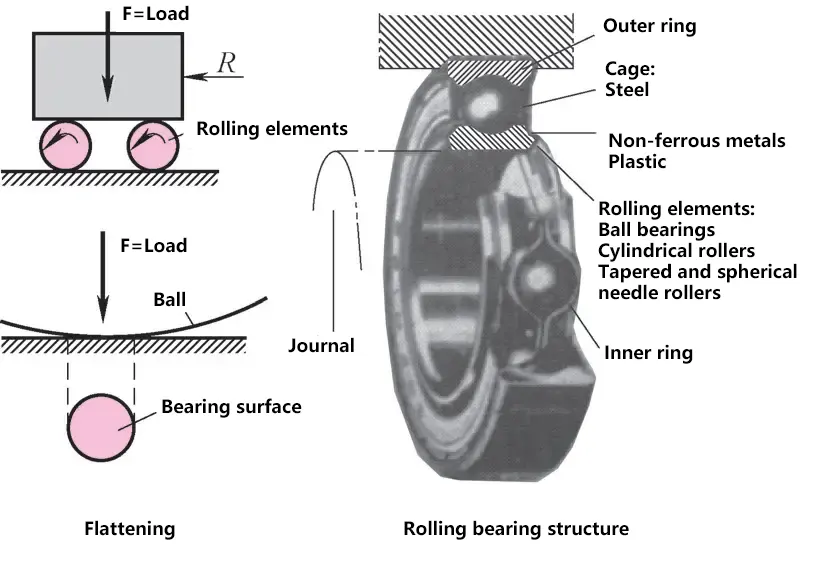
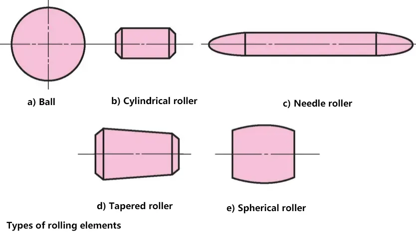
Rolling bearings rely on rolling contact between main components to support rotating parts, meaning the friction nature is rolling friction.
It mainly consists of four parts: inner ring, outer ring, rolling elements, and cage. Only needle roller bearings do not have an inner ring. The outer ring is the connecting piece between the bearing and the bearing housing, and also the outer raceway for the rolling elements. The inner ring is the connecting piece between the bearing and the journal, and also the inner raceway. Rolling elements include balls, cylindrical rollers, needle rollers, tapered rollers, and spherical rollers, whose positions are maintained by the cage.
Rolling bearings have advantages such as low friction resistance, easy startup, high efficiency, and small axial dimensions. Moreover, due to large-scale standardized production, they have the advantage of low manufacturing costs, thus being widely used in various machines.
(2) Types of rolling bearings
Many rolling bearings transmit both radial and axial forces simultaneously. The selection of rolling bearings is based on the magnitude and direction of the force.
Rolling bearings are classified according to the load direction and the type of rolling elements.
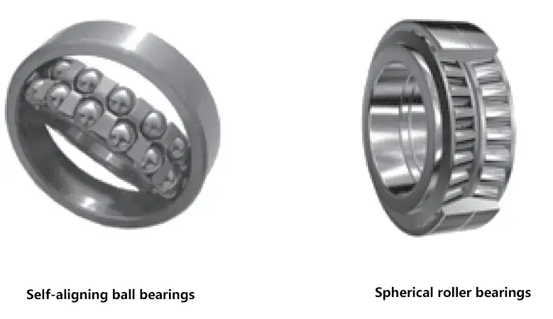
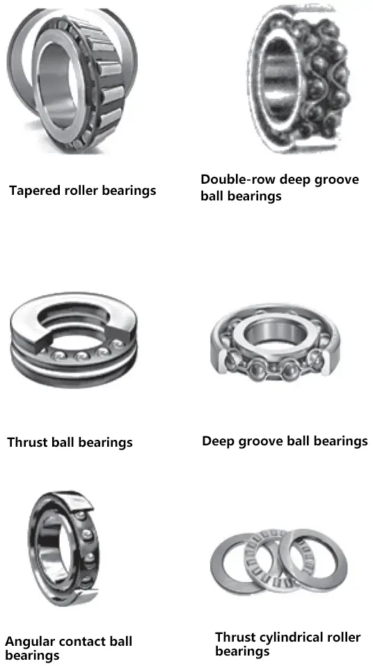
Types of rolling bearings
| Bearing name | Basic characteristics |
| Self-aligning ball bearings | Mainly bear radial loads, can also bear small bi-directional axial loads |
| Self-aligning roller bearings | Mainly used to bear radial loads, can also bear small bi-directional axial loads. Suitable for heavy load and impact load conditions |
| Tapered roller bearings | Can simultaneously bear large radial loads and unidirectional axial loads. Inner and outer rings can be separated, usually used in pairs, installed symmetrically |
| Double row deep groove ball bearings | Mainly bear radial loads, can also bear certain bi-directional axial loads |
| Thrust ball bearings | Can only bear unidirectional axial loads, suitable for situations with large axial loads and low speeds |
| Deep groove ball bearings | Mainly bear radial loads, can also simultaneously bear small bi-directional axial loads. Low friction resistance, high limit speed, simple structure, inexpensive, most widely used |
| Angular contact ball bearings | Can simultaneously withstand radial and axial loads, with nominal contact angles α of 15°, 25°, and 40°. The larger the contact angle, the greater the ability to withstand axial loads, suitable for situations with relatively high speeds and simultaneous radial and axial loads. |
| Thrust cylindrical roller bearing | Can withstand very large unidirectional axial loads. Load capacity is much greater than thrust ball bearings, but angular misalignment is not allowed. |
(3) Rolling bearing codes
The code for rolling bearings consists of three parts: prefix code, basic code, and suffix code.
Rolling bearing codes
| Prefix code | Basic code | Suffix code | ||||
| Five | Four | Three | Two | One | ||
| Bearing component code | Type code | Dimension series code | Bore code | Supplementary code for bearing structure, shape, dimensions, tolerances, and technical requirements | ||
| Width (height) series code | Diameter series code | |||||
1) Basic code
The basic code is the fundamental part that represents the main characteristics of the bearing, including bearing type, dimension series, and bore.
① Type code.
The bearing type code is represented by numbers or letters.
Bearing type code
| Type code | Bearing type |
| 0 | Double-row angular contact ball bearing |
| 1 | Self-aligning ball bearing |
| 2 | Spherical roller bearing and thrust spherical roller bearing |
| 3 | Tapered roller bearing |
| 4 | Double-row deep groove ball bearing |
| 5 | Thrust ball bearing |
| 6 | Deep groove ball bearing |
| 7 | Angular contact ball bearing |
| 8 | Thrust cylindrical roller bearing |
| N | Cylindrical roller bearing (NN: double-row or multi-row) |
| U | Spherical plain bearing |
| QJ | Four-point contact ball bearing |
② Dimension series code.
The dimension series code is a combination of the bearing’s diameter series code and width (height) series code, represented by two digits.

The width series refers to radial bearings or thrust bearings with the same structure, bore, and diameter, but a series of different widths (heights). For radial bearings, the width code increases in the order of 8, 0, 1, …, 6, while for thrust bearings, the height code follows the order 7, 9, 1, 2. When the width series is 0, it can be omitted from the code for most bearings.
The diameter series represents the variation series in outer diameter and width for bearings of the same type and bore, indicated by the third digit from the right in the basic code. The outer diameter size increases in the order of 7, 8, 9, 0, 1, …, 5.
③ Bore code.
The bore code uses two digits to represent the bearing’s bore: for bearings with bore d=10~480mm, the bore representation method is shown in the table on the right. For bearings with other dimensions, refer to relevant manuals and standards.
Bore code
| Bore code | 00 | 01 | 02 | 03 | 04~96 (except 22, 28, 32) |
| Bearing bore/mm | 10 | 12 | 15 | 17 | Code number × 5 |
2) Prefix code, suffix code
Prefix and suffix codes are supplementary codes added to the left and right of the basic code when there are changes in the bearing’s structure, shape, dimensions, tolerances, and technical requirements.
The prefix code is represented by letters and is used to describe the characteristics of complete bearing assemblies. For general bearings that do not require this description, the prefix code can be omitted.
The suffix code uses combinations of letters and letter-number combinations. It can be placed immediately after the basic code or separated by “-” or “/” symbols, depending on different situations. Its meaning can be found in relevant standards.
(4) Selection of rolling bearings
There are many types of rolling bearings, so the first step in selecting a rolling bearing is choosing the type. The selection of type must be based on the characteristics of each bearing type. When selecting rolling bearings, the following factors should also be considered.
1) Applied load
For pure radial loads, radial bearings should be selected. For pure axial loads, thrust bearings should be chosen. For bearings that simultaneously bear radial and axial loads, consider using radial-thrust bearings or a combination of radial and thrust bearings to separately bear radial and axial loads.
2) Rotational speed
At general speeds, the level of speed does not affect type selection. Only when the speed is relatively high does it have a significant impact. Ball bearings are usually chosen for high-speed applications.
3) Self-aligning performance requirements
For shafts with low rigidity due to large support spans, or when shaft deflection occurs due to low concentricity of bearing housing bores, self-aligning bearings that allow for larger relative misalignment between inner and outer rings should be selected to accommodate shaft deformation.
4) Ease of assembly and other factors
When selecting bearing types, factors such as ease of assembly and disassembly, installation space limitations, and economic considerations should also be taken into account. For example, when radial dimensions are restricted, bearings of the same type and bore with smaller middle and outer diameters should be selected, or needle roller bearings should be considered.
Ball bearings are cheaper than roller bearings and should be prioritized when they can meet the requirements. There is a significant price difference between bearings of the same model with different tolerance grades, so high-precision bearings should be selected carefully.
(5) Installation and removal of rolling bearings
1) Installation
Rolling bearings should be kept in their original packaging and cleaned only when being installed. When installing rolling bearings, it is important to ensure that the force applied to the outer ring is not transmitted to the inner ring through the rolling elements, and vice versa.
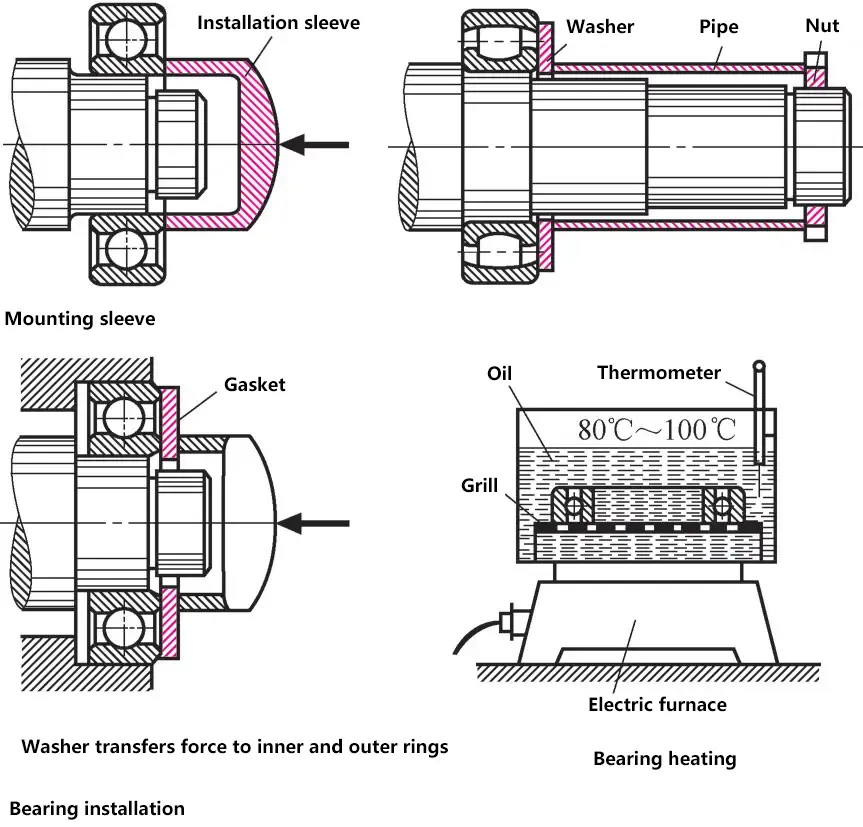
Otherwise, damage to the rolling elements and raceways is inevitable. When fitting onto a shaft, use an installation sleeve that only contacts the inner ring. If the bearing is far from the shaft end, use a sleeve that is flat on both ends.
For tight fits, heat the bearing in an oil bath or electric furnace to 100°C (turning frequently). Higher temperatures may cause structural changes in heat-treated bearing components.
When installing bearings with a tight fit sleeve or in a tapered fit, the bearing clearance should be checked frequently, as the expansion of the inner ring will reduce the bearing clearance. The clearance of non-separable bearings is checked using a feeler gauge.
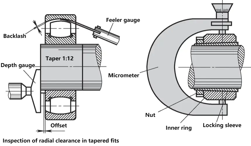
For separable bearings, a micrometer is used to measure the expansion of the inner ring. Empirical formula: The ratio of axial displacement to bearing clearance reduction is 15:1, meaning for every 1mm of axial displacement, the bearing clearance reduces by 1mm/15=0.06mm.
2) Disassembly
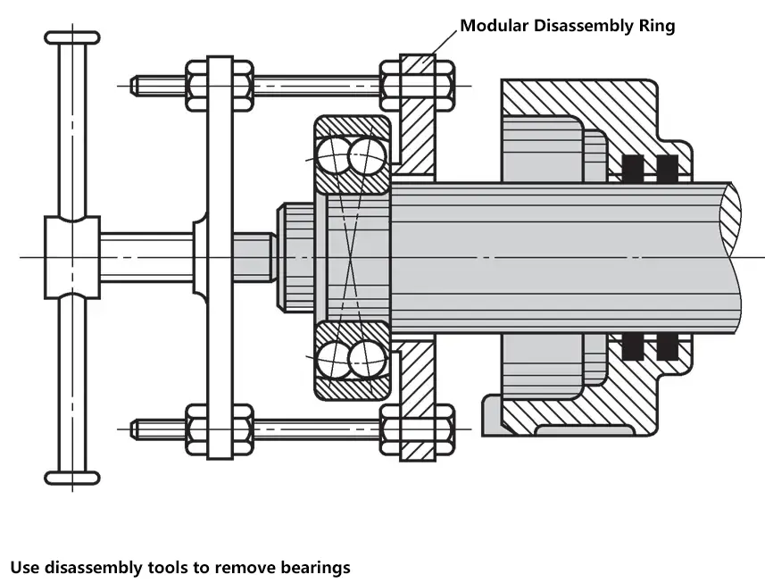
When disassembling, care should be taken not to transmit the loosening force through the rolling elements. It’s best to use disassembly tools. When removing the inner ring of a large tight-fit bearing, wrapping the inner ring with an oil-soaked cloth or heating it with steam can make the disassembly easier. Do not use a blowtorch or welding nozzle for heating.
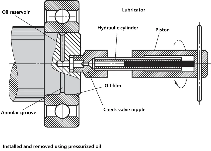
Installation and removal using high-pressure oil: Use a small manual hydraulic press or oil injector to inject oil pressure into the gap between the bearing ring and shaft, forming an oil film that can reduce static friction, making the bearing ring easier to install or remove.
3) Lubrication and Maintenance
Only specified lubricating oil should be used, and the lubricant should be selected based on bearing size, speed, load, operating temperature, and sealing. The lubricant filling amount should be half of the bearing clearance. The oil level should reach half the height of the rolling elements. Disassembly, cleaning, and lubricant replacement for rolling bearings are generally carried out after one year of operation.
V. Couplings and Clutches
1. Couplings
Couplings are used to connect two shafts on different mechanisms or components to transmit motion and torque, and remain connected during operation. The two shafts connected by a coupling can only be separated after the machine has stopped working and been disassembled.
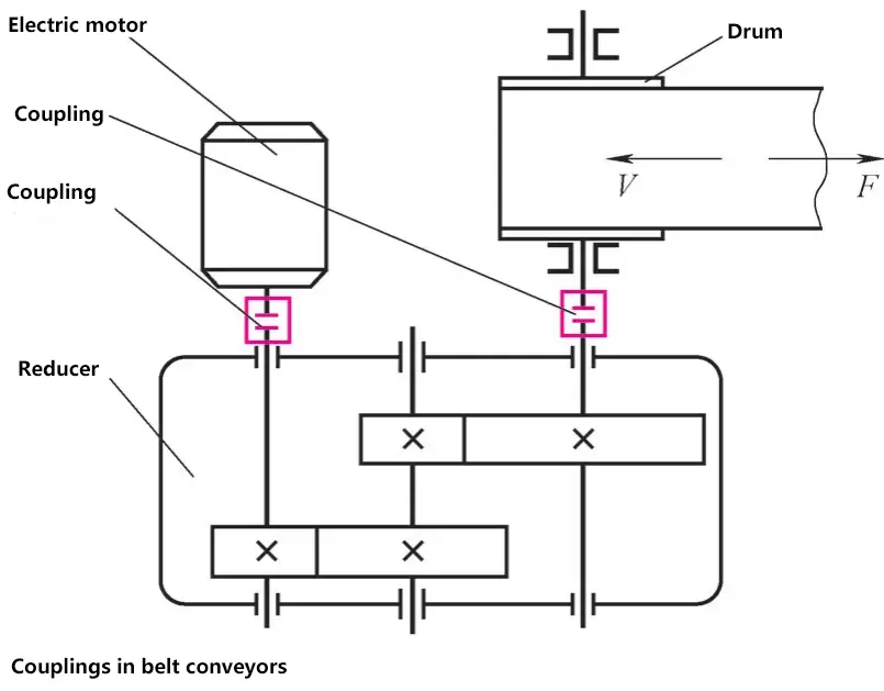
(1) Rigid Couplings
Rigid couplings are composed of rigid power transmission elements, have no cushioning properties, but can transmit larger torques. They are further divided into fixed rigid couplings and movable rigid couplings.
1) Fixed Rigid Couplings.
① Sleeve coupling.
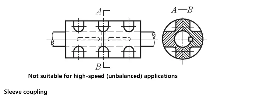
The sleeve position is fixed with a key, used for small torque and low-speed situations. The advantage is that it can be installed on shafts that are already in place.
② Flange coupling.
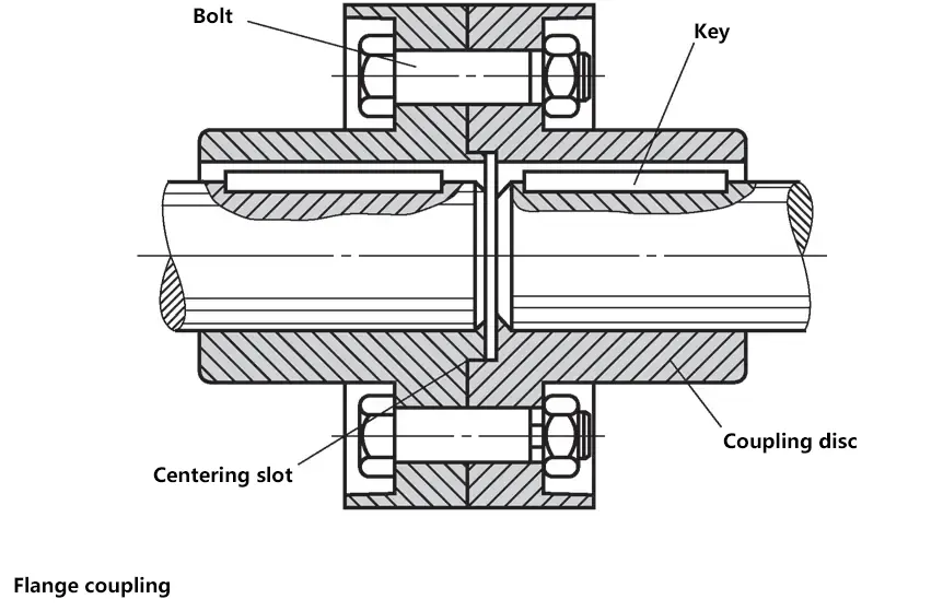
Installed using bolts, torque is transmitted through key connections. To avoid imbalance, bolts should be tightened symmetrically. A certain gap should be maintained between shafts during installation. Its structure is simple, operation reliable, rigidity good, easy to use and maintain, and can transmit large torques, but it has higher requirements for shaft alignment.
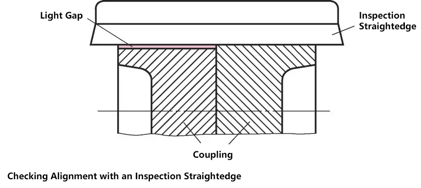
Installation of rigid couplings: Before tightening the coupling, the shaft journals must be aligned to meet the concentricity requirements of the shaft centers. The installation accuracy is checked by examining the light gap on the flange circumference using a checking ruler.
2) Movable Rigid Couplings.
① Universal joint coupling.
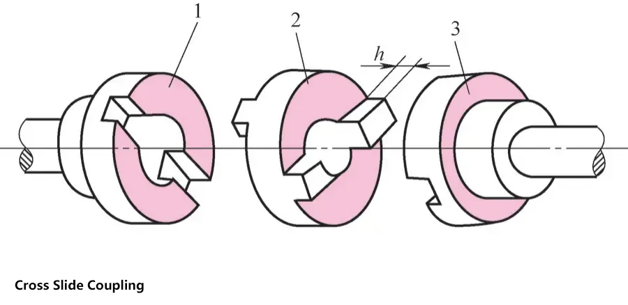
Simple structure, easy to manufacture, can accommodate composite offsets between two shafts. Suitable for various applications such as tachometers, encoders, machine tools, etc.
② Gear coupling.
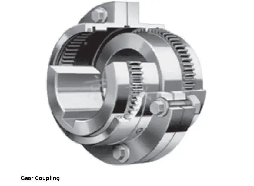
Compared to universal joint couplings, gear couplings have higher speeds, and because multiple teeth are engaged simultaneously, they are more reliable and have greater load-bearing capacity, but manufacturing costs are higher. They are generally used in heavy machinery with frequent starts and frequent forward and reverse rotations.
③ Universal coupling.
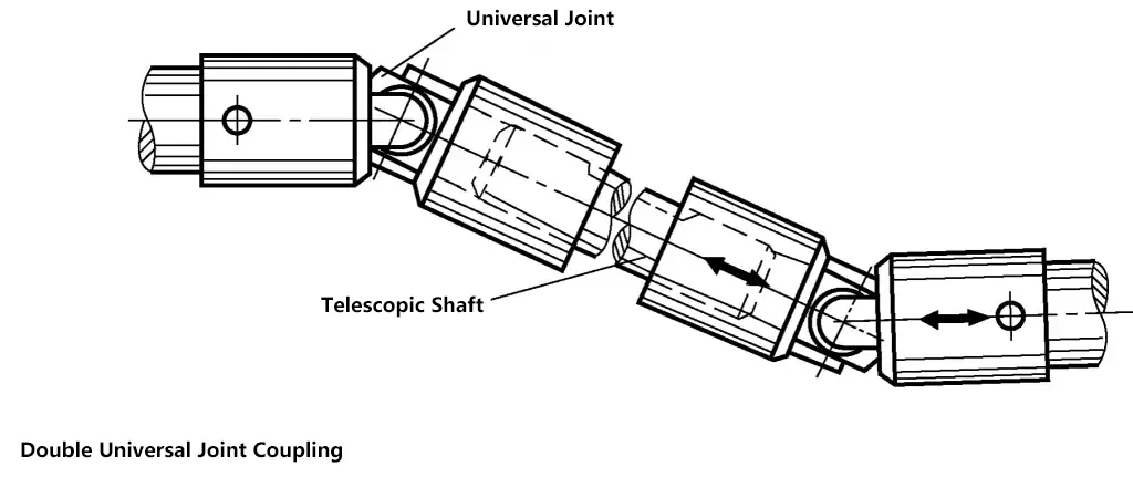
Universal couplings have a compact structure, are easy to maintain, and are widely used in automobiles, multi-spindle drilling machines, and other machines.
(2) Flexible Couplings
Flexible couplings contain elastic elements, thus providing cushioning and vibration reduction effects. The small deformation of the elastic elements can compensate for the relative displacement of the two shafts, giving them movability. Common types include elastic sleeve pin couplings, elastic pin couplings, and tire couplings.
1) Elastic sleeve pin coupling.
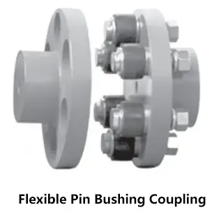
Similar to flange couplings, elastic sleeve pin couplings use pins with non-metallic (such as rubber) elastic sleeves instead of bolts. Elastic sleeve pin couplings have a simple structure, are easy to assemble and disassemble, and have a relatively low cost.
They rely on the elasticity of the elastic sleeve for cushioning, vibration reduction, and compensation for shaft misalignment. They are commonly used to connect high and medium-speed shafts with relatively stable loads, requiring forward and reverse rotation or frequent starts, and transmitting medium to small torques, such as various rotary pumps.
2) Elastic pin coupling.
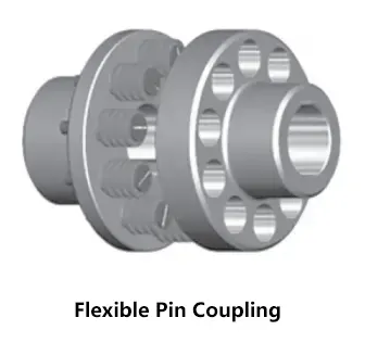
The elastic element is a pin made of nylon material. Compared to elastic sleeve pin couplings, it has a greater ability to transmit torque, a simpler structure, is easier to manufacture, more convenient to replace, and the pins have better wear resistance.
Widely used in situations with moderate speeds, forward and reverse rotations or frequent starts, and low cushioning requirements, such as in the paper, metallurgy, mining, lifting and transportation, petrochemical industries, etc.
3) Tire coupling.
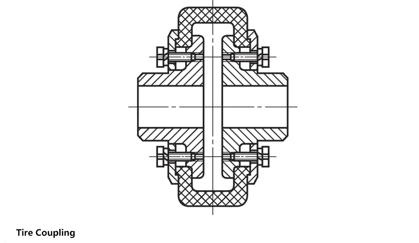
Simple structure, reliable operation, good comprehensive performance, and ability to compensate for displacement and absorb vibrations; radial dimensions are relatively large, and when the torque is large, excessive torsional deformation may produce additional axial loads.
Suitable for situations with frequent starts, shock and vibration, as well as humid, dusty environments with large relative displacements, such as common electric motors, ordinary reducers, vibrating machinery, impact machinery, and other working conditions.
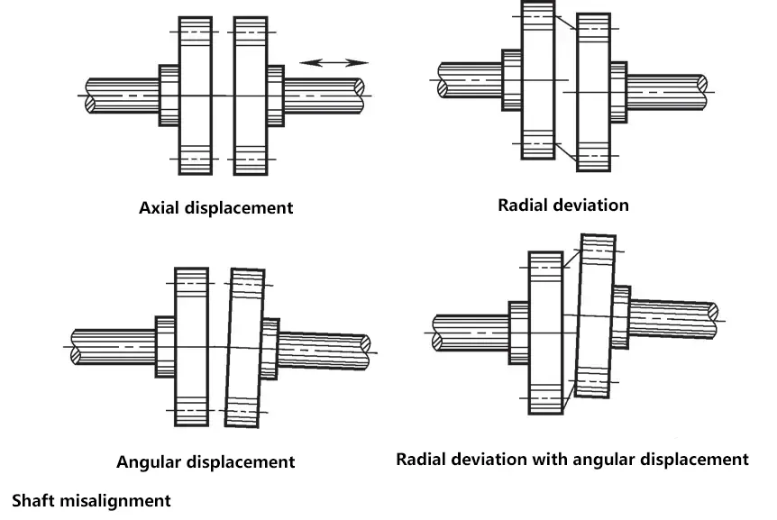
(3) Mobility of Couplings
Due to manufacturing and installation errors, elastic deformation of components under load, and thermal expansion differences, relative misalignment between the two shafts connected by a coupling is inevitable.
The occurrence of relative misalignment between the two shafts will cause additional loads on the shafts, bearings, and couplings, and may even result in severe vibrations. To reduce vibrations in the mechanical transmission system and lower peak impact loads, couplings should also have certain cushioning and vibration reduction properties.
(4) Selection of Couplings
Based on the working conditions and usage requirements of the machine equipment, first select the type of coupling, then determine the model of the coupling according to the shaft end diameter, torque magnitude, rotation speed, spatial dimensions, and other requirements.
Rigid and Flexible Couplings
| Rigid Couplings | Flexible Couplings | |
| Simple structure, large torque transmission, long lifespan, sensitive to impact loads | 1) Have cushioning and vibration reduction properties, suitable for frequent starts and reversals 2) Elastic elements are relatively weak, not suitable for transmitting large torques, shorter lifespan 3) Can compensate for relative displacement between two shafts | |
| Fixed type | Movable type | |
| Requires high installation accuracy and high shaft rigidity | Can accommodate installation errors between two shafts to varying degrees | |
2. Clutches
Clutches are mainly used in machines to connect two shafts on different mechanisms or components to transmit motion and torque, and can separate or connect the two shafts at any time during operation.
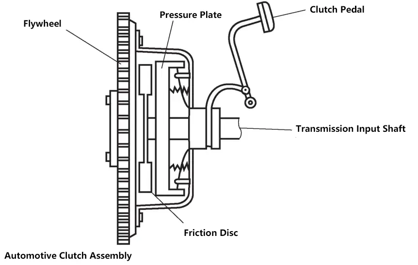
(1) Types of Clutches
Based on different working principles, clutches have types such as tooth engagement and friction types, which respectively use tooth engagement and friction between contact surfaces to transmit torque.
1) Tooth engagement clutch.
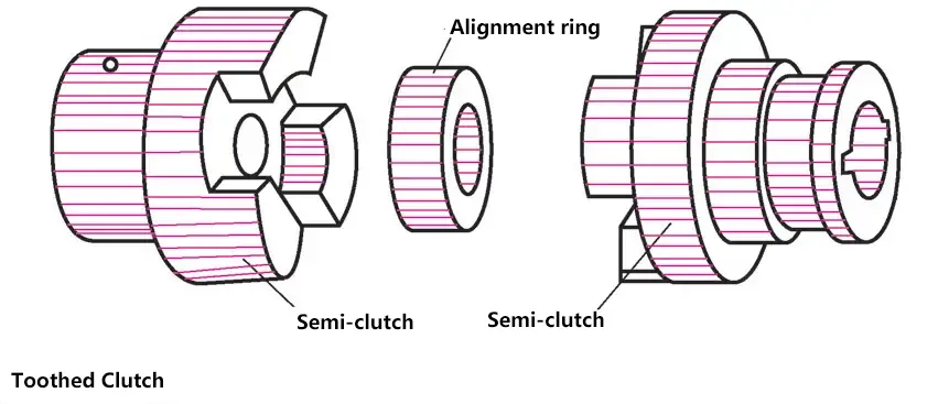
Simple and compact structure, small overall dimensions; no relative sliding between the two halves of the clutch when engaged, thus no heat generation. Suitable for high-precision machine tools requiring strict synchronization between driving and driven shafts, but can only be engaged at low speeds or when stopped to avoid breaking teeth due to impact.
2) Single-plate friction clutch.
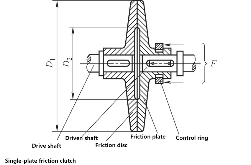
Uses the tightening or loosening of two friction discs to create or eliminate friction force between the two mating surfaces, achieving engagement or disengagement of the two shafts. Its structure is simple, disengagement is complete, but radial dimensions are relatively large. Suitable for light machinery transmitting small torques.
3) Multi-plate friction clutch.
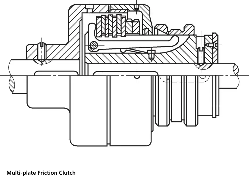
Multi-plate friction clutches have more friction surfaces, significantly increasing torque transmission, relatively reducing radial dimensions, but with a more complex structure. Suitable for situations requiring transmission of larger torques.
(2) Selection of Clutches
Most clutches have been standardized or specified, so during design, one only needs to refer to relevant design manuals for comparative design or selection. When selecting a clutch, there are several requirements:
- Determine the type of clutch based on the machine’s working characteristics and operating conditions, combined with the performance characteristics of various clutches.
- Once the type is determined, select an appropriate model from relevant design manuals based on the diameters of the two shafts to be connected, calculated torque, and rotation speed.
- If necessary, perform load-bearing capacity checks on its weak links.
VI. Gear Transmission
Two or more gears working together are called a gear transmission mechanism.
1. Types of Gears
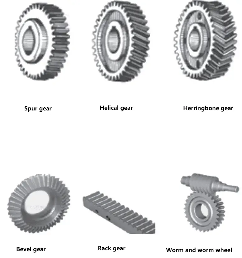
1) Gears can be classified by tooth profile into involute gears, cycloidal gears, circular arc gears, etc. Involute gears are easy to manufacture and widely used, while cycloidal gears and circular arc gears are less common.
2) Gears are classified by shape into cylindrical gears, bevel gears, rack and pinion, and worm gear transmissions.
2. Dimensions of Spur Cylindrical Gears
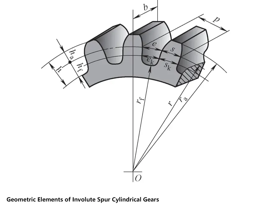
(1) Names and geometric dimensions of various parts of spur cylindrical gears
Names of various parts of standard spur cylindrical gears
| Name | Symbol | Definition |
| End plane | The surface perpendicular to the gear axis on a cylindrical gear | |
| Addendum circle radius | ra | The intersection line of the addendum cylinder surface with the end plane |
| Dedendum circle radius | rf | The intersection line of the dedendum cylinder surface with the end plane |
| Pitch circle radius | r | The intersection line of the pitch cylinder surface with the end plane |
| Tooth thickness | s | The arc length on the pitch circle between the two side faces of a tooth on the end plane |
| Space width | ext: e | The arc length on the pitch circle between the two tooth profiles of a tooth space on the end plane |
| Circular pitch | p | The arc length on the pitch circle between two adjacent and same-side end face tooth profiles |
| Addendum | ha | The radial distance between the addendum circle and the pitch circle |
| Dedendum | hf | The radial distance between the dedendum circle and the pitch circle |
| Whole depth | h | The radial distance between the addendum circle and the dedendum circle |
| Face width | b | The width of the toothed portion of the gear measured along the straight generatrix of the pitch cylinder surface |
| Center distance | a | The shortest distance between the two axial lines of a pair of meshing gears |
(2) Main parameters of spur cylindrical gears
1) Number of teeth z.
The total number of teeth on a gear, denoted by z. When the module is fixed, the more teeth, the larger the geometric dimensions of the gear.
2) Module m.
The quotient of the tooth pitch p and pi is called the module, denoted by m, i.e., m=p/π, with the unit of mm. The module is the basic parameter of gears. With the same number of teeth, the larger the module, the larger the gear size and the stronger the load-bearing capacity. For gears with equal pitch circle diameters, the larger the module, the stronger the load-bearing capacity.
Standard module series (unit: mm)
| First series | 1,1.125,1.375,1.25,1.5,2,2.5,3,4,5,6,8,10,12,16,20,25,32,40,50 |
| Second series | 1.75, 2.25, 2.75, 3.5, 4.5, 5.5, (6.5), 7, 9, (11), 14, 18, 22, 28, 36, 45 |
Note: 1. The standard applies to involute cylindrical gears. For helical gears, it refers to the normal module.
2. When selecting a module, priority should be given to the first series.
3) Pressure angle.
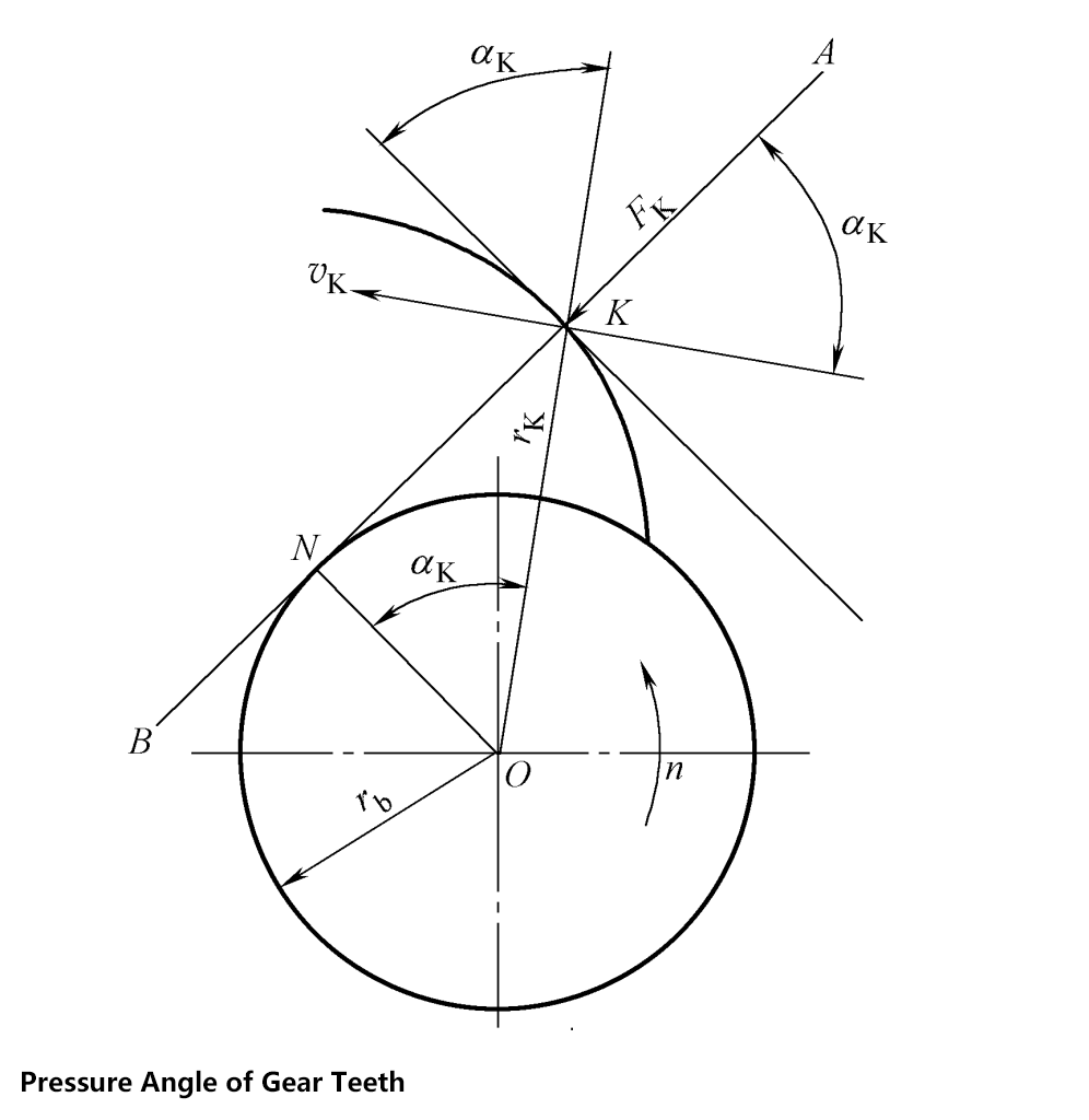
The pressure angle is the acute angle between the radial line passing through any point K on the end face tooth profile and the tangent line at that point on the tooth profile in the end plane of the gear. It is also the acute angle between the velocity direction at the intersection point of the tooth profile curve and the pitch circle and the normal direction at that point (i.e., the direction of force action) in gear transmission, called the pitch circle pressure angle.
Pressure angle αk on the pitch circle of involute cylindrical gears
cosak = rb/ r
Where
- ak – pressure angle (°);
- rb – base circle radius (mm);
- r – pitch circle radius (mm).
Chinese standards specify that the pressure angle α on the pitch circle of involute cylindrical gears is 20°.
4) Addendum coefficient.
The ratio of addendum to module is called the addendum coefficient, denoted by h a * , i.e., h a = h a * m, standard h a * = 1.
5) Clearance coefficient.
When a pair of gears mesh, to allow the tooth top of one gear to connect with the bottom of the tooth space of the other gear, the dedendum should be greater than the addendum, i.e., there should be a certain radial clearance, called top clearance, denoted by c.
The ratio of top clearance to module is called the clearance coefficient, denoted by c * . The top clearance c = c * m. National standards specify: the standard gear c * = 0.25.
(3) Calculation of geometric dimensions of standard spur cylindrical gears
Standard spur cylindrical gears use standard module m, pressure angle α = 20°, addendum coefficient h a * = 1, clearance coefficient c * = 0.25.
Geometric dimensions of standard spur cylindrical gears
| Name | Symbol | Calculation formula | |
| External gear | Internal gear | ||
| Pressure angle | α | 20° for standard gears | |
| Number of teeth | z | Determined by calculating the transmission ratio | |
| Module | m | Determined by calculation or structural design | |
| Tooth thickness | s | s = p/2 = πm/2 | |
| Tooth space width | ext: e | e = p/2 = πm/2 | |
| Circular pitch | p | p = πm | |
| Base pitch | Pb | p b = pcosα = πmcosα | |
| Addendum | ha | ha = ha * = m | |
| Dedendum | hf | hf = (ha * + c * )m = 1.25m | |
| Whole depth | h | h = ha + hf = 2.25m | |
| Pitch circle diameter | d | d = mz | |
| Addendum circle diameter | da | da = d + 2ha = m(z + 2) | da = d – 2ha = m(z – 2) |
| Dedendum circle diameter | df | df = d – hf = m(z – 2.5) | df = d + hf = m(z + 2.5) |
| Standard center distance | a | a = (d1 + d2 )/2 = m(z1 + z2 )/2 | a = (d1 – d2 )/2 = m(z1 – z2 )/2 |
| Base circle diameter | db | db=dcosα | |
Note: The calculation formulas for addendum circle diameter, dedendum circle diameter, and standard center distance are different for internal gears and external gears.
3. Use and processing of gears
(1) Gear materials
Common materials are forged steel, cast steel, and cast iron.
1) Forged steel.
Divided into two main categories based on tooth surface hardness:
① Soft tooth surface gears: tooth surface hardness ≤ 350HBW, common materials: 45, 35SiMn, 40Cr, 40CrNi, 40MnB.
Features: Good overall performance, tooth surface has high strength and hardness, tooth core has good toughness. After heat treatment, tooth cutting precision can reach grade 8, simple and economical manufacturing, high productivity, not high precision requirements.
②Hardened tooth surface gears: tooth surface hardness >350HBW, commonly used materials: 45, 40Cr, 40CrNi.
Features: High tooth surface hardness (48-55HRC), high contact strength, good wear resistance. The tooth core retains the toughness after quenching and tempering, good impact resistance, relatively high load-bearing capacity. Higher precision, can reach grade 7 precision. Suitable for mass production, such as automobile, machine tool and other medium-speed medium-load gearbox gears.
2) Low carbon steel.
Common materials: 20Cr, 20CrMnTi, 20MnB, 20CrMnTo.
Features: High tooth surface hardness, strong load-bearing capacity. Good core toughness, impact resistant, suitable for high-speed, heavy-duty, overload transmission, good impact resistance, suitable for high-speed, heavy-duty, overload transmission aviation gears.
3) Cast steel.
When the gear diameter d>400mm, complex structure, and forging is difficult, cast steel can be used. Material selection ZG45, ZG55, normalized treatment.
4) Cast iron.
Strong resistance to bonding and pitting, but poor impact resistance and wear resistance. Suitable for stable operation, low power, low speed or larger size, complex shape. Can work under oil-deficient conditions, suitable for open transmission.
5) Non-metallic materials.
Select materials such as fabric, wood, plastic, nylon, suitable for high-speed light load.
(2) Gear structure forms
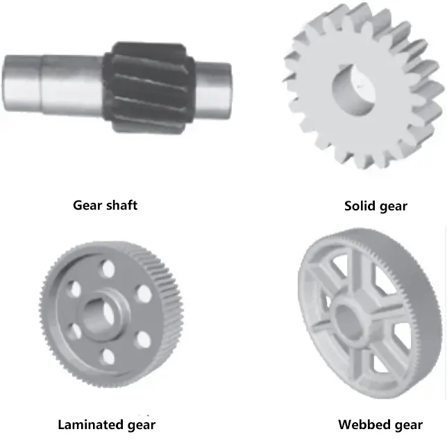
Mainly includes gear shaft, solid gear, web gear, and spoke gear.
(3) Gear failure modes

1) Tooth breakage.
The gear tooth is like a cantilever beam, with the maximum bending stress produced at the tooth root under load. When this stress value exceeds the bending fatigue limit of the material, fatigue cracks occur at the tooth root and continuously expand, causing the tooth to break. Sudden overload, severe wear, and installation or manufacturing errors can also cause tooth breakage.
Solutions: Increase the root fillet radius, eliminate machining tool marks to reduce stress concentration at the tooth root; increase the rigidity of the shaft and support to reduce the degree of local overload; perform surface treatment on the gear teeth to increase the surface hardness.
2) Tooth surface pitting.
The phenomenon of pockmark-like peeling damage caused by fatigue due to the action of approximately pulsating variable stress at a fixed point on the working surface of the gear teeth. Pitting is a common failure mode in closed transmissions. Initially, gears rarely show pitting due to wear. Pitting first appears near the pitch line.
Solutions: Increase tooth surface hardness, reduce surface roughness value of tooth surface, increase lubricating oil viscosity, adopt appropriate profile shift.
3) Tooth surface adhesion.
In high-speed heavy-duty transmissions, high pressure between tooth surfaces and high instantaneous temperatures can break down the lubricating oil film, causing tooth surfaces to stick together. This results in strip-shaped scars on the tooth surface along the sliding direction, known as adhesion.
Solutions: Increase tooth surface hardness, reduce surface roughness value of tooth surface, increase lubricating oil viscosity, limit oil temperature.
4) Tooth surface wear.
Dust, sand particles, metal particles, etc., falling between gear teeth can cause friction and wear between tooth surfaces. In severe cases, it may lead to tooth breakage due to excessive thinning of the tooth surface. Wear is the main failure mode of open transmissions.
Solutions: Use closed transmission, increase tooth surface hardness, reduce surface roughness value of tooth surface, use clean lubricating oil.
5) Plastic deformation.
Under heavy load and high friction, the surface of softer gear teeth will undergo plastic deformation along the direction of friction.
Solutions: Increase tooth surface hardness, increase lubricating oil viscosity.
(4) Gear manufacturing methods
| Method | Form cutting | Generation cutting | |||
| Gear milling | Gear shaping | Gear hobbing | Gear shaving | Gear grinding | |
| Illustration | 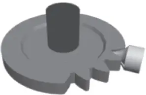 | 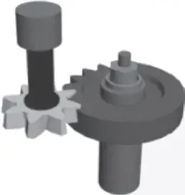 |  | 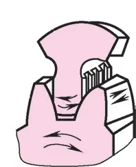 | 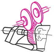 |
| Description | Cutting gears on an ordinary milling machine using a cutter with an axial profile shape identical to the tooth slot shape of the gear being cut | A method of machining using the generating cutting motion between the workpiece and the tool | |||
4. Types of gear transmission
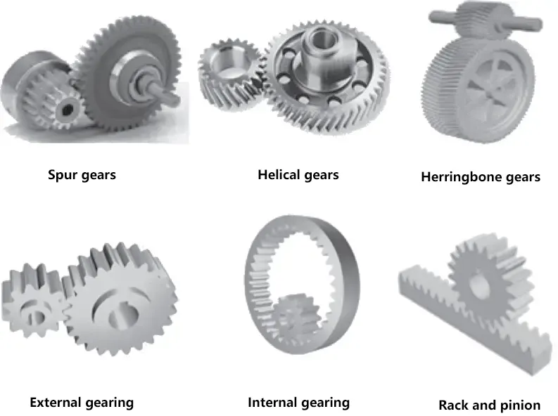
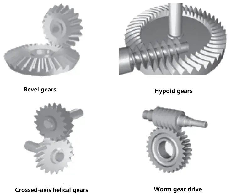
Gear transmission is a type of mechanical transmission that uses gear pairs to transmit motion and power. There are many types of gear transmissions. Based on the relative position of the gear transmission axes, gear transmissions can be divided into two categories: planar gear transmission and spatial gear transmission.
Types of gear transmission
| Planar gear transmission | Classified by gear shape | Spur gear |
| Helical gear | ||
| Herringbone gear | ||
| Classified by meshing form | External meshing | |
| Internal meshing | ||
| Rack and pinion | ||
| Spatial gear transmission | Bevel gear | |
| Hypoid gear | ||
| Crossed helical gear | ||
| Worm gear transmission | ||
5. Gear trains
(1) Classification of gear trains
The simplest form of gear transmission is a mechanism composed of a pair of meshing gears.
However, in machinery, to obtain a very large transmission ratio, or to convert one input shaft speed into multiple output shaft speeds for various reasons, a series of successively meshing gear mechanisms are needed for transmission. A transmission system composed of a series of meshing gears is called a gear train.
According to whether the geometric axis lines of all gears in the gear train are fixed in space during transmission, gear trains can be divided into three main categories: fixed-axis gear trains, planetary gear trains, and compound gear trains.
1) Fixed-axis gear trains.
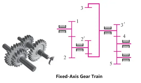
A gear train in which the geometric axis positions of all gears are fixed is called a fixed-axis gear train.
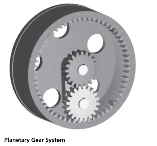
2) Planetary gear trains.
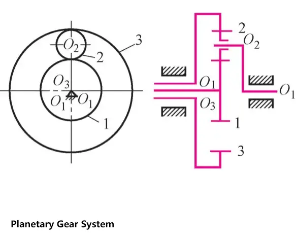
A gear train in which at least one gear’s geometric axis position is not fixed, but rotates around the fixed axis of another gear, is called a planetary gear train.
3) Compound gear trains.
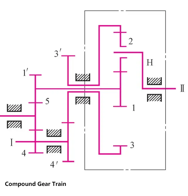
A transmission that includes both fixed-axis gear trains and planetary gear trains, or contains multiple planetary gear systems, is called a compound gear train.
(2) Applications of gear trains
1) Obtaining large transmission ratios. When using a pair of meshing gears for transmission, the transmission ratio is limited by structural constraints. By using gear trains, very large transmission ratios can be achieved to meet low-speed operation requirements.
2) Enabling long-distance transmission. When the center distance between two shafts is large, using a single pair of gears for transmission would result in very large gear sizes, which not only wastes material but also makes the transmission mechanism bulky. By using gear trains, a compact structure can be achieved, enabling longer distance transmission.
3) Multi-speed transmission can be achieved. By using sliding gears and other speed change mechanisms in the gear system to change the transmission ratio, multi-speed transmission can be realized.
4) Can change the direction of rotation. By using bevel gears, idler gears, and other mechanisms in the gear system, the rotation direction of the driven shaft can be changed, thus achieving forward and reverse rotation of the driven shaft.
5) Can achieve motion synthesis or decomposition. Using differential gear trains can combine two independent rotational motions into one rotational motion, or decompose one rotational motion into two independent rotational motions.
VII. Chain Drive
1. Types of Chain Drives
(1) Lifting chains
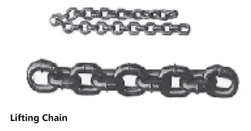
Used for lifting heavy objects in hoisting machinery.
(2) Traction chains
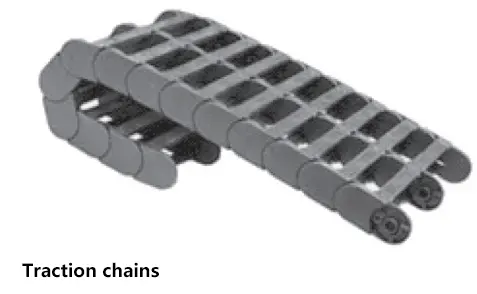
Mainly used for moving heavy objects in chain conveyors.
(3) Transmission chains
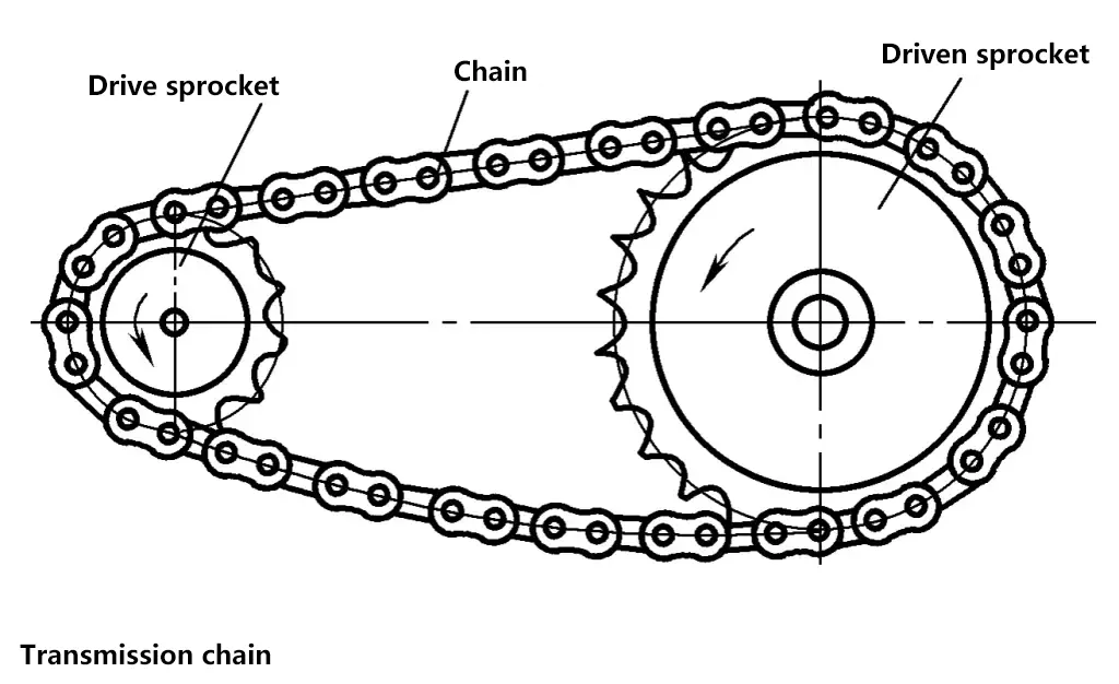
Used for transmitting motion and power in general machinery.
2. Characteristics and Applications of Chain Drives
No sliding, accurate average transmission ratio, low tension force, low load on shafts; high transmission efficiency; more compact than other transmission structures under the same conditions, and can work in harsh environments.
Low manufacturing and installation precision, larger center distance, impact and noise. Not suitable for situations with large load variations and rapid reversals. The main chains used for power transmission are roller chains and silent chains.
3. Sprocket Structure
Depending on the diameter of the sprocket, they are classified as solid, web, welded, and composite types.
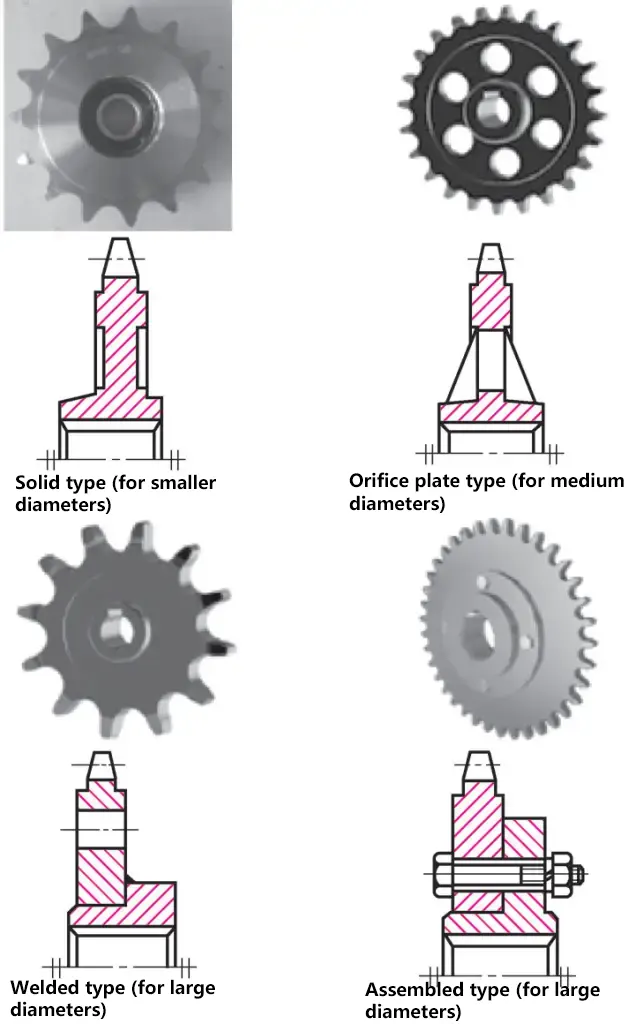
4. Sprocket Materials
Sprocket Materials
| Sprocket Material | Heat Treatment | Tooth Surface Hardness | Application Range |
| 15, 20 | Carburizing, quenching, tempering | 50~60HRC | z≤25, sprockets with impact loads |
| 35 | Normalizing | 160~200HBS | Sprockets with z>25 |
| 45, 50, ZG310-570 | Quenching, tempering | 40~45HRC | Sprockets without severe impact |
| 15Cr, 20Cr | Carburizing, quenching, tempering | 50~60HRC | High-power transmission sprockets with z<25 |
| 40Cr, 35SiMn, 35CrMn | Quenching, tempering | 40~50HRC | Important sprockets using high-quality chains |
| Q215/Q255 | Annealing after welding | 140HBW | Medium-speed, medium-power, larger driven sprockets |
| Gray cast iron with tensile strength not less than HT150 | Quenching, tempering | 260~280HBW | Sprockets with z>50 |
| Fabric-based phenolic laminate | — | — | P<6kW, higher speed, requiring smooth and low-noise transmission |
5. Roller Chains
(1) Structure of Roller Chains
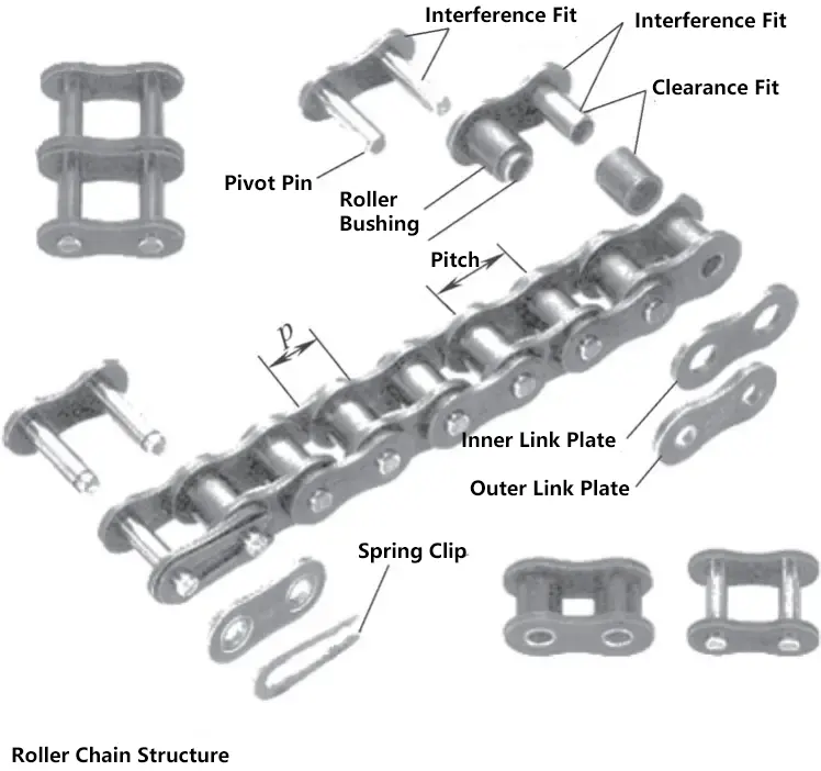
Roller chains consist of inner plates, outer plates, pins, bushings, and rollers. Outer plates are fixed to the pins, inner plates are fixed to the bushings, and rollers can rotate relative to both bushings and pins. Thus, the engagement between the chain and sprocket is mainly rolling friction.
(2) Classification of Roller Chains
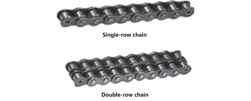
Classified into single-strand and multi-strand chains. Roller chains can be used as single-strand or multiple strands in parallel, with multi-strand parallel use capable of transmitting greater power.
(3) Connecting Methods for Roller Chains
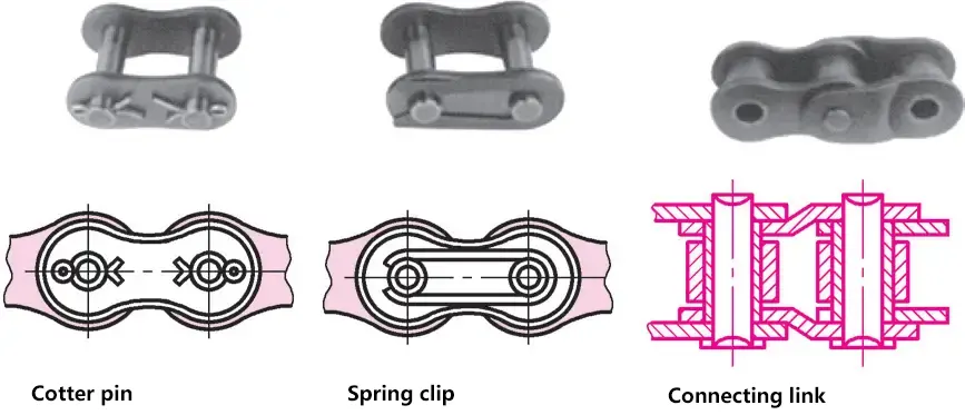
The length of a chain is expressed in the number of links. For an even number of links, inner and outer plates alternate, connected at the joint by a cotter pin or spring clip. For an odd number of links, a transition link is needed for connection. Transition links are complex to manufacture and have poor stress conditions, so they should be avoided in production if possible, and even-numbered links should be used in practical applications.
6. Main Parameters of Roller Chains
(1) Pitch p
The theoretical distance between the centers of two adjacent link pins.
(2) Total number of chain links L p
The total number of links in the entire chain, denoted by Lp . Multi-strand chains are calculated as single-strand chains.
(3) Total chain length l
The total chain length l is the product of the number of links Lp and the pitch p, i.e., l=Lp p.
(4) Strand spacing pt
The distance between the center planes of adjacent strands in double-strand or multi-strand chains.
7. Roller Chain Model Numbers
Roller chains are standardized and divided into A and B series, with A series for design use and B series for maintenance use. The A series is more commonly used. The model number of a roller chain is represented by the chain number + series code A or B.
Chain number – Number of strands – Total number of chain links Standard number
For example: 08B—2—80 GB/T 1243—2006 indicates a roller chain with chain number 08B, 2 strands, and 80 links. The parameters of roller chains can be found in relevant standards.
VIII. Friction Wheel Drive
1. Working Principle of Friction Wheel Drive
Friction wheel drive consists of two friction wheels pressed together, using the friction force generated by direct contact between the two wheels to transmit motion and power. It can be classified into external cylindrical and internal cylindrical types.
2. Transmission Ratio of Friction Wheel Drive
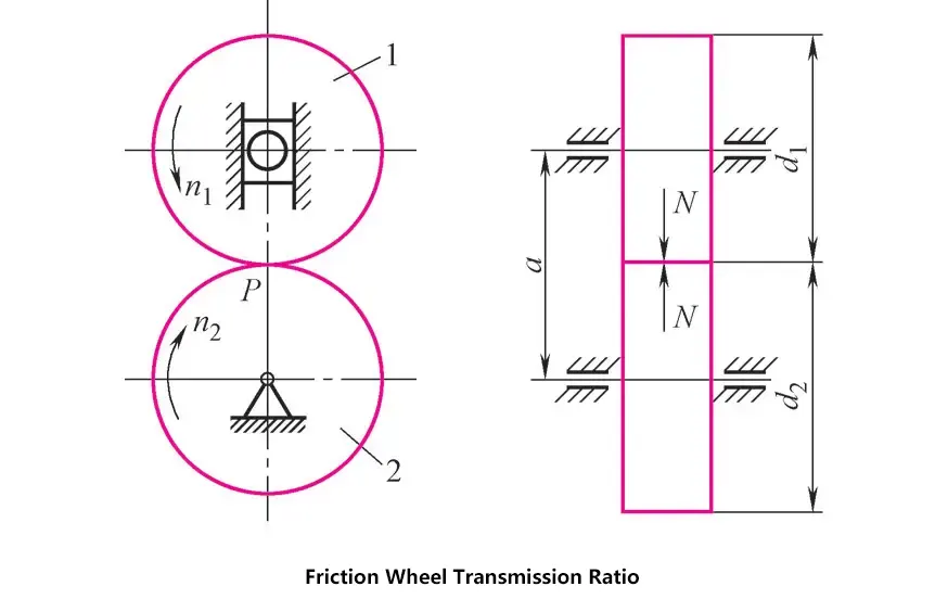
When the driving wheel 1 and driven wheel 2 are pressed together, a pressing force is generated at the contact point P. When the driving wheel 1 rotates counterclockwise, the friction force drives the driven wheel 2 to rotate clockwise. If there is no slippage, the circumferential speeds of the two wheels at point P should be equal, i.e., v 1 =v 2 (m/s).
Because
v 1 =πD1 n1 /1000×60, v2 =πD2 n2 /1000×60
Therefore
i12=n1/n2=D2/D1
Where
- i12 – Transmission ratio of the two friction wheels;
- n1 , n2 – Rotational speeds of the driving and driven wheels (r/min);
- D1 , D2 – Diameters of the driving and driven wheels (mm).
3. Types of Friction Wheel Drives
Based on the relative position of the two wheel axes, friction wheel drives can be classified into two types: parallel axes and intersecting axes.
(1) Parallel Axes
Includes cylindrical friction wheels and grooved friction wheels.
1) Cylindrical friction wheels.
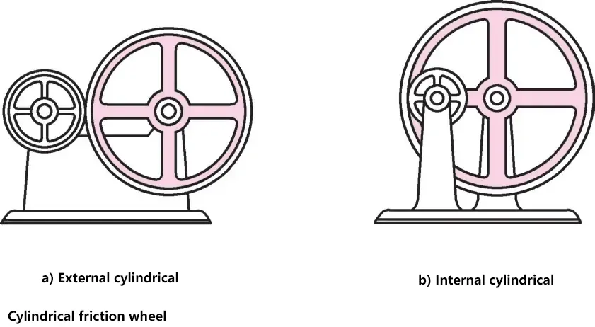
Simple structure, easy to manufacture, high pressing force, divided into external and internal types. Used for low-power transmission, such as instrument adjustment devices.
2) Grooved friction wheels.
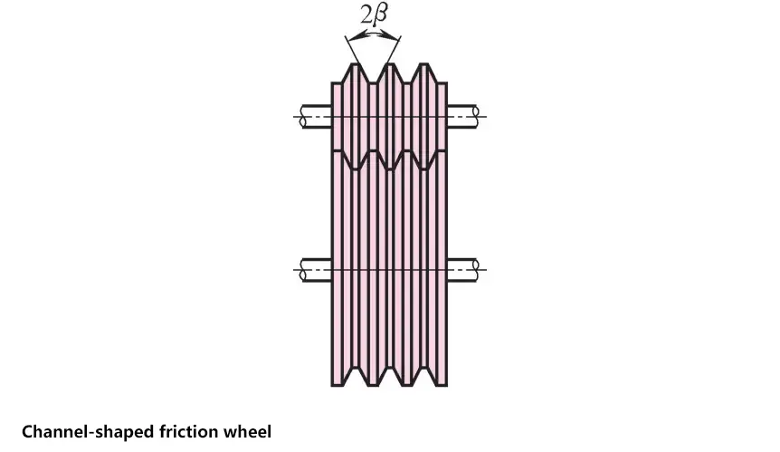
With a groove angle of 2β, they have side contact, which can increase the tangential friction force under the same pressing force, improving transmission power. However, they are prone to heating and wear, have lower transmission efficiency, and require higher manufacturing and installation precision. Suitable for use in mechanisms such as lathe drive systems.
(2) Intersecting Axes
Includes conical friction wheels and face friction wheels.
1) Conical friction wheels.
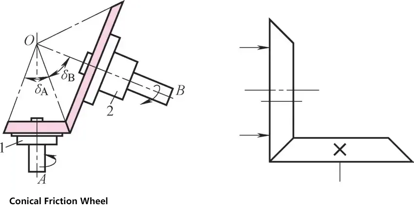
When designing and installing, the relative position of the axes should be correct, and the cone tips should coincide. They can be perpendicular or non-perpendicular. Commonly used in high-power friction presses.
2) Face friction wheels.
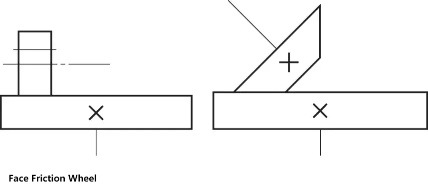
Simple structure, easy to manufacture, high pressing force; prone to heating and wear, low efficiency; high requirements for processing and installation. Divided into cylindrical and conical friction wheels. Used in friction presses and similar applications.
4. Characteristics of Friction Wheel Drives
- Simple structure and easy to manufacture.
- Slips during overload, protecting components.
- Easy to achieve continuous and smooth stepless speed variation, with a wide range of applications.
- Sliding occurs during operation, resulting in low transmission efficiency and inability to maintain accurate transmission ratios.
- Larger structural dimensions, high loads on shafts and bearings, poor ability to withstand overload and impact, thus only suitable for applications with low power transmission.
IX. Belt Drive
Belt drives use friction connections to transmit torque between two shafts.
1. Types of Belt Drives
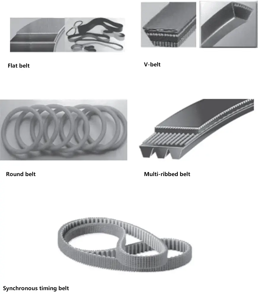
Belt drives consist of belts and pulleys, and can be classified into friction drives and meshing drives.
The main types of belts for friction drives are flat belts, V-belts, round belts, and multi-V belts; the belt for meshing drives is the synchronous timing belt.
2. Flat Belt Drive
(1) Forms of Flat Belt Drives
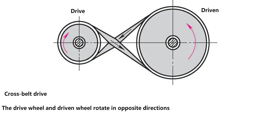
There are open, crossed, semi-crossed, and angle drive types.
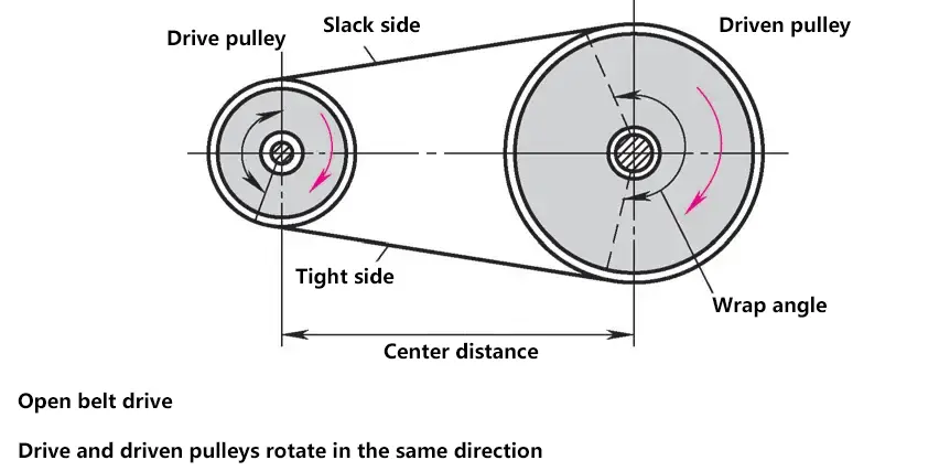
- Open type. The axles of the two wheels are parallel, the symmetrical planes of the two wheel widths coincide, and they rotate in the same direction.
- Crossed type. The axles of the two wheels are parallel, the symmetrical planes of the two wheel widths coincide, and they rotate in opposite directions.
- Semi-crossed type. The axles of the two wheels are skewed in space, with the skew angle generally being 90°.
- Angle drive. The axles of the pulleys intersect.
(2) Types of flat belts
The main types of flat belts include canvas-core flat belts, woven flat belts, nylon-laminated composite flat belts, etc.
1) Canvas-core flat belts.
Made by bonding multiple layers of rubber-coated canvas, available in open-edge and wrapped-edge styles. High tensile strength, good temperature resistance, and low cost; poor heat and oil resistance, open-edge style is more flexible. Used for transmissions with larger center distances.
2) Woven flat belts.
Include cotton-woven, wool-woven, and stitched cotton belts, as well as silk, hemp, and nylon-woven belts for high-speed transmission. Belt surfaces can be rubber-coated or uncoated. Good flexibility, low power transmission, and prone to loosening. Used for medium and small power transmissions.
3) Nylon-laminated composite flat belts.
The load-bearing layer is made of nylon sheets (single or multiple layers), with chrome-tanned leather, rubber-coated canvas, or special fabrics bonded to the working surface. High strength, large friction factor, good flexibility, and resistant to loosening. Used for high-power transmissions; thin versions can be used for high-speed transmissions.
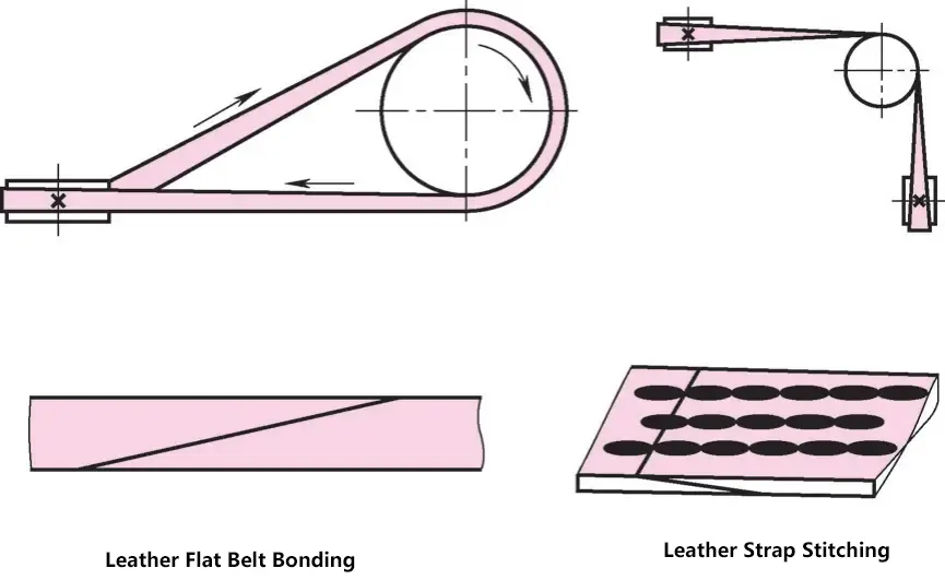
(3) Joining methods for flat belts
Include adhesive bonding for leather flat belts, leather lace stitching, adhesive bonding for canvas flat belts, gut string stitching, and hinge belt fasteners.


(4) Characteristics and applications of flat belt drives
Low impact during transmission, can operate at higher speeds; when transmission speed is high (v≥25m/s), light and thin high-speed flat belts can be used; for lower power transmission, woven flat belts can be used; for higher power transmission, seamless composite belts with nylon sheets or polyester cords as the load-bearing layer and chrome-tanned leather or rubber-coated canvas on the working surface are used.
Hinge buckle belts transmit greater power but have lower transmission speed. At high speeds, they can produce strong vibrations.
(5) Parameters of flat belt transmission
1) Wrap angle α.
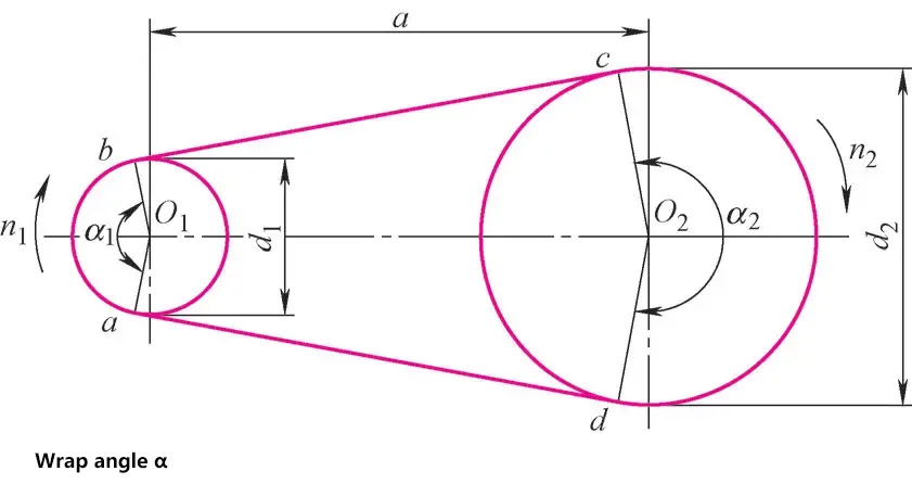
The central angle corresponding to the contact arc between the belt and the pulley. The size of the wrap angle reflects the length of the contact arc between the belt and the pulley rim surface, which is related to the friction between the contact surfaces. If the wrap angle is too small, slipping will occur.
Calculation of wrap angle:
- Open transmission: α 1 =180°-(d2 -d1 )/a×57.3°
- Cross transmission: α 1 =180°-(d2 +d1 )/a×57.3°
- Semi-cross transmission: α 1 =180°+d1/a×57.3°
- For flat belt transmission, the wrap angle α is generally required to be ≥150°
Where
- d 1 , d 2 – diameter of small and large pulleys (mm);
- a – center distance between two pulleys (mm).
2) Belt length L.
The flat belt length is the inner circumference of the flat belt. In practical applications, the calculation of belt length should also consider the tension of the flat belt on the pulley, the sag amount, and the joint length of the flat belt.
Calculation of belt length L:
- Open transmission: L=2a+π/2(d1 +d2 )+(d2 -d1 ) 2 /4a
- Cross transmission: L=2a+π/2(d 1 +d2 )+(d2 +d1 ) 2 /4a
- Semi-cross transmission: L=2a+π/2(d1 +d2 )+(d2 2 +d1 2 )/2a
3) Transmission ratio i.
When calculating the flat belt transmission ratio without considering elastic slip in the transmission. Due to the limitations of the small pulley wrap angle and belt center distance, the transmission ratio of flat belt transmission is generally i≤5.
Calculation of transmission ratio i:
i12=n1/n2=d2/d1
Where
- d1 , d2 – diameter of small and large belt pulleys (mm);
- n1 , n2 – rotational speed of small and large belt pulleys (r/min).
4) Center distance a.
The distance between the axles of two pulleys when the belt is tensioned is called the center distance.
Calculation of center distance a:
Actual center distance for open transmission:
a=A+√(A2-B)
Where
A=L/4-π(d1 +d2 )/8, B=(d2 -d1 ) 2 /8
3. V-belt transmission
(1) Structure and standards of V-belts
1) Structure of V-belts.
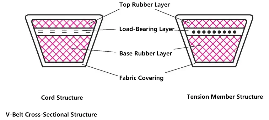
The cross-sectional structure of commonly used V-belts is divided into two categories: canvas structure and cord structure, composed of four parts: top rubber, load-bearing layer, bottom rubber, and cover fabric layer. The cover fabric material is canvas, which is the protective layer of the V-belt; the top and bottom rubber materials are rubber, the top rubber can be stretched, and the bottom rubber can be compressed; the load-bearing layer mainly bears the tensile force.
2) Standards for V-belts.
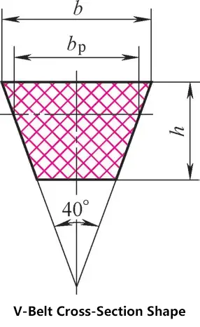
V-belts have been standardized. Commonly used V-belts mainly include regular V-belts, narrow V-belts, wide V-belts, and half-width V-belts, all with a wedge angle α of 40°. Regular V-belts are the most widely used.
GB/T11544—2012 specifies seven types of regular V-belts: Y, Z, A, B, C, D, and E. The cord structure only has four types: Z, A, B, and C.
Cross-sectional dimensions of regular V-belts
| Type | Pitch width b p /mm | Top width b/mm | Height h/mm | Wedge angle α/(°) |
| Y | 5.3 | 6 | 4 | 40 |
| Z | 8.5 | 10 | 6 | 40 |
| A | 11.0 | 13 | 8 | 40 |
| B | 14.0 | 17 | 11 | 40 |
| C | 19.0 | 22 | 14 | 40 |
| D | 27.0 | 32 | 19 | 40 |
| E | 32.0 | 38 | 23 | 40 |
3) Reference length Ld of V-belts.
A V-belt is a seamless loop belt. The fiber layer that maintains constant length and width under specified tension is called the neutral layer. The length measured along the neutral layer is called the pitch length L d , also known as the reference length or nominal length.
The marking of a V-belt consists of three parts: type, reference length, and standard number.
V-belt marking B1560GB/T11544—2012 indicates a B-type V-belt with a reference length of 1560mm.
V-belt types and length series (unit: mm)
| Y | Z | A | B | C | D | E |
| 200 | 405 | 630 | 930 | 1565 | 2740 | 4660 |
| 224 | 475 | 700 | 1000 | 1760 | 3100 | 5040 |
| 250 | 530 | 790 | 1100 | 1950 | 3330 | 5420 |
| 280 | 625 | 890 | 1210 | 2195 | 3730 | 6100 |
| 315 | 700 | 990 | 1370 | 2420 | 4080 | 6850 |
| 355 | 780 | 1100 | 1560 | 2715 | 4620 | 7650 |
| 400 | 920 | 1250 | 1760 | 2880 | 5400 | 9150 |
| 450 | 1080 | 1430 | 1950 | 3080 | 6100 | 12230 |
| 500 | 1330 | 1550 | 2180 | 3520 | 6840 | 13750 |
| 1420 | 1640 | 2300 | 4060 | 7620 | 15280 | |
| 1540 | 1750 | 2500 | 4600 | 9140 | 16800 | |
| 1940 | 2700 | 5380 | 10700 | |||
| 2050 | 2870 | 6100 | 12200 | |||
| 2200 | 3200 | 6815 | 13700 | |||
| 2300 | 3600 | 7600 | 15200 | |||
| 2480 | 4060 | 9100 | ||||
| 2700 | 4430 | 10700 | ||||
| 4820 | ||||||
| 5370 | ||||||
| 6070 |
(2) Structure and materials of V-belt pulleys
1) Structure of V-belt pulleys.
The structure of V-belt pulleys usually consists of a rim, hub, and spokes. The rim is used for installing the transmission belt, and there are grooves on the rim corresponding to the belt type and number.
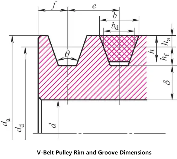
V-belt pulleys must be easy to manufacture, lightweight and evenly distributed, easy to align during installation, and have minimal stress induced during casting or welding.
Dimensions of V-belt pulley rim and grooves (unit: mm)
| Item | Symbol | Y | Z | A | B | C | D | |
| Reference width | bd | 5.3 | 8.5 | 11 | 14.0 | 19 | 27.0 | |
| Groove depth above reference line | hamin | 1.6 | 2.0 | 2.75 | 3.5 | 4.8 | 8.1 | |
| Groove depth below reference line | hfmin | 4.7 | 7.0 | 8.7 | 10.8 | 14.3 | 19.9 | |
| Groove spacing | ext: e | 8±0.3 | 12±0.3 | 15±0.3 | 19±0.4 | 25.5±0.5 | 37±0.6 | |
| Groove edge distance | fmin | 6 | 7 | 9 | 11.5 | 16 | 23 | |
| Minimum rim thickness | δmin | 5 | 7.0 | 6 | 10.8 | 10 | 12 | |
| Fillet radius | r1 | 0.2~0.5 | ||||||
| Pulley width | B | B=(z-1)e+2f z—number of grooves | ||||||
| Outer diameter | da | da=dd+2ha | ||||||
| Groove angle θ | 32° | Corresponding reference diameter dd | ≤60 | — | — | — | — | — |
| 34° | — | ≤80 | ≤118 | ≤190 | ≤315 | — | ||
| 36 | >60 | — | — | — | — | ≤475 | ||
| 38° | — | >80 | >118 | >190 | >315 | >475 | ||
| Limit deviation | ±30′ | |||||||
Structure of V-belt pulley
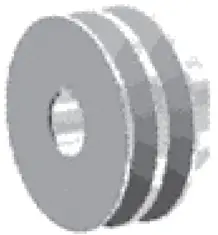
2) Material of V-belt pulley.
The material of V-belt pulley is selected based on the diameter or speed of the V-belt pulley.
Material of V-belt pulley
| V-belt pulley material | HT150, HT200 | HT200, steel pulley | Steel plate welded type | Plastic pulley | Aluminum alloy pulley |
| Usage range | v≤30m/s | v>30m/s | d≥500mm | Low-speed transmission, low-power transmission, v<15m/s | High-speed transmission |
(3) Characteristics and applications of V-belt transmission
Advantages: Smooth transmission, low noise, can buffer and absorb vibration; simple structure, low installation precision, easy maintenance; in case of overload, the belt will slip on the pulley, providing safety protection. Disadvantages: The belt has elasticity, elastic sliding exists, transmission ratio is inaccurate; large overall dimensions, low transmission efficiency.
Application scenarios: Situations requiring smooth transmission, where precise transmission ratio is not required, or for medium to small power and larger center distances.
X. Hydraulic and Pneumatic Transmission
1. Hydraulic transmission
Hydraulic transmission is a type of transmission that uses liquid as the working medium, utilizing the pressure energy of the liquid to transmit power and perform control.
(1) Characteristics and applications of hydraulic transmission
Advantages: Compared to mechanical and electrical transmissions, hydraulic transmission devices have compact structure, high transmission force, precise positioning, smooth movement, easy automation, good component lubrication, and long service life.
Disadvantages: Relatively low transmission efficiency, not suitable for long-distance transmission, not suitable for working in high or low temperature conditions, high precision requirements for hydraulic components, high cost, etc.
Applications: Mechanical industry, metallurgical industry, petroleum industry, engineering construction, shipbuilding, military, aviation, aerospace, and other industrial sectors.
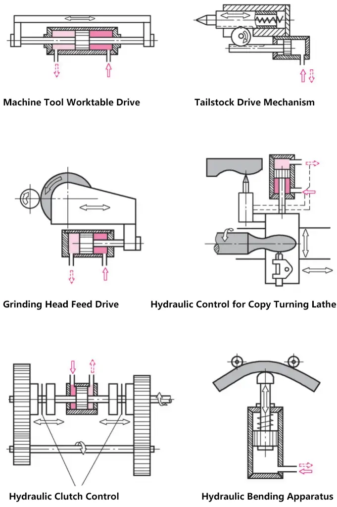
(2) Working principle of hydraulic transmission and composition of hydraulic transmission system
1) Working principle of hydraulic transmission
The hydraulic system uses a hydraulic pump to convert the mechanical energy of the prime mover into pressure energy of the fluid. Through changes in fluid pressure energy, it transmits energy. After transmission through various control valves and pipelines, it uses hydraulic cylinders or hydraulic motors and other hydraulic actuators to convert fluid pressure energy into mechanical energy, thereby driving the working mechanism to achieve linear reciprocating motion and rotational motion.
The fluid used is called the working medium, generally mineral oil, which functions similarly to transmission elements like belts, chains, and gears in mechanical transmission. Hydraulic pumps are used to deliver fluid and generate pressure, hydraulic cylinders are used to obtain linear motion, and hydraulic motors are used to obtain rotational motion. Below is a schematic diagram of a hydraulic jack.
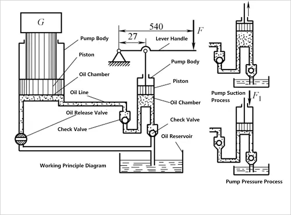
2) Composition of hydraulic transmission system
Any simple and complete hydraulic transmission system consists of the following four parts:
- Power element (hydraulic pump). Its function is to supply pressurized oil to the hydraulic system, serving as the system’s power source.
- Actuating element (hydraulic cylinder or motor). Its function is to perform external work under the action of pressurized oil.
- Control elements. Such as relief valves, throttle valves, directional valves, etc., their function is to control the system’s pressure, flow, and direction respectively, to meet the requirements of the actuating elements for force, speed, and direction of motion.
- Auxiliary elements. Such as oil tanks, pipes, pipe fittings, filters, accumulators, etc.
2. Pneumatic transmission
Pneumatic transmission is a form of transmission that uses compressed air as the working medium, utilizing air pressure for energy transfer. It is widely used in production and daily life, such as bicycle and car tire inflation, and car painting.
(1) Basic composition of pneumatic transmission system
A pneumatic transmission system consists of four parts: air source device, actuating components, control components, and auxiliary components.
Composition of pneumatic transmission system
| Name | Function | Example |
| Air source device | Converts mechanical energy provided by the prime mover (electric motor, engine) into pressure energy of gas, providing energy for various pneumatic equipment | Air compressor |
| Actuating components | Convert gas pressure energy into mechanical energy and deliver it to working parts | Various pneumatic cylinders |
| Control components | Control the pressure, flow, and flow direction of compressed air, as well as the action sequence of actuating components, to make the actuating components complete the predetermined motion pattern | Various valves, such as pressure valves, flow valves, directional valves |
| Auxiliary components | Purify, lubricate, silence compressed air and connect components, playing a very important role in maintaining reliable, stable, and long-lasting operation of the pneumatic system | Various filters, dryers, lubricators, silencers, and piping components |
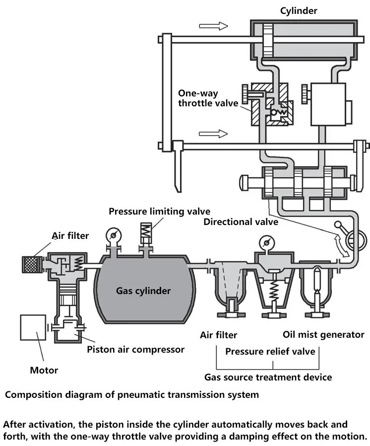
After the pneumatic transmission system is turned on, the piston in the cylinder automatically moves back and forth, with the one-way throttle valve providing damping effect on the motion.
(2) Characteristics of pneumatic transmission
Compared to mechanical, electrical, and hydraulic transmission, pneumatic transmission has the following characteristics.
Advantages:
- The working medium is air, which saves energy and can be discharged into the atmosphere after use without polluting the environment.
- The properties of air are less affected by temperature, can work at high temperatures, and will not burn or explode.
- Air has good fluidity, convenient for centralized supply and long-distance transmission.
- Pneumatic transmission has quick action, fast response, high reliability of pneumatic components, and long service life.
- Pneumatic transmission devices have simple structure, low cost, and are easy to standardize, serialize, and universalize.
Disadvantages:
- Air has high compressibility, resulting in poor stability of system action.
- Working pressure is relatively low (generally 0.3~1MPa), making it difficult to obtain larger output force or torque.
- Noise is relatively high, requiring silencers for exhaust.
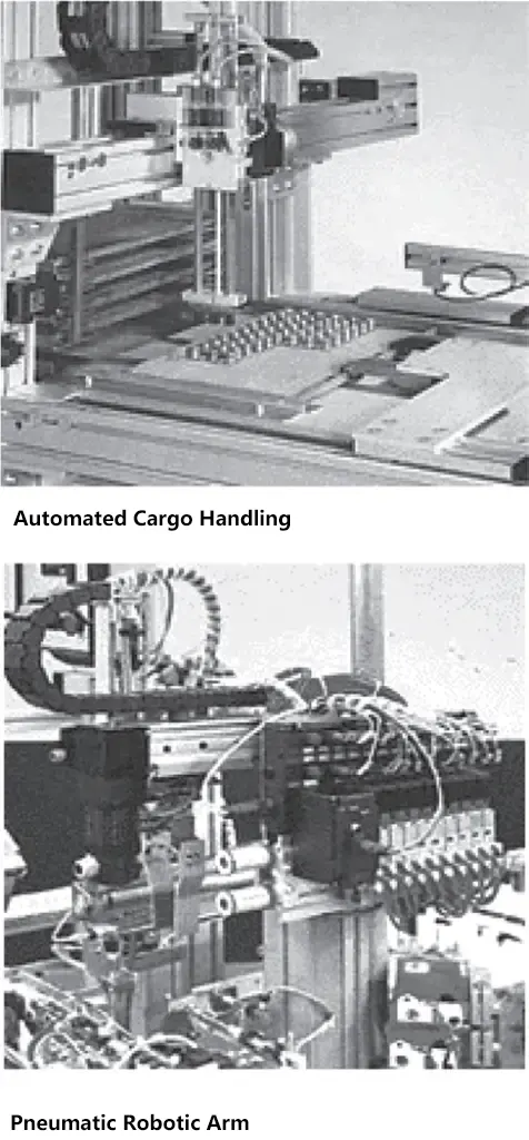
(3) Applications of pneumatic transmission technology
1) Material handling equipment.
Such as clamping, conveying, positioning, orienting, and material flow distribution.
2) General applications.
Such as packaging, filling, measuring, locking, shaft driving, material conveying, part orientation, part sorting, component stacking, component stamping or molding marking, and door control.
3) Material processing.
Such as drilling, turning, milling, sawing, grinding, and finishing.
The following figure shows an example of a pneumatic transmission system used for automatic cargo loading and unloading and pneumatic manipulators.
