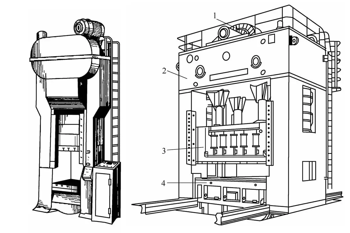
(1) The main components of the mechanical press
The commonly used mechanical press is mainly the crank press, which is widely used in material forming (plastic forming) as equipment that obtains the necessary force and linear displacement for material forming through the crank connecting rod mechanism. It can perform processes such as stamping, extrusion, forging, etc., and is widely used in the automotive industry, agricultural machinery, aviation industry, electronic instrument industry, hardware light industry, and other fields.
According to the function of each part of the press, it can be divided into the following components:
1) Working mechanism.
The working execution mechanism of the equipment consists of a crank, connecting rod, and slider, converting rotary motion into reciprocating linear motion. Since the working mechanism is a rigid crank connecting rod mechanism, the press has fixed upper and lower limit positions (top and bottom dead centers) during operation, which can precisely control the dimensions of the formed parts.
2) Transmission system.
The transmission system consists of belt drive and gear drive, transmitting the energy of the electric motor to the working mechanism. During the transmission process, the speed gradually decreases, and the torque gradually increases.
3) Operating mechanism.
The operating mechanism mainly consists of a clutch, a brake, and the corresponding electrical system. After the motor starts, it controls the operating state of the working mechanism, allowing it to work intermittently or continuously.
4) Energy section.
The energy section consists of an electric motor and a flywheel. The energy for the machine operation is provided by the electric motor. After starting, the motor accelerates the flywheel, and the flywheel provides the short-term working energy for the press, playing a role in storing and releasing energy.
5) Support section.
The support section consists of the machine body, worktable, and fasteners, etc. It connects all parts of the press into a whole.
6) Auxiliary systems.
The auxiliary systems include the pneumatic system, lubrication system, overload protection device, air cushion, quick die change, blanking device, monitoring device, etc. They enhance the safety and ease of operation of the press. For new presses, the cost proportion of this system shows an increasing trend.
(2) Classification of crank presses
Currently, crank presses are mainly classified based on the structure of the bed, divided into open and closed crank presses. Closed crank presses can be further divided into single-point closed presses (see Figure 3-57), double-point closed presses, and four-point closed presses (see Figure 3-58), etc.
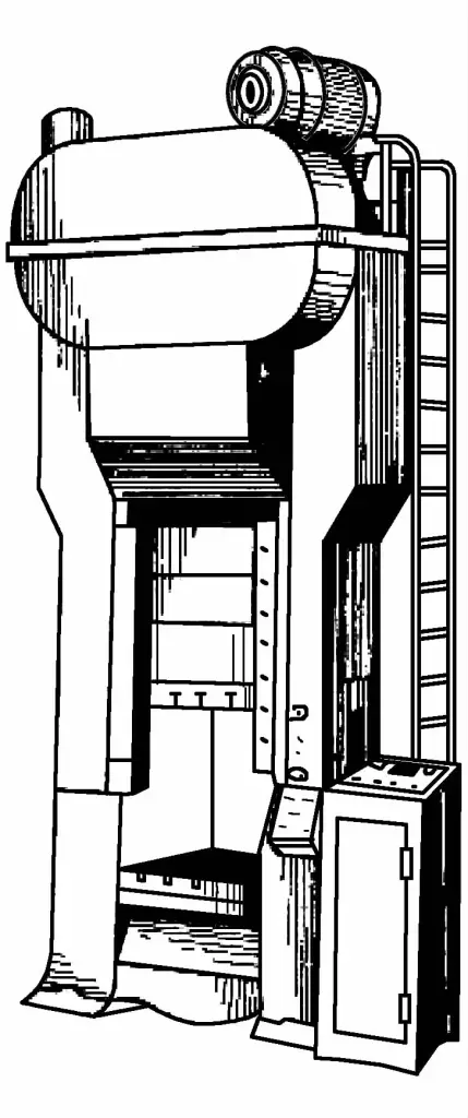
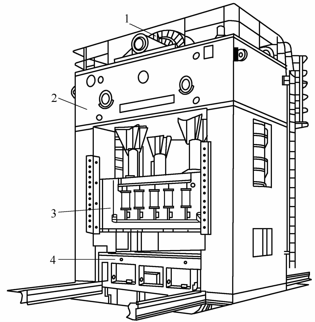
1—Transmission System
2—Machine Body
3—Slider
4—Workbench
The bed of the open crank press is “C” shaped, with the front and both left and right sides of the body open, facilitating mold installation, adjustment, and forming operations. However, the rigidity of the body (especially the angular rigidity) is poor.
Deformation under load affects the precision of the parts and reduces the life of the mold, suitable for small presses, commonly used under 1000kN.
The body of the closed crank press is a frame structure, with the front and back open and the sides closed. Mold installation and forming operations are carried out on the front and back sides.
The vertical deformation caused by the deformation of the body under load can be eliminated by adjusting the mold closing height. It does not affect the precision of the parts and the running accuracy of the mold, suitable for medium and large crank presses.
In addition to the above classification methods, there are some other classification methods:
According to the technological use, it can be classified into general crank presses, deep drawing presses, high-speed punching presses, hot die forging presses, cold extrusion presses, etc. These presses have improved the crank slider mechanism to make its force capacity and motion curve more suitable for the corresponding forming process requirements.
According to the number of sliders, it can be classified into single-action crank presses and double-action crank presses. Single-action refers to having one slider in the working mechanism, and double-action refers to having two sliders, inner and outer sliders, with the inner slider installed inside the outer slider, each mechanism driven separately.
Double-action crank presses are also known as deep drawing presses (see Figure 3-59). For complex-shaped large thin sheet metal parts, especially cover parts, it is advisable to use a dedicated deep drawing press.
Therefore, the deep drawing press is an important equipment in the processing of agricultural cover parts. Generally, a deep drawing press has two sliders, the outer slider is used for edging, and the inner slider is used for deep drawing.
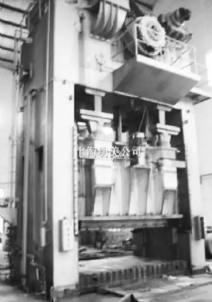
The outer slider of the double-action deep drawing press is fitted with an inner slider to achieve double action.
The movement of the inner slider and the outer slider of the double-action deep drawing press must maintain a certain relationship to meet the requirements of the deep drawing process, and the movement relationship of the inner and outer sliders is represented by a working cycle diagram.
Figure 3-60 is the slider working cycle diagram of the JB46-315 double-action deep drawing press.
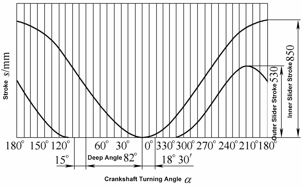
The movement pattern of the inner slider is similar to that of the general crank press slider. The outer slider is driven by multiple mechanisms and makes an approximate intermittent movement. During operation, the outer slider presses the blank 10°~15° ahead of the inner slider, the inner slider starts deep drawing at about α≤82°, and deep drawing ends at α=0°.
On the return stroke, the outer slider lags behind the inner slider by 10°~15°, the purpose of which is to prevent the workpiece from getting stuck on the punch, thus the clamping angle of the outer slider is set to 100°~110°.
When the inner slider returns to the top dead center, the outer slider has already passed the top dead center and moved downward a certain distance, this distance is called the lead-in travel, approximately equal to 0.1~0.15 of the slider travel, “lead-in” ensures that the slider presses the blank ahead in the next working stroke, and the “lead-in” amount should not be too large to ensure that the workpiece can be removed from the die.
The double-action deep drawing press is also equipped with an air cushion, which can eject the workpiece after the deep drawing is finished. Since the outer slider lags behind the inner slider by 10°~15° during the return stroke, to avoid damaging the workpiece within this 10°~15° range, the air cushion should be equipped with a return lag device to synchronize its rise with the outer slider.
The double-action deep drawing press has the following process characteristics:
1) Stable and reliable edging force.
For complex deep-drawn parts, different deep drawing ribs are usually set on the mold to adjust and control the resistance of metal flow. The double-action deep drawing press, due to its outer slider having sufficient pressure to completely deform the metal at the deep drawing ribs, fully utilizes the process role of the deep drawing ribs.
2) Operates smoothly without impact.
The outer slider of the double-action deep drawing press is already at the bottom dead center when starting to edge, so the impact force is very small when it contacts the workpiece.
If elastic elements or air cushions are used, the slider has a certain speed when the edging ring contacts the workpiece, causing larger impacts at the start of edging, leading to vibrations in the edging ring and a sudden increase in edging force, squeezing out the lubricant between the edging ring and the blank, increasing the friction during deep drawing, and raising the possibility of rupture in deep-drawn parts.
3) Easy to mechanize operations.
When using a double-action deep drawing press, the deep drawing die is mounted correctly, i.e., the deep drawing female die is below, the male die is above, the part is drawn downwards, and the periphery of the blank can be kept constant in height, facilitating the use of robotic arms for automated operations.
4) Appropriate deep drawing speed.
As it is a specialized press, the speed of the inner slider for deep drawing better meets the requirements of the deep drawing process.

