Material Strength Testing: Mechanical Properties Guide
Have you ever wondered how engineers ensure that the materials used in buildings, bridges, and vehicles can withstand the stresses…
How do metals resist forces without breaking? This article explores the fascinating world of metal properties, covering key aspects like strength, plasticity, hardness, and toughness. Discover how metals withstand tension, endure stress, and maintain their integrity in various applications. By understanding these properties, you’ll gain insights into material selection and performance, crucial for engineering and manufacturing success.

The properties of metallic materials include service performance and process performance. Service performance refers to the properties exhibited during use (such as mechanical properties, physical properties, chemical properties, etc.). Process performance refers to the properties exhibited by metallic materials during various processing processes (such as casting performance, forging performance, welding performance, heat treatment performance, cutting performance, etc.).
Generally, the selection of metallic materials is mainly based on mechanical properties. The mechanical properties of metallic materials refer to the properties related to or including the stress-strain relationship shown by metallic materials under the action of force, that is, the resistance exhibited by metallic materials under the action of force. Common mechanical properties include strength, plasticity, hardness, toughness, fatigue strength, etc.
The ability of metallic materials to resist deformation and fracture under the action of force is called strength, which is usually measured by the tensile test method.
Before the test, the metallic material to be tested is made into a tensile specimen of a certain shape and size according to the standard GB/T 228.1—2010. During the test, the standard specimen is clamped on the tensile testing machine and slowly loaded (static load).
The elongation of the specimen increases with the increase of force until the specimen is broken. The automatic recording device of the testing machine can draw a force-elongation curve showing the relationship between the force and the corresponding elongation during the entire tensile test process. Figure 1 shows the force-elongation curve of annealed low carbon steel.
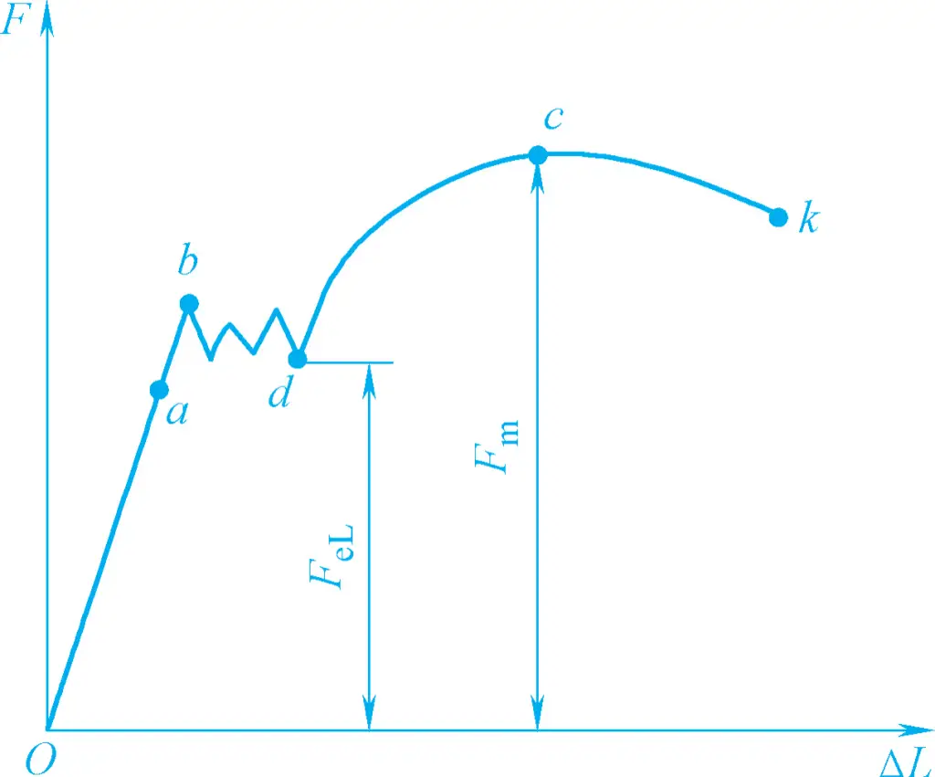
As can be seen from Figure 1, when the force F is zero, the elongation ΔL is zero. When the force gradually increases from zero to point a, the elongation of the specimen increases proportionally with the force. At this time, if the force is removed, the specimen can completely return to its original shape and size, indicating that the specimen is in the elastic deformation stage.
When the force exceeds point a, the specimen not only undergoes elastic deformation but also plastic deformation (or permanent deformation), meaning that after the force is removed, the specimen cannot completely return to its original shape and size. When the force is increased to point b, a horizontal (or sawtooth-shaped) segment appears on the curve, indicating that the force does not increase, but the specimen continues to elongate. This phenomenon is called “yielding.”
When the force exceeds point d (corresponding force FeL ), the elongation of the specimen increases with the increase of force, indicating that the specimen has undergone a large amount of plastic deformation. When the force continues to increase to point c (corresponding force Fm ), the specimen shows a phenomenon of local diameter reduction, commonly known as “necking.” When the force gradually decreases to point K, the specimen breaks at the necking point.
The minimum stress at which a metallic material exhibits yielding is called yield strength, denoted by the symbol R eL (MPa), which is
ReL=FeL/S0
Where
Some metallic materials (such as high carbon steel, cast iron, etc.) do not exhibit obvious yielding during the tensile test, making it difficult to measure yield strength.
In such cases, the specified residual elongation strength R is used in engineering to reflect the material’s resistance to yielding, which is the stress corresponding to the specified percentage of gauge length after the tensile force is removed. For example, the stress at a specified residual elongation of 0.2% is denoted by Rr0.2 .
Rr0.2=Fr0.2/S0
In the formula, F r0.2 refers to the force (N) the specimen withstands when the residual elongation is 0.2% after the tensile force is removed.
Yield strength indicates the ability of metallic materials to resist slight plastic deformation. When the stress on the material is below the yield strength, only slight plastic deformation occurs; when it exceeds the yield strength, significant plastic deformation occurs.
The maximum tensile stress that a specimen can withstand before breaking is called tensile strength, denoted by the symbol Rm (MPa).
Rm=Fm/S0
In the formula, Fm is the maximum force (N) the specimen withstands before breaking.
Tensile strength indicates the ability of metallic materials to resist the maximum uniform plastic deformation or fracture. Some materials with poor plasticity do not exhibit obvious yielding during the tensile test, but tensile strength is relatively easy to measure. Therefore, tensile strength is also an important indicator for measuring material strength.
The ability of metallic materials to undergo the maximum plastic deformation before breaking under the action of force is called plasticity. The greater the plastic deformation before breaking, the better the plasticity. Common plasticity indicators include elongation after fracture and reduction of area, which are also measured by tensile tests on specimens.
The percentage of the residual elongation of the gauge length after the specimen breaks to the original gauge length is called elongation after fracture, denoted by the symbol A.
A=(Lu-Lo)/Lo×100%
Where
The percentage of the maximum reduction in the cross-sectional area of the specimen after fracture to the original cross-sectional area of the specimen is called the reduction of area, denoted by the symbol Z.
Z=(So-Su)/So×100%
Where
Both elongation after fracture and reduction of area are important performance indicators of materials. The larger their values, the better the plasticity of the material.
Hardness refers to the ability of a metal material to resist deformation, especially permanent deformation such as indentation or scratching, i.e., the ability to resist local plastic deformation and damage. Generally, the higher the hardness, the better the wear resistance and the higher the strength.
In current production, the most commonly used method for measuring hardness is the indentation hardness test. It uses an indenter of a certain geometric shape, which is pressed into the surface of the metal material being tested under a certain load. The hardness value is determined based on the degree of deformation after indentation.
Using the same indenter and under the same load, if the degree of deformation after indentation is greater, the hardness of the material is lower; conversely, the hardness is higher. The Brinell hardness and Rockwell hardness tests are the most widely used in production.
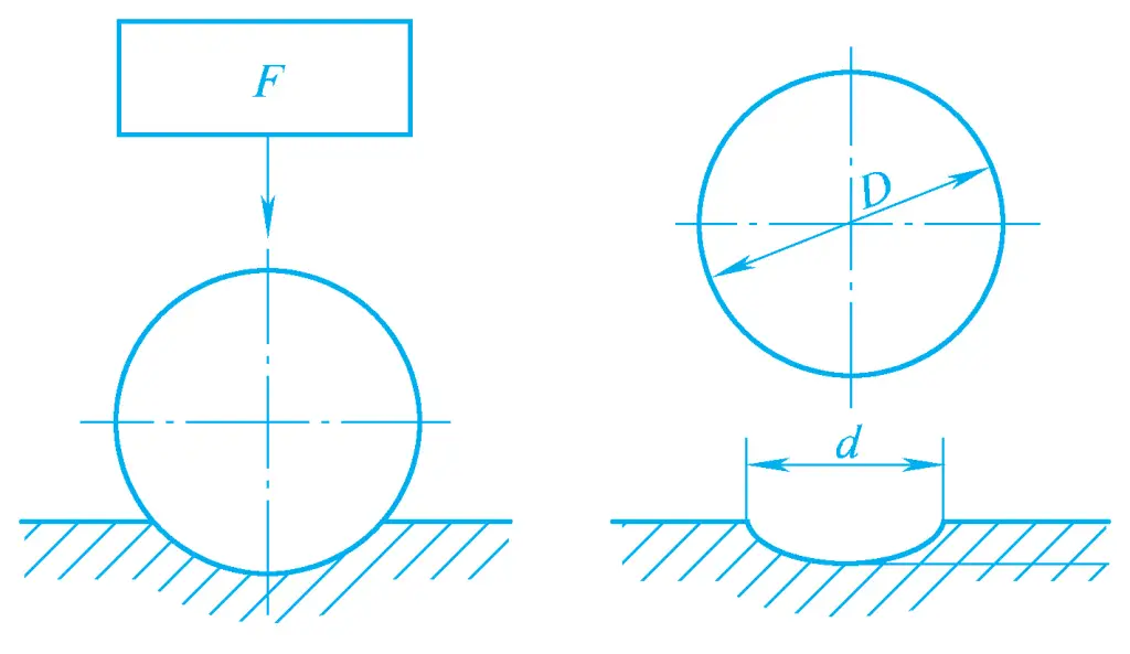
The principle of Brinell hardness measurement is to use a hard alloy ball with a certain diameter D as the indenter, which is pressed into the surface of the metal being tested under a specified test force F (see Figure 2). After maintaining the force for a specified time, the test force is removed, and the diameter d of the indentation on the surface of the tested metal is measured. The Brinell hardness value is calculated by multiplying the ratio of the test force to the spherical surface area of the indentation by a constant (0.102), denoted by the symbol HBW. The upper limit of the Brinell hardness test range is 650HBW.
The Brinell hardness value is expressed by the hardness number, hardness symbol, and test conditions (ball diameter, test force, and holding time). For example, 350HBW5/750 indicates a Brinell hardness value of 350 measured using a 5mm diameter hard alloy ball under a test force of 7.35kN for 10~15s. The larger the hardness value, the higher the hardness of the tested material.
The principle of Rockwell hardness measurement is to use a diamond cone indenter with an apex angle of 120° or a hardened steel ball indenter with a diameter of 1.5875mm. The indenter is pressed into the surface of the metal being tested under the initial test force and the combined initial and main test forces (see Figure 3). After maintaining the force for a specified time, the main test force is removed, and the hardness of the metal material is determined based on the increment of the residual indentation depth.
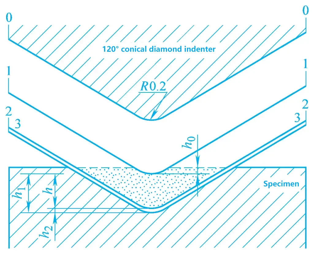
In Figure 3, position 0-0 is the initial position of the cone indenter, i.e., the position when the indenter is not in contact with the surface of the tested metal; position 1-1 is the depth ho of the indenter under the initial test force of 98.07N (10kgf); position 2-2 is the depth h1 of the indenter after applying the main test force; after removing the main test force, the elastic deformation of the tested metal recovers, causing the indenter to rise to position 3-3 by h2 .
Therefore, the hardness of the tested metal can be measured by the depth h (residual indentation depth) of the plastic deformation caused by the main test force. The larger the indentation depth h, the lower the hardness of the tested metal; conversely, the higher the hardness.
To align with the concept that the larger the value, the higher the hardness, a constant N minus h/0.002 is commonly used as the Rockwell hardness value, denoted by the symbol HR. The Rockwell hardness value can be directly read from the dial of the hardness tester.
HR=N1-h/0.002
In the formula, N is a constant. When using a diamond indenter, N=100; when using a hardened steel ball indenter, N=130.
The Rockwell hardness is expressed by writing the hardness value before the symbol, such as 60HRC. The common test conditions and application ranges of Rockwell hardness are shown in Table 1.
Table 1 Common test conditions and application ranges of Rockwell hardness (excerpted from GB/T 230.1—2009)
| Hardness Symbol | Indenter Type | Applicable Range | Initial Test Force/N | Main Test Force/N | Total Test Force/N | Application Example |
| HRA | Diamond Cone | 20~88HRA | 98.07 | 490.3 | 588.4 | Carbide, surface hardened layer, carburized layer, etc. |
| HRB | Diameter 1.5875mm ball | 20~100HRB | 98.07 | 882.6 | 980.7 | Non-ferrous metals, annealed steel, normalized steel, etc. |
| HRC | Diamond cone | 20~70HRC | 98.07 | 1373 | 1471 | Quenched and tempered steel, quenched steel, etc. |
Strength, plasticity, and hardness are mechanical performance indicators measured under static load. In fact, many machine parts and tools often work under impact load. At this time, in addition to meeting the strength, plasticity, and hardness under static load, they must also have sufficient ability to resist impact load.
The ability of metal to resist impact load without being damaged is called impact toughness, and the impact toughness of metal materials can be determined by impact tests.
The pendulum impact test is currently the most widely used method in engineering technology. The metal material to be tested is made into a standard impact specimen and tested on a special pendulum testing machine.
During the test, the specimen is placed on the support of the testing machine, and the pendulum with a mass of m is raised to a height h1 , so that it obtains a certain amount of energy, and then the pendulum is allowed to fall freely to break the specimen. After breaking the specimen, the pendulum continues to rise forward to a height h2 . The potential energy difference of the pendulum during this process is the energy consumed to break the specimen, which is the impact absorption energy, denoted by K, with the unit J (Joule).
The greater the impact absorption energy, the better the impact toughness of the material; conversely, the worse the impact toughness, that is, the greater the brittleness.
Many mechanical parts such as engine crankshafts, connecting rods, gears, springs, etc., are often subjected to loads that periodically change in magnitude and direction. This type of load is called alternating load.
Under the action of alternating load, although the maximum stress value borne by the part is much lower than its yield strength, after many cycles, the part will fracture without significant external deformation. This type of fracture is called fatigue fracture. Fracture often occurs suddenly, so it is very dangerous and can often cause serious accidents.
The maximum stress value that a metal material can withstand without causing fracture under countless alternating loads is called the fatigue strength of the material.
It is not possible to perform countless stress cycles in actual tests, so it is stipulated that for steel, when the number of stress cycles reaches 107 times, the maximum stress at which the part does not fracture is considered its fatigue strength; for non-ferrous metals and some ultra-high strength steels, when the number of stress cycles is 108 times, the maximum stress at which the part does not fracture is considered its fatigue strength.