The metal cutting process refers to the process in which the tool cuts off the excess metal layer from the workpiece through cutting motion, forming chips and a machined surface. A series of phenomena occur during this process, such as chip formation, generation of cutting force, cutting heat and cutting temperature, and tool wear.
I. Deformation Coefficient, Chips, and Built-up Edge
1. Deformation Coefficient and Types of Chips
(1) Deformation Coefficient
The metal in the cutting layer forms chips after cutting, with the length shortened and thickness increased compared to the metal in the cutting layer, indicating that the metal in the cutting layer has deformed, as shown in Figure 1.
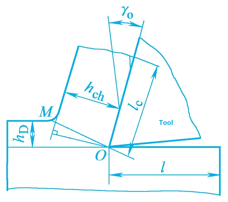
The degree of deformation can be approximately measured by the deformation coefficient ξ. The deformation coefficient is equal to the ratio of the chip thickness to the thickness of the metal in the cutting layer, and also equal to the ratio of the length of the metal in the cutting layer to the length of the chips.
ξ=l/lc=hch/hD>1
It can be seen that the larger the deformation coefficient value, the more severe the cutting deformation.
(2) Types of Chips
According to the different shapes of chips, they are usually divided into the following four types:
1) Ribbon Chips
The shape is ribbon-like, with a smooth bottom surface and no obvious cracks on the back, showing a slight serrated shape. This type of chip is often formed when machining plastic metals such as non-alloy steel, alloy steel, copper, aluminum, and other materials.
2) Segmented Chips
The bottom surface of the chip is relatively smooth, and the back surface is locally cracked into nodules. This type of chip is easily obtained when cutting brass or cutting steel at low speeds.
3) Granular chips
The chip fractures into uniform granules along the thickness direction. This type of chip can be obtained when cutting lead or cutting steel at very low speeds.
4) Fragmented chips
When cutting brittle metals such as cast iron and bronze, the cutting layer undergoes almost no plastic deformation and fractures brittlely, resulting in irregular fine-grained chips. Table 1 shows the factors affecting chip morphology and their impact on cutting force.
Table 1 Factors affecting chip morphology and their impact on cutting force
| Classification of chip morphology | Granular chips | Nodular chips | Ribbon chips | |
| Schematic diagram of chip morphology | 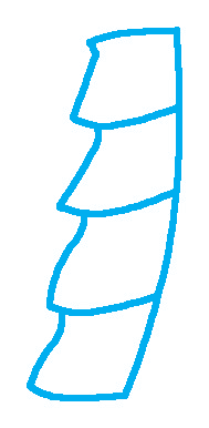 | 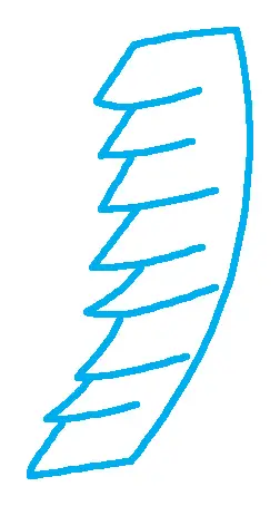 | 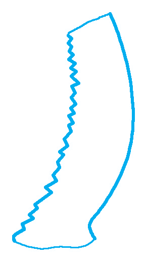 | |
| Factors affecting chip morphology and their mutual transformation | 1. Tool rake angle 2. Feed rate (cutting thickness) 3. Cutting speed | Small ↔ Large Large (thick) ↔ Small (thin) Low ↔ High | ||
| Impact of chip morphology on cutting process | 1. Fluctuation of cutting force 2. Stability of the cutting process 3. Surface roughness value of the machined surface 4. Chip breaking effect | Large ↔ Small Poor ↔ Good Large ↔ Small Good ↔ Poor | ||
2. Built-up edge
(1) Concept of built-up edge
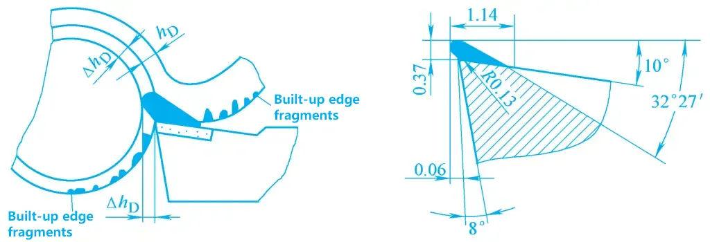
Within a certain range of cutting speeds, when machining steel, non-ferrous metals, and other plastic materials, a piece of high-hardness metal appears on the rake face near the cutting edge. It surrounds the cutting edge and covers part of the rake face, acting as a substitute for the cutting edge to perform cutting operations on the workpiece. This piece of metal, with a hardness about 2 to 3 times that of the workpiece material, is called a built-up edge, as shown in Figure 2.
(2) Formation and Growth of Built-up Edge
There are many explanations for the formation of built-up edge, which is generally believed to be caused by the adhesion of chips on the rake face. Under certain machining conditions, as the temperature and pressure between the chips and the rake face increase, the friction also increases, causing the flow rate of the deformation layer in the chips near the rake face to slow down, resulting in a “stagnation” phenomenon. The closer the metal layer is to the rake face, the lower the flow rate.
When the temperature and pressure increase to a certain extent, the bottom metal in the stagnation layer adheres to the rake face. When the shear stress in the bottom metal of the chips exceeds the shear yield strength limit of the metal, the flow rate of the bottom metal becomes zero and it is sheared off, adhering to the rake face.
This adhesive layer undergoes severe plastic deformation, increasing its hardness. During continued cutting, the hard adhesive layer shears off the soft metal layer, accumulating layer by layer, and gradually increasing in height, forming a built-up edge. Thus, adhesion and work hardening are necessary conditions for the growth of built-up edge.
(3) Detachment and Disappearance of Built-up Edge
The grown built-up edge may undergo local fracture or detachment due to external forces or vibrations. When the temperature and pressure are suitable, the built-up edge starts to form and grow again. The formation, growth, and detachment of built-up edge is a periodic dynamic process.
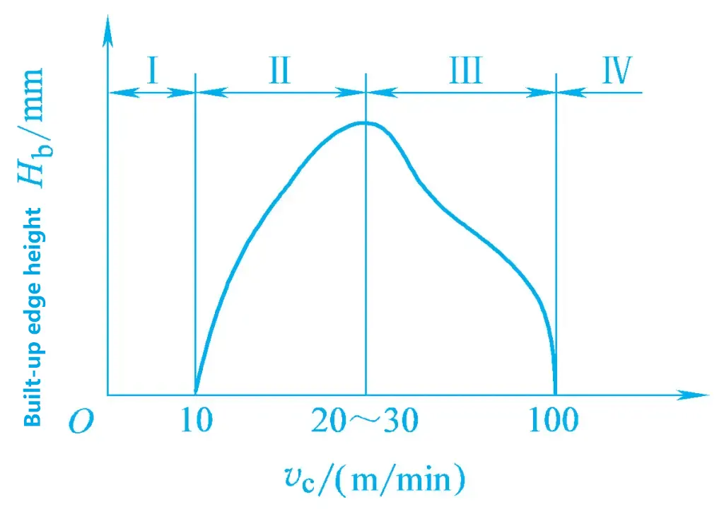
Experiments show that the decisive factor for the formation of built-up edge is the cutting temperature. At very low and very high cutting temperatures, built-up edge is not easily formed. In the medium temperature range, for example, when cutting medium carbon steel at a cutting temperature of 300-380°C, severe adhesion occurs, and the built-up edge reaches a significant height. Additionally, factors such as the pressure between the tool and the chips, the roughness of the rake face, and the adhesion strength also affect the size of the built-up edge.
(4) Advantages and Disadvantages of Built-up Edge
The advantage of built-up edge in cutting is that it covers part of the rake face and cutting edge, replacing the cutting edge in work, thus protecting the cutting edge and increasing the actual working rake angle of the tool.
The disadvantage is that the built-up edge increases the lateral dimensions of the tool, causing overcutting. When the built-up edge detaches, it may carry away metal particles from the rake face, accelerating the wear of the rake face. The formation process of built-up edge causes fluctuations in cutting force, affecting the machining accuracy and surface roughness of the workpiece. Therefore, built-up edge is beneficial for rough machining but detrimental for finish machining.
(5) Measures to Reduce or Avoid Built-up Edge
- Avoid cutting at speeds that produce built-up edge (see Figure 3), i.e., use low-speed or high-speed cutting. However, low-speed machining has low efficiency, so high-speed cutting is often used.
- Use tools with a large rake angle to reduce the contact pressure between the tool and the chips.
- Reduce the plasticity of the workpiece material, increase the hardness of the workpiece, and reduce the tendency for work hardening.
- Other measures include reducing the feed rate, reducing the surface roughness of the rake face, and using cutting fluids appropriately.
II. Cutting Force
The interaction force between the tool and the workpiece during cutting is called the cutting force, and the work done by the cutting force is the cutting work.
1. Source of Cutting Force
The source of cutting force comes from two aspects: the deformation resistance generated by the deformation of the metal in the cutting layer and the friction resistance generated by the friction between the chips, workpiece, and tool.
2. Decomposition of Cutting Force
The magnitude and direction of the cutting force are not easily measured directly. To meet the needs of design and process analysis, the cutting force is generally decomposed, and it is meaningful to study its components in certain directions.
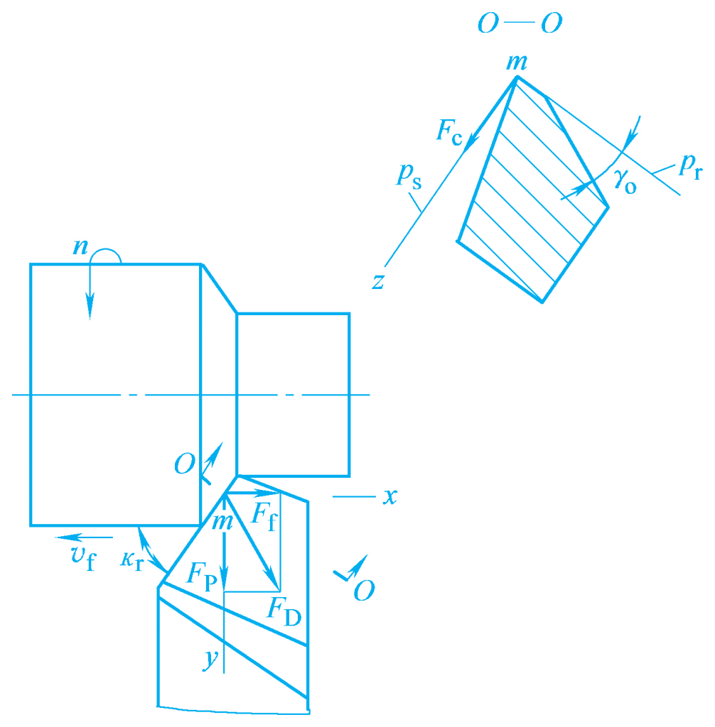
As shown in Figures 4 and 5, the cutting force F can be decomposed into three mutually perpendicular components F c , F p , and F f .
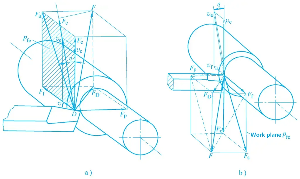
a) Decomposition of forces exerted by the tool on the workpiece
b) Decomposition of forces exerted by the workpiece on the tool
(1) Main Cutting Force Fc
The component of the cutting force in the main motion direction.
(2) Back force Fp
The component of the cutting force in the direction perpendicular to the assumed working plane. The assumed working plane is defined by a point selected on the cutting edge, perpendicular to the base plane, and parallel to the assumed feed motion direction.
(3) Feed force Ff
The component of the cutting force in the feed motion direction.
The cutting force F can be decomposed into Fc and FD , and FD can be decomposed into Fp and Ff . Their relationship is:
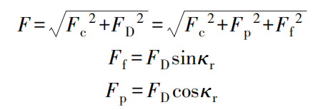
The actual significance of each component force during turning is as follows: The main cutting force is the largest component, consuming about 95% of the total cutting power. It acts in the main motion direction and is the primary basis for calculating the strength of the machine tool’s main motion mechanism, the strength of the tool holder and insert, designing machine tool fixtures, and selecting cutting parameters.
The back force does not consume power during external turning. It acts in the direction where the rigidity of the workpiece and the machine tool is the weakest, easily causing deformation of the workpiece in the horizontal plane, affecting machining accuracy, and easily causing vibration. It is the main basis for verifying the rigidity of the machine tool.
The feed force acts on the feed motion mechanism of the machine tool, consuming about 5% of the total power. It is the main basis for verifying the strength of the machine tool’s feed mechanism.
3. Calculation of cutting force
In actual production, an exponential formula is often used to calculate the cutting force. Specific calculation formulas can be found in relevant reference materials.
4. Factors affecting cutting force
The higher the strength and hardness of the workpiece material, the greater the cutting force. When the depth of cut is doubled, the cutting force increases by about one fold; when the feed rate is doubled, the cutting force increases by 70% to 80%. Increasing the rake angle reduces the cutting force; the main cutting edge angle Kr affects all three component forces Fc , Fp , and Ff , but has a greater impact on Fp and Ff .
According to the previous formula, increasing the main cutting edge angle reduces the back force and increases the feed force. The impact of Kr on Fc can be divided into two situations: when Kr varies within the range of 30° to 60°, as Kr increases, Fc decreases; when Kr varies within the range of 75° to 90°, as Kr increases, Fc increases.
5. Cutting power
Cutting power refers to the power consumed in the cutting zone during cutting. It is the sum of the power consumed by the main cutting force Fc and the feed force Ff . Since the power consumed by the feed force Ff is very small, it is usually neglected. Therefore, when Fc and vc are known, the cutting power Pc is
Pc = (Fc vc × 10-3 ) / 60
Where
- Pc – Cutting power, unit: kW;
- Fc – Main cutting force, unit: N;
- vc – Cutting speed, unit: m/min.
The required power of the machine tool motor PE should be
PE = Pc / η
In the above formula, η is the transmission efficiency of the machine tool, generally taken as η=0.75 to 0.85. This formula is the main basis for verifying and selecting the machine tool motor.
III. Cutting heat and cutting temperature
Another important physical phenomenon that occurs during cutting is cutting heat and cutting temperature. The cutting heat causes the cutting temperature to rise, resulting in thermal deformation of the workpiece and the machine tool, affecting the machining accuracy and surface quality of the workpiece. Cutting temperature is the main factor affecting tool life. Therefore, studying cutting heat and cutting temperature has important practical significance.
1. Cutting heat
The work done by the elastic and plastic deformation of the metal in the cutting layer under the action of the tool, and the friction between the chip and the rake face, and between the machined surface of the workpiece and the flank face, all convert into cutting heat. The cutting heat is conducted away by the chip, workpiece, tool, and surrounding medium.
During turning, about 50% to 86% of the cutting heat is carried away by the chip, 10% to 40% is conducted into the workpiece, 3% to 9% is conducted into the tool, and 1% is conducted into the surrounding medium; during drilling, about 28% of the cutting heat is carried away by the chip, 15% is conducted into the drill bit, 52% is conducted into the workpiece, and 5% is conducted into the surrounding medium.
Increasing the cutting speed can increase the proportion of heat carried away by the chip, reduce the heat conducted into the workpiece, and even less heat is conducted into the tool. Therefore, although the cutting temperature in the cutting zone is very high during high-speed cutting, the tool can still work normally.
2. Cutting temperature
Cutting temperature generally refers to the average temperature in the contact area between the chip and the rake face of the tool. The level of cutting temperature depends on the amount of heat generated at that location and the rate of heat dissipation. Through calculation and measurement, it is known that the average temperature is highest in the chip. The highest temperature on the rake face is not at the cutting edge or the cutting edge, but at a small distance from the cutting edge.
3. Factors affecting cutting temperature
The cutting speed has the greatest impact on the cutting temperature; as the cutting speed increases, the cutting temperature rises accordingly. The feed rate has a smaller impact, and the depth of cut has an even smaller impact. Increasing the rake angle reduces the cutting temperature, but the rake angle should not be too large; if it is too large, the cutting temperature will instead increase. Increasing the main deflection angle raises the cutting temperature.
IV. Tool Wear and Tool Life
During the cutting process, the tool operates under high temperature and high pressure. Therefore, the tool not only cuts the chips but also gets worn out. When the tool wear reaches a certain level, the surface roughness of the workpiece increases, the shape and color of the chips change, and a heavy sound is emitted during the cutting process, accompanied by vibrations. At this point, the tool must be re-sharpened or replaced with a new one.
1. Tool Wear
(1) Forms of Tool Wear
Tool wear refers to the phenomenon where the material of the tool is worn away by the chips or the workpiece on the contact surface between the tool and the workpiece or chips. This type of wear is called normal wear. If the tool edge breaks or fractures due to impact, vibration, thermal effects, etc., it is called abnormal wear. The normal wear forms of the tool include the following:
1) Flank Wear
When cutting plastic materials, if the cutting thickness is large, a crescent-shaped wear pattern appears behind the cutting edge on the rake face of the tool (see Figure 6a). The crescent area is the place with the highest cutting temperature. As the wear intensifies, the crescent area gradually deepens and widens, and when it approaches the cutting edge, the edge may suddenly break off. The amount of wear on the rake face is indicated by the width KB and depth KT of the crescent area.
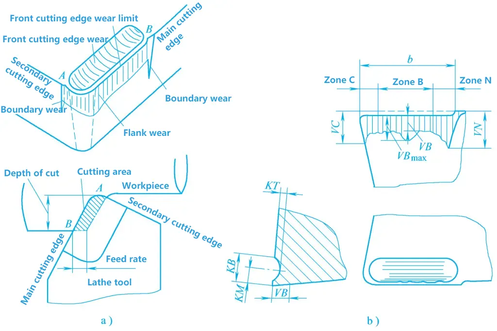
a) Flank and Rake Face Wear
b) Representation of Wear Amount
2) Flank Wear
This refers to wear that mainly occurs on the flank face. After flank wear, a small facet with a zero-degree clearance angle is formed. When cutting plastic metals with a small cutting thickness or brittle metals, due to less friction and lower temperature on the rake face, wear mainly occurs on the flank face. The amount of flank wear is uneven.
As shown in Figure 6b, at the tool tip (C area), the heat dissipation conditions and strength are poor, resulting in greater wear, which is indicated by VC. Near the cutting edge close to the workpiece surface (N area), due to the hard skin of the blank or work hardening, the wear is also greater, indicated by VN. Only in the middle of the cutting edge (B area) is the wear relatively uniform, indicated by VB, with the maximum wear amount indicated by VBmax .
3) Simultaneous Flank and Rake Face Wear
When cutting plastic metals with a moderate cutting thickness, simultaneous wear of the rake face and flank face often occurs.
Tool wear mainly occurs due to mechanical friction and thermochemical effects under high temperature and high pressure. Generally, the higher the cutting temperature, the faster the tool wear.
(2) Tool Wear Process
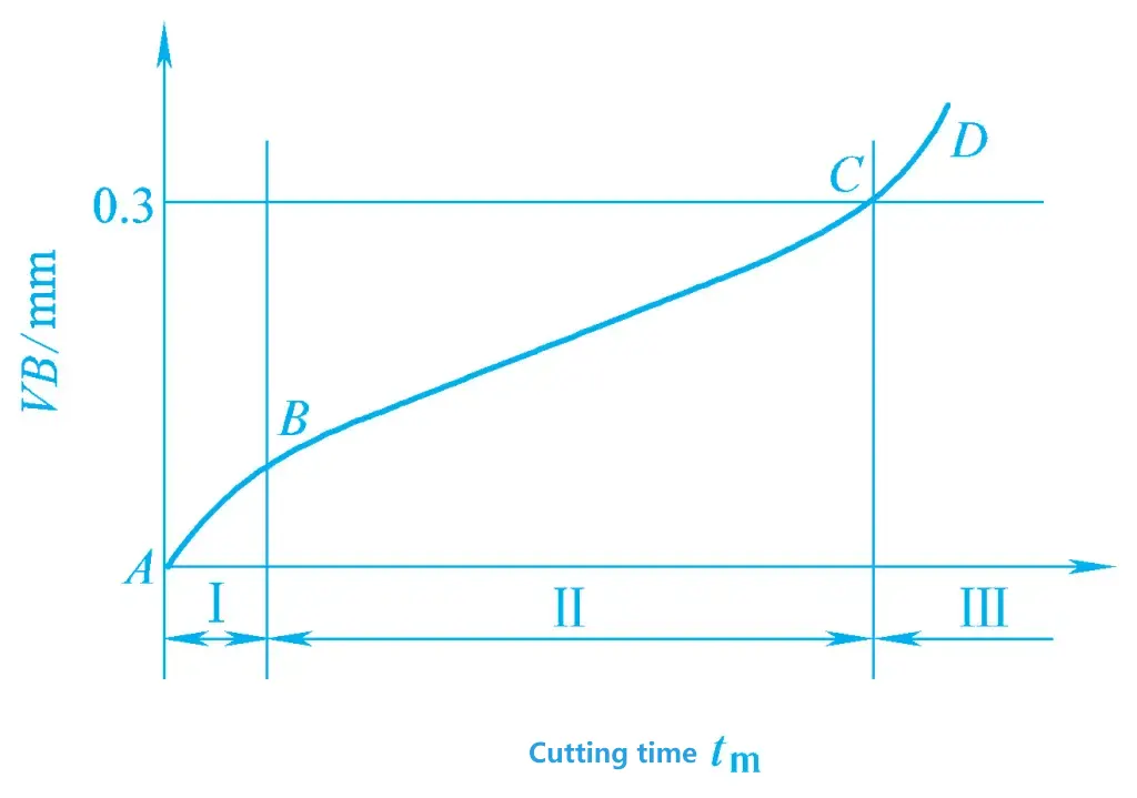
Under normal wear conditions, the amount of tool wear gradually increases with the cutting time. Taking flank wear as an example, its typical wear process is roughly divided into three stages as shown in Figure 7.
1) Initial Wear Stage
(Stage AB in the figure) The wear is relatively fast in the short time after the tool starts cutting. This is because the surface roughness of the tool face is high after grinding, and the surface layer structure is not wear-resistant.
2) Normal Wear Stage
(Stage BC in the figure) As the cutting time increases, the wear amount increases at a relatively uniform speed. This is because the uneven and non-wear-resistant surface layer of the tool has been worn away, forming a stable region. Therefore, the wear speed is slower than before, but the wear amount gradually increases with the cutting time. This stage is also the effective working stage of the tool.
3) Rapid Wear Stage
(Stage CD in the figure) When the tool wear amount reaches a certain value, the wear accelerates rapidly, and the tool subsequently fails. This is due to prolonged cutting time, deteriorating contact conditions between the tool and the workpiece, excessive friction, a sharp increase in cutting temperature, and reduced tool strength and hardness. In production, to use the tool reasonably and ensure processing quality, the cutting edge should be re-sharpened or the tool replaced before this stage arrives.
(3) Tool Blunting Standard (Wear Limit)
The tool blunting standard refers to the specified wear value at which the tool should be re-sharpened or the cutting edge replaced (indexable insert). Otherwise, it will affect processing quality, increase the wear of the tool and grinding wheel during re-sharpening, reduce tool utilization, and increase grinding time.
The national standard GB/T 16461—2016 specifies the blunting standards for high-speed steel tools, carbide tools, and ceramic tools as follows:
- When the flank wear band in the B area is in the form of normal wear, the average width of the flank wear band VB=0.3mm.
- When the wear band on the flank face B area is not in the form of normal wear, such as scratches, chipping, etc., the maximum width of the wear band on the flank face VB max = 0.6mm.
- The depth of the crater KT = 0.06 + 0.3f.
In addition, during finishing, the criterion for tool dullness is often whether the amount of tool wear affects surface roughness and dimensional accuracy.
2. Tool Life
(1) The concept of tool life
Tool life T is defined as the total cutting time from the start of cutting with a newly sharpened tool until it reaches the tool wear limit, denoted as T, with the unit in minutes.
(2) Factors affecting tool life
1) The impact of cutting speed on tool life
Increasing the cutting speed vc will raise the cutting temperature, accelerate tool wear, and thus reduce tool life T. Among the three elements of cutting parameters, v c has the greatest impact on T.
2) The impact of feed rate and depth of cut
Increasing f and ap both reduce tool life T, but increasing f raises the cutting temperature more significantly, thus having a greater impact on T; whereas increasing αp raises the cutting temperature less, thus having a smaller impact on T.
3) Tool geometry parameters
Reasonable selection of tool geometry parameters can extend tool life. In production, tool life is often used as a measure of whether the tool geometry parameters are reasonable.
Increasing the rake angle γo reduces the cutting temperature and improves tool life, but if the rake angle is too large, the tool strength decreases and heat dissipation worsens, which can reduce tool life. Therefore, there is an optimal value for the rake angle, which can be determined through cutting experiments.
Reducing the main cutting edge angle Kr , the secondary cutting edge angle kr , and increasing the tool nose radius rε can improve the tool’s heat transfer capability and reduce the cutting temperature, both of which can extend tool life.
4) Workpiece material
The higher the strength, hardness, and toughness of the workpiece material, and the lower the elongation, the higher the cutting temperature during cutting, and the shorter the tool life.
5) Tool material
Tool material is an important factor affecting tool life. Reasonable selection of tool materials, the use of coated tool materials, and the use of new tool materials are effective ways to extend tool life.

