I. Manual Metal Arc Welding
Manual metal arc welding is an arc welding method where the electrode is manually operated for welding. It is the earliest developed and still the most widely used welding method among various arc welding methods.
Manual metal arc welding is achieved by heating and melting the metal with the arc heat generated between the electrode coated with external flux and the workpiece. Figure 1 shows the welding process of manual metal arc welding. Before welding, the electrode holder 3 and the workpiece 1 are connected to the two poles of the welding machine 4 output terminal, and the electrode 2 is clamped with the electrode holder 3.
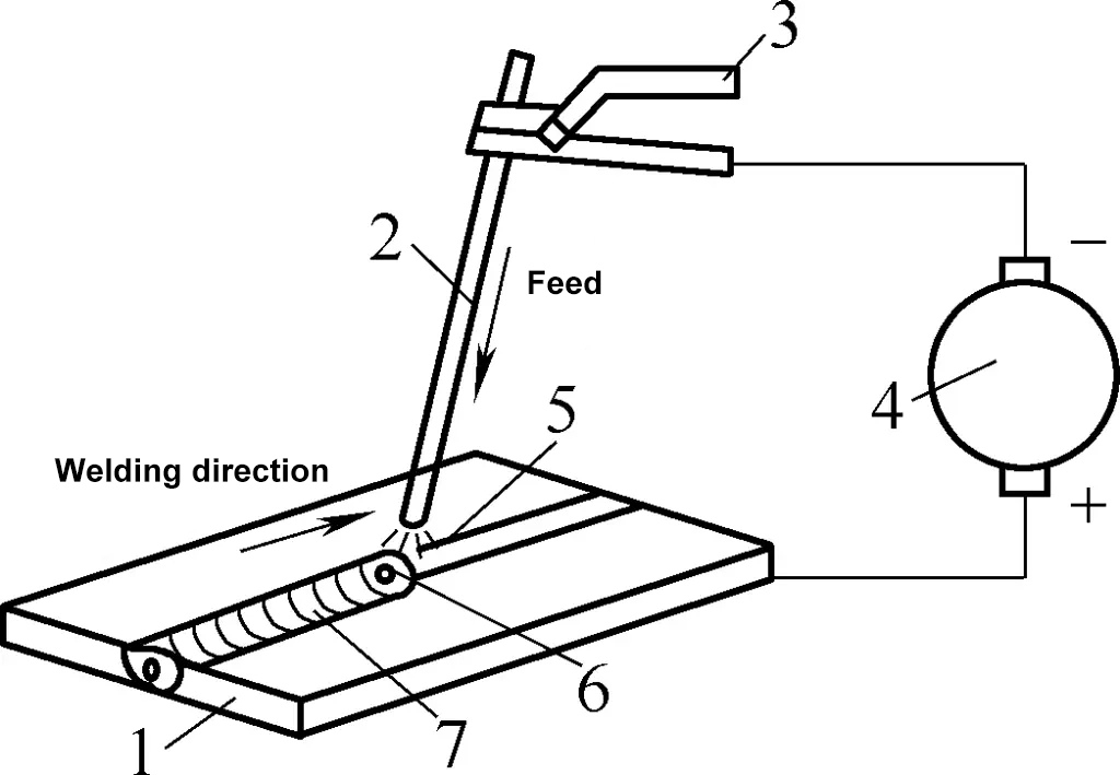
1—Workpiece
2—Electrode
3—Electrode Holder
4—Welding Machine
5—Welding Arc
6—Molten Pool
7—Weld Seam
During welding, the welding arc 5 is ignited between the electrode and the workpiece. The high temperature (6000 to 7000°C) generated by the arc melts the base material of the electrode and the workpiece at the welded part (with a melting point generally around 1500°C) to form a molten pool 6. As the electrode moves along the welding direction, new molten pools continuously form, while the liquid metal of the previous molten pool cools and solidifies, forming a weld seam 7, thus joining the workpieces together.
Manual metal arc welding has characteristics such as high arc temperature, concentrated heat, simple equipment, convenient and flexible operation, and adaptability to welding under various conditions. It is a commonly used method in welding production and is widely applied to welding different thicknesses and positions of carbon steel, alloy steel, stainless steel, heat-resistant steel, high-strength steel, cast iron, and other metal materials. It can also be used for welding copper alloys and nickel alloys.
The disadvantages of manual metal arc welding are low production efficiency, high labor intensity, and the welding quality depends on the operator’s skill level.
1. Processing Equipment and Tools
The processing equipment for manual metal arc welding consists of welding power sources and welding tools.
(1) Welding Power Source
The commonly used welding power sources for manual metal arc welding (commonly known as welding machines) mainly include AC arc welding transformers and arc welding rectifiers.
1) Arc Welding Rectifier
An arc welding rectifier is a type of DC welding machine. AC power is converted to DC power through transformation and rectification. There are three types of arc welding rectifiers: silicon arc welding rectifiers, thyristor arc welding rectifiers, and transistor arc welding rectifiers.
Due to the advantages of thyristor arc welding rectifiers, such as low noise, low no-load loss, small size, light weight, low cost, high power factor, energy saving, good regulation performance, and ease of automation, they are increasingly used. Figure 2 shows the appearance of the ZX5-400 type thyristor arc welding rectifier. The rated welding current of this rectifier is 400A.

2) AC Arc Welding Transformer
The welding current output by the AC arc welding transformer is AC. It has advantages such as simple structure, easy manufacturing, low cost, reliable use, and easy maintenance, making it widely used. It is the most commonly used welding equipment for welding low carbon steel workpieces. Figure 3 shows the appearance of the AC arc welding transformer.

1—Welding Cable Connection Screw
2—Terminal (Coarse Current Adjustment)
3—Adjustment Handle (Fine Current Adjustment)
4—Grounding Screw
(2) Welding Tools
Essential welding tools and accessories for manual metal arc welding include welding cables, electrode holders, masks, welding gloves and insulated shoes, screen panels, wire brushes, slag hammers, etc.
1) Welding Cable
The welding cable is used to connect the electrode holder and the workpiece to the welding power source to conduct welding current. The cable should have a good insulation layer, and exposed wires are not allowed. If the outer sheath is damaged, it should be wrapped with insulating tape to prevent short circuits and electric shock accidents.
2) Electrode Holder
The electrode holder is a tool used to hold the electrode and conduct current for welding. Its appearance is shown in Figure 4. The electrode holder should have good conductivity, insulation, and heat resistance, and it should be able to quickly and securely hold and release the electrode, being lightweight and flexible to use.

3) Mask
There are two types of masks: helmet type and handheld type, as shown in Figure 5.

a) Handheld Type
b) Helmet Type
The function of the mask is to protect the operator’s face and eyes from the intense arc light and to block splashing molten slag. The operator can observe the welding process through the removable protective lens on the mask. The color of the protective lens varies from dark to light, and it should be chosen to clearly see the welding molten pool.
4) Welding Gloves and Insulated Shoes
Gloves and insulated shoes are personal protective equipment. The gloves have long sleeves, and the sleeve length should not hinder elbow movement. Insulated shoes require thick soles and high tops, providing insulation and heat resistance. The gloves and insulated shoes used by welders should effectively prevent arc burns and splashing molten slag injuries, as well as electric shock.
5) Screen Panel
The screen panel serves two purposes: one is to separate the work area from the outside or other operators, preventing arc light and splashes from injuring others or causing fires; the other is to prevent wind from causing arc instability. The screen panel can be made in various forms according to local conditions.
6) Wire Brush
The wire brush is used to remove rust, scale, and dirt from the welding area.
7) Hammer, Chisel, Slag Hammer
These are auxiliary tools used for removing welding slag. The hammerhead of the slag hammer is often ground into a conical shape and a flat chisel shape according to actual needs.
(3) Welding Rod
A welding rod is a consumable electrode coated with flux used for arc welding. It consists of two parts: the flux coating and the core wire. The diameter and length of the welding rod refer to the diameter and length of the core wire. Common diameters d include 1.6mm, 2.0mm, 2.5mm, 3.2mm, 4.0mm, 5.0mm, and 8.0mm, with lengths ranging from 200 to 550mm, as shown in Figure 6.

1—Flux Coating
2—Core Wire
The core wire is the metal core of the welding rod covered by the flux coating. Depending on the application, the core wire can be made of steel wire, non-ferrous metal wire, or cast wire. The core wire serves two purposes: as an electrode to conduct current and generate an arc, and as a filler material that fuses with the base metal (weld metal) to form a weld seam.
The materials for steel core wires include carbon structural steel, alloy structural steel, and stainless steel. The grade of the core wire is indicated by the prefix “H,” followed by a designation similar to steel grades, such as H08 (carbon steel core wire), H08Mn2Si (alloy structural steel core wire), and H00Cr19Ni9 (stainless steel core wire).
The effective components coated on the surface of the core wire are called flux coating, also known as coating. The flux coating of a welding rod is a layer of coating pressed onto the surface of the core wire, made from raw materials such as mineral powder, ferroalloy powder, organic substances, and chemical products mixed in a certain proportion.
There are many types and grades of welding rods. Based on the chemical properties of the slag formed after the welding rod melts, welding rods can be divided into two categories: acidic welding rods (ordinary welding rods) and basic welding rods (low-hydrogen welding rods). When the acidic oxides (such as silicon dioxide, titanium dioxide, etc.) in the slag are more than the basic oxides (such as calcium oxide, etc.), the welding rod is called an acidic welding rod; otherwise, it is called a basic welding rod.
For steel welding rods, those with flux types such as titanium oxide, titanium-calcium, ilmenite, iron oxide, and cellulose are classified as acidic welding rods, while those with flux types such as low-hydrogen sodium or low-hydrogen potassium are classified as basic welding rods. Because the protective gas produced by the flux of these welding rods during welding contains very little hydrogen, they are also known as low-hydrogen welding rods.
2. Selection of Welding Parameters
The welding parameters for arc welding mainly refer to the diameter and grade of the welding rod, welding current, type and polarity of current, arc voltage, welding speed, and number of layers. Welding parameters have a significant impact on welding productivity and quality, so they must be selected correctly.
However, due to different specific conditions (such as the material of the welded structure, the quality of workpiece assembly, the welder’s operating habits, etc.), different welding parameters can be selected for the same workpiece. Therefore, only a brief introduction to the principles of selecting welding parameters can be provided.
(1) Selection of Welding Rod Diameter
The selection of welding rod diameter mainly depends on the thickness of the workpiece to be welded. Additionally, the joint form, weld position, and welding level should also be considered. The thicker the workpiece, the larger the weld size required, and the larger the diameter of the welding rod selected. The data listed in Table 1 can be used as a reference.
Table 1 Selection of Welding Rod Diameter
| Thickness of Workpiece to be Welded/mm | ≤1.5 | 2 | 3 | 4~7 | 8~12 | ≥13 |
| Welding Rod Diameter/mm | 1.6 | 1.6~2 | 2.5~3.2 | 3.2~4 | 4~5 | 4~5.8 |
In multi-layer welding of thick plates, the diameter of the welding rod selected for the bottom layer weld should generally not exceed 4mm, and larger diameter welding rods can be appropriately selected for subsequent layers.
For fillet and lap joints, larger diameter welding rods can be selected compared to butt joints. In vertical, horizontal, and overhead welding, the welding rod generally should not exceed 4mm to prevent the weld pool from becoming too large, causing the molten metal to flow down and deteriorate the weld formation.
(2) Selection of Welding Current
The selection of welding current mainly depends on the diameter of the welding rod. If the welding current is too large, the resistance heat of the welding rod itself will cause the rod to turn red, the flux to deteriorate, and even large pieces to fall off automatically, losing its protective function. The core wire will melt too quickly, reducing welding quality; if the welding current is too small, the arc will be unstable.
Therefore, for a given diameter of welding rod, there is an appropriate range of current usage. Table 2 lists the appropriate current usage range for various diameters of acidic carbon steel welding rods.
Table 2 Reference for Current Usage of Acidic Carbon Steel Welding Rods
| Welding Rod Diameter/mm | 1.6 | 2.0 | 2.5 | 3.2 | 4.0 | 5.0 | 5.8 |
| Welding Current/A | 25~40 | 40~70 | 70~90 | 90~130 | 160~210 | 220~270 | 260~310 |
When using basic welding rods, the selected welding current should be about 10% smaller than that of acidic welding rods of the same diameter.
When using general structural steel welding rods, the relationship between the welding current I and the welding rod diameter d can be initially selected using the following empirical formula, and then adjusted based on the actual welding situation in production:
I=Kd
In the formula
- I – Welding Current (A);
- d – Welding Rod Diameter (mm);
- K – Coefficient related to the welding rod diameter, see Table 3.
Table 3 K Values for Different Welding Rod Diameters
| d/mm | 1.6 | 2~2.5 | 3.2 | 4~6 |
| K | 15~25 | 20~30 | 30~40 | 40~50 |
In addition, the selection of welding current size should also comprehensively consider the thickness of the workpiece, joint form, welding position, and on-site usage conditions. In cases of large workpiece thickness, fillet welds, low ambient temperature, and fast heat dissipation, the upper limit of the current can be selected; if the workpiece thickness is not large, and in vertical, horizontal, and overhead welding positions, the welding current should be appropriately reduced.
In practice, the selection of current is based on the welder’s experience, and the suitability of the current can be judged from the following aspects:
1) Observe the spatter.
When the current is too large, the arc force is strong, and large particles of molten metal can be seen splashing out of the weld pool, with loud cracking sounds during welding; when the current is too small, the arc force is weak, and the molten metal and slag are not easily separated.
2) Observe the weld formation.
When the current is too large, the weld is low, with deep penetration, and undercut is likely to occur on both sides; when the current is too small, the weld is narrow and high, and the fusion with the base metal on both sides is poor.
3) Observe the condition of the welding rod.
When the current is too large, after welding more than half of the rod, the remaining rod will turn red, and the flux will fall off; when the current is too small, the arc is unstable, and the rod is likely to stick to the workpiece; when the current is appropriate, the remaining rod after welding is dark red.
Important welding structures, such as boilers and pressure vessels, must be tested and qualified through welding procedure qualification before determining the welding process and related process parameters to be used.
(3) Selection of Arc Voltage and Welding Speed
In arc welding, the arc voltage and welding speed are generally flexibly controlled by the welder according to specific conditions. The principle is to ensure penetration and that the weld has the required shape and size.
The arc voltage is mainly determined by the arc length L, which is generally controlled between 1 and 4mm [it can be determined by the empirical formula L = (0.5 to 1)d, where d is the welding rod diameter in mm], and the corresponding arc voltage is between 16 and 25V. If the arc is too long, it is prone to swinging, increased spatter, and defects such as porosity, undercut, and lack of fusion.
During the welding process, try to use short arc welding as much as possible. The arc length should be shorter in vertical and overhead welding than in flat welding. The arc length for basic electrodes should be shorter than that for acidic electrodes to facilitate arc stability and prevent porosity.
3. Groove types of welded joints
A welded joint is a joint connected by welding methods, consisting of a weld, a fusion zone, and a heat-affected zone. Different welded joints have different groove types. The groove type of a welded joint mainly consists of three elements: gap, groove angle, and blunt edge height. The selection of welding groove varies with different material thicknesses and different welding joint forms.
(1) Forms of welded joints
In steel structure welding, due to differences in weldment thickness, structural shape, and usage conditions, the joint forms and groove types also differ. Welded joint forms can be divided into four types: butt joints, corner joints, T-joints, and lap joints.
1) Butt joint
A butt joint is a joint formed by welding two workpieces on the same plane together. It is the most commonly used joint form in welded structures. Depending on the thickness of the weldment and the preparation of the groove, butt joints can generally be divided into five types: no groove, V-groove, X-groove, single U-groove, and double U-groove, as shown in Figure 7.

a) No groove
b) V-groove
c) X-groove
d) Single U-groove
e) Double U-groove
2) Corner joint
A corner joint is a joint where the end faces of two workpieces form an angle greater than 30° and less than 135°. Depending on the thickness of the weldment and the preparation of the groove, corner joints can be divided into four types: no groove, single-sided V-groove, V-groove, and K-groove, as shown in Figure 8.

a) No groove
b) Single-sided V-groove
c) V-groove
d) K-groove
3) T-joint
T-joints (including oblique T-joints, triple joints, and cross joints) are joints where perpendicular or angled workpieces (two or three plates) are connected using fillet welds. It is a typical arc welding joint that can withstand forces and moments in various directions.
This joint form is widely used, with about 70% of welds in hull structures using this joint form. Depending on the thickness of the weldment and the preparation of the groove, T-joints can be divided into four types: no groove, single-sided V-groove, K-groove, and double U-groove, as shown in Figure 9.

a) No groove
b) Single-sided V-groove
c) K-groove
d) Double U-groove
When a T-joint is used as a general connection weld and the steel plate thickness is 2-30mm, no groove is necessary. If the T-joint weld is required to bear loads, an appropriate groove should be prepared according to the steel plate thickness and structural strength requirements to ensure full penetration and joint strength.
4) Lap joint
A lap joint is a joint where two workpieces are partially overlapped or a special lap piece is added and connected using fillet welds, plug welds, or slot welds. Depending on its structural form and strength requirements, lap joints can be divided into three types: no groove, plug weld in round hole, and fillet weld in long hole, as shown in Figure 10.

a) No groove
b) Plug weld in round hole
c) Fillet weld in long hole
Lap joints without grooves are generally used for steel plates with a thickness of less than 12mm, with an overlap length L≥2(t1+t2), and double-sided welding is used. The assembly requirements for this joint are not high, and the joint’s load-bearing capacity is low, so it is only used in non-critical structures.
When the area of overlapping steel plates is large, to ensure structural strength, plug welds in round holes and fillet welds in long holes can be selected as needed. This form is particularly suitable for narrow and enclosed welded structures. The size and number of round and long holes should be determined based on plate thickness and structural strength requirements.
(2) Selection of welding groove
Creating a groove on the welded part is to ensure the root of the weld is fully penetrated, facilitate slag removal, and achieve better weld formation. The groove also helps adjust the ratio of base metal to filler metal. The blunt edge prevents burn-through, and its size should ensure the first layer of weld can penetrate. The gap also ensures root penetration.
When choosing a groove type, the main factors to consider include: ensuring weld penetration, ease of groove shape processing, maximizing production efficiency, saving welding rods, and minimizing post-weld deformation.
For welding steel plates with a thickness of less than 6mm, grooves are generally not made, but for important structures, grooves are required when the thickness is 3mm. For steel plate thicknesses of 6~26mm, a V-shaped groove is used, which is easy to process but can lead to deformation after welding.
For steel plate thicknesses of 12~60mm, an X-shaped groove can be used. Compared to the V-shaped groove, it can reduce the amount of weld metal by about half for the same thickness, and the deformation and internal stress of the weldment are also smaller. It is mainly used in structures with large thickness and small deformation requirements. Single U-shaped and double U-shaped grooves have even less weld metal and less deformation after welding, but the groove processing is difficult, generally used for more important welding structures.
For butt joints of plates with different thicknesses (see Figure 11), if the thickness difference (t-t1) does not exceed the specifications in Table 4, the basic form and size of the welded joint should be selected according to the thicker plate; otherwise, a single or double bevel should be made on the thicker plate, with a thinning length L≥3 (t-t1).

Table 4 Thickness difference range (unit: mm)
| Thickness of the thinner plate | 2~5 | 6~8 | 9~11 | ≥12 |
| Allowable thickness difference | 1 | 2 | 3 | 4 |
4. Techniques for manual arc welding
Manual arc welding is a highly technical manual operation method for joining processes. The operator’s technique largely determines the quality of the welding process, so welding operators must have good operational skills.
(1) Basic operations of manual arc welding
In manual arc welding, striking the arc, moving the rod, and finishing are the most basic operations. There are many basic operation methods, and each welder uses slightly different methods.
1) Arc striking method
Arc striking is a basic skill in manual arc welding, especially frequently used in tack welding.
① Scratch method for arc striking.
The scratch method involves lightly scratching the end of the welding rod across the surface of the workpiece to produce an arc, then quickly moving it to the welding position and maintaining a certain distance between the rod and the workpiece to keep the arc stable, as shown in Figure 12.

The scratch method for arc striking is relatively easy to master but can damage the surface of the workpiece. It is not suitable for workpieces with strict surface requirements.
When assembling structural components for tack welding, the method is: scratch along the weld seam to strike the arc, weld a point, then slightly lift the rod (ensuring the arc does not extinguish) and quickly scratch along the weld seam for a distance to weld the second point, continuing until all weld points on the seam are completed, as shown in Figure 13.

This method combines frequent arc striking in tack welding and scratch arc striking, allowing continuous welding and arc striking. Once mastered, it can improve work efficiency and the appearance quality of tack welds.
② Direct strike arc method.
The direct strike method involves positioning the electrode perpendicular to the weld seam and directly striking the weld seam with the end of the electrode to generate an arc. After the arc is generated, quickly lift and control the electrode to maintain a certain distance from the workpiece, ensuring the arc remains stable, as shown in Figure 14.

The striking force, landing point, and speed of lifting the electrode in the direct strike arc method are difficult to control, making this method hard to master and prone to the electrode sticking to the workpiece. In such cases, quickly swing the electrode holder to detach the electrode from the workpiece. If it remains stuck, release the electrode holder to detach the electrode, and once it cools, shake it off.
The direct strike arc method can easily cause the coating at the end of the electrode to fall off, losing protection and causing porosity in the weld. Therefore, caution is needed when using this method.
2) Electrode manipulation methods
During the process of electrode arc welding, the electrode undergoes basic movements in three directions: downward feeding, lateral swinging, and longitudinal movement along the weld seam, as shown in Figure 15.
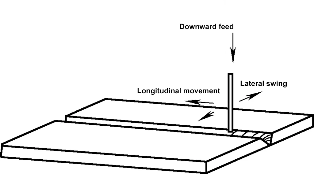
① The purpose of downward feeding of the electrode is to fill the weld seam as the electrode melts and to maintain a continuous arc. When feeding downward, attention should be paid to the effect of arc length on weld quality. An excessively long arc is prone to swinging, causing heat loss and allowing air to enter, resulting in porosity in the weld. A suitable arc length is generally equal to or slightly less than the electrode diameter.
② The lateral swinging of the electrode allows for full fusion of the workpiece edges, widening the weld seam and facilitating the escape of slag and gas from the molten pool, thereby improving weld quality.
③ Longitudinal movement along the weld seam is the main movement for forming the weld. The speed of electrode movement greatly affects the weld formation. If the speed is too fast, melting is insufficient; if too slow, the weld becomes too deep, overheating the workpiece, especially in thin plate welding, which can easily cause burn-through.
The combination of the basic movements in the three directions constitutes electrode manipulation in arc welding. There are many manipulation methods, including linear, reciprocating linear, zigzag, triangular, and circular, as shown in Figure 16.
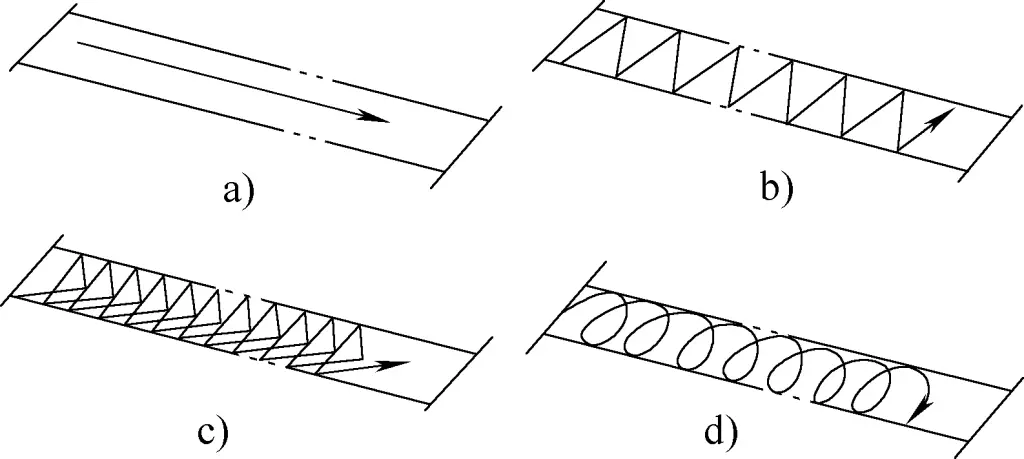
a) Linear
b) Zigzag
c) Triangular
d) Circular
The choice of electrode manipulation method is determined by various factors such as workpiece thickness, weld seam position, joint form, and welding current. In tack welding used in cold work operations, the manipulation mainly involves downward feeding and lateral swinging of the electrode, with a shorter longitudinal movement along the weld seam, having less impact. Therefore, tack welding manipulation is relatively easy to master.
3) Weld seam finishing methods
Finishing the weld seam essentially involves arc striking and finishing operations. Correctly mastering the finishing method can ensure welding quality. The main finishing methods are as follows:
① Circular finishing method.
The electrode makes a circular motion at the finishing point, breaking the arc once the crater is filled, as shown in Figure 17. In tack welding, after igniting the arc, perform circular finishing directly at the weld point to achieve a smooth weld appearance.

② Backward finishing method.
At the finishing point, the electrode remains stationary, lowers the arc, and moves backward while changing the electrode angle, as shown in Figure 18. The electrode moves from position 1 to position 2 in the figure, and once the crater is filled, the arc is broken.

③ Repeated arc breaking finishing method.
During finishing, repeatedly ignite and extinguish the arc several times in a short period until the crater is filled. This method is often used in thin plate welding.
(2) Operations for various welding positions in electrode arc welding
Based on the spatial position of the workpiece joint, welding positions are divided into flat welding, vertical welding, horizontal welding, and overhead welding, which can be distinguished by different weld seam angles and rotation angles.
1) Flat welding
In flat welding, the weld seam can be viewed from above, making it easier to observe the arc and molten pool. The melted electrode drips into the molten pool by gravity, making the welding process easier to control. Therefore, if possible, position the workpiece flat to place the weld seam in a flat welding position. Figure 19 shows the electrode angle during flat welding.

2) Vertical welding
In vertical welding, the molten pool is on a vertical surface, and the molten metal and slag tend to flow downward due to gravity, adding difficulty to the welding operation. Therefore, the electrode specification and welding current selected for vertical welding should be smaller to reduce the molten pool volume, accelerate its cooling, and prevent molten metal from flowing downward. Figure 20 shows the electrode angle during vertical welding.

In vertical welding (including tack welding), the arc striking method is generally used. The operation involves striking the arc on one side of the weld seam, and once the droplet detaches from the electrode, immediately lift the arc to the upper diagonal of the weld seam, then pull the arc to the other side of the weld seam. Pause slightly, wait for the droplet to detach from the electrode, and then lift the arc to the upper diagonal again. Repeat this process to fill the weld seam with droplets, as shown in Figure 21.

During operation, ensure the droplets have sufficient solidification time and try not to break the arc.
3) Horizontal welding
Horizontal welding is also challenging, as the molten metal and slag tend to flow downward under gravity, causing undercut on the upper part of the weld seam and weld bead on the lower part. The electrode angle during horizontal welding is shown in Figure 22.

In horizontal welding, the electrode is inclined 15° in the vertical direction and forms a 70° to 80° angle with the weld seam in the horizontal direction, using a short arc and reciprocating linear manipulation along the weld seam. It is important to select slightly smaller electrode specifications and welding current.
4) Overhead welding
Overhead welding is the most difficult operation among various welding positions because the molten pool is suspended below the weld seam, and gravity significantly affects the droplets, making weld formation difficult.
Overhead welding requires using the shortest possible arc to help droplets adhere to the weld seam. The electrode diameter used in overhead welding is generally ϕ3 to ϕ4mm, and the welding current can be slightly larger to enhance arc force. During overhead welding, the electrode forms a 90° angle with both sides of the workpiece, as shown in Figure 23.

The inclination angle of the electrode relative to the welding direction is determined by the penetration depth. If shallow penetration is required to avoid burn-through, the electrode is inclined about 10° in the opposite direction of welding, as shown in Figure 24.

If a deeper penetration is required, tilt the electrode about 10° in the direction of welding, as shown in Figure 25. The electrode can be moved in a straight line or a reciprocating straight line.

(3) Correct use of electrodes
Proper use of electrodes is one of the important factors to ensure welding quality. The application of commonly used electrodes is shown in Table 5.
Table 5 Application of commonly used electrodes (structural steel electrodes)
| Model | Brand | Coating type | Current type | Main application |
| E4313 | J421 | High titanium potassium type | AC/DC | Used for downward vertical welding and intermittent welding of thin carbon steel plates |
| F4303 | J422 | Titanium calcium type | AC/DC | Welding of more important low carbon steel structures and low alloy steels of the same strength grade |
| E5016 | J506 | Low hydrogen potassium type | AC/DC | Welding of medium carbon steel and some important low alloy steel structures, such as Q345, etc. |
| E5015 | J507 | Low hydrogen sodium type | DC | Welding of medium carbon steel and important low alloy steel structures such as Q345, etc. |
| E5015—G | J507R | Low hydrogen sodium type | DC | Used for welding pressure vessels |
| E5015—G | J507RH | Low hydrogen sodium type | DC | Used for welding important low alloy steel structures, such as ships, high-pressure pipelines, and platforms |
During welding, to ensure welding quality, electrodes must be dried and properly stored. Basic electrode coatings use water glass as a binder, while acidic electrodes use organic materials as binders and wood powder as a gas-forming agent. These factors determine that the drying temperature of electrodes should not be too high. The drying temperatures for different electrodes are shown in Table 6.
Table 6 Drying temperatures of electrodes
| Electrode type | Drying temperature/℃ | Insulation time/h | Maximum drying times | Insulation temperature during use/℃ |
| Basic electrode | 350~400 | 1 | 3 | 100 |
| Acidic electrode | 150 | 1 | 3 | 100 |
| Stainless steel electrode | 220~250 | 1 | 3 | 100 |
| Cellulose type electrode | 100~120 | 1 | 3 | 80~100 |
After drying, electrodes must be placed in an electrode insulation container. After taking out an electrode, the container should be immediately covered to prevent moisture in the air from causing the dried electrode to regain moisture.
5. Safety protection during welding operations
During electrode arc welding operations, safety protection mainly involves preventing electric shock, preventing arc radiation, and ensuring ventilation and dust removal.
(1) Preventing electric shock
There are two types of electric shock accidents in welding operations: direct electric shock, which involves contact with live parts, and indirect electric shock, which involves contact with non-live parts that become live due to insulation damage or equipment failure.
The main forms of direct electric shock during welding include: contact with live parts such as welding tongs and electrodes when replacing electrodes or workpieces; poor insulation between the feet or other body parts and the ground or metal structures, such as welding inside containers, pipelines, in rainy, humid places, or when the body is sweating heavily, which can easily lead to electric shock; contact with exposed live terminals, binding posts, wires, etc., resulting in electric shock; welding near high-voltage power grids, causing breakdown discharge due to excessive proximity.
Indirect electric shock during welding mainly involves equipment leakage, including: equipment leakage due to overload use, internal short circuit heating causing reduced insulation performance; leakage due to coil insulation damage from rain or moisture; leakage due to damage to the insulation part of wires and cables, etc.
Measures to prevent leakage mainly include: strictly following operating procedures; wearing protective gear correctly during welding; reliably grounding the welding equipment shell, so that if shell leakage occurs, the grounding resistance is very small (≤4Ω), forming a loop between the equipment shell and the grounding wire, allowing most of the current to flow through this loop instead of the human body, thus preventing electric shock; selecting qualified wires and cables, and strengthening safety production inspections.
(2) Preventing arc radiation
To prevent the hazards of welding arc radiation and spark burns, it is necessary to wear protective clothing correctly, choose a suitable shade for the working conditions, and set up an arc protection room or screen at the welding site. The screen should be made of flame-retardant materials, with the surface painted black or gray, and the height should not be less than 1.8m, with a 25cm gap at the bottom for air circulation.
Welders should wear cotton canvas work clothes and should not wear synthetic fiber material work clothes. The face shield used should cover the face and ears and should not have light leaks.
(3) Ventilation and Dust Removal
Ventilation and dust removal are important protective measures to prevent the harm of welding fumes and harmful gases to the human body. Therefore, comprehensive and local ventilation should be well implemented.
Comprehensive ventilation is carried out through a mechanical ventilation system with ducts and fans for the entire workshop. It should adopt the method of induced smoke extraction or blow-suction ventilation.
Local ventilation is achieved through local exhaust, where welding fumes and harmful gases are effectively sucked away by the exhaust hood. Local ventilation facilities include smoke hoods, portable small fans, compressed air ejectors, and smoke and dust removal units.
When using local exhaust, the wind speed near the welding work area should be controlled at 30m/min to ensure the arc is not disrupted. Additionally, to meet fire prevention requirements, the distance between flammable and explosive materials and the welding ignition source should not be less than 10m during welding operations.
II. CO2 Gas Shielded Welding
Gas shielded welding, abbreviated as “gas electric welding,” is an arc welding method that uses gas as a protective medium. CO2 gas shielded welding uses CO2 as the shielding gas. It uses welding wire as the electrode, and the arc generated between the welding wire and the workpiece melts the metal, allowing for automatic or semi-automatic welding.
CO2 gas shielded welding has advantages such as low cost, good quality, and high productivity. It is widely used in industries like shipbuilding, automotive, railway vehicles, and agricultural machinery, mainly for welding low carbon steel and low alloy structural steel.
Figure 26 shows the working principle of CO2 gas shielded welding. During welding, CO2 gas is sprayed around the welding wire through the nozzle, forming a local gas shield around the arc, mechanically isolating the droplets and molten pool from the air, ensuring a stable welding process and high-quality welds.

1—Workpiece
2—Weld
3—Molten Pool
4—Arc
5—Nozzle
6—Welding Wire
7—CO2 Protective Gas Flow
In the production and processing of sheet metal components, semi-automatic welding is currently more commonly used, where the welding wire is automatically fed by machinery, and the welder holds the welding torch for operation.
1. Processing Equipment and Tools
The main components of CO2 gas shielded welding equipment are shown in Figure 27. During welding, the welding wire is fed by the wire feeding mechanism 5 through the wire feeding hose 4 and the contact tip 2. CO2 gas is sprayed from the nozzle at a certain flow rate. Once the arc is ignited, the end of the welding wire, arc, and molten pool are surrounded by CO2 gas to prevent the harmful effects of air on the metal.
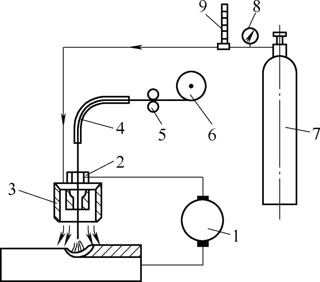
1—Arc Welding Power Source
2—Contact Tip
3—Welding Torch Nozzle
4—Wire Feeding Hose
5—Wire Feeding Mechanism
6—Welding Wire Reel
7—CO2 Gas Cylinder
8—Pressure Regulator
9—Flow Meter
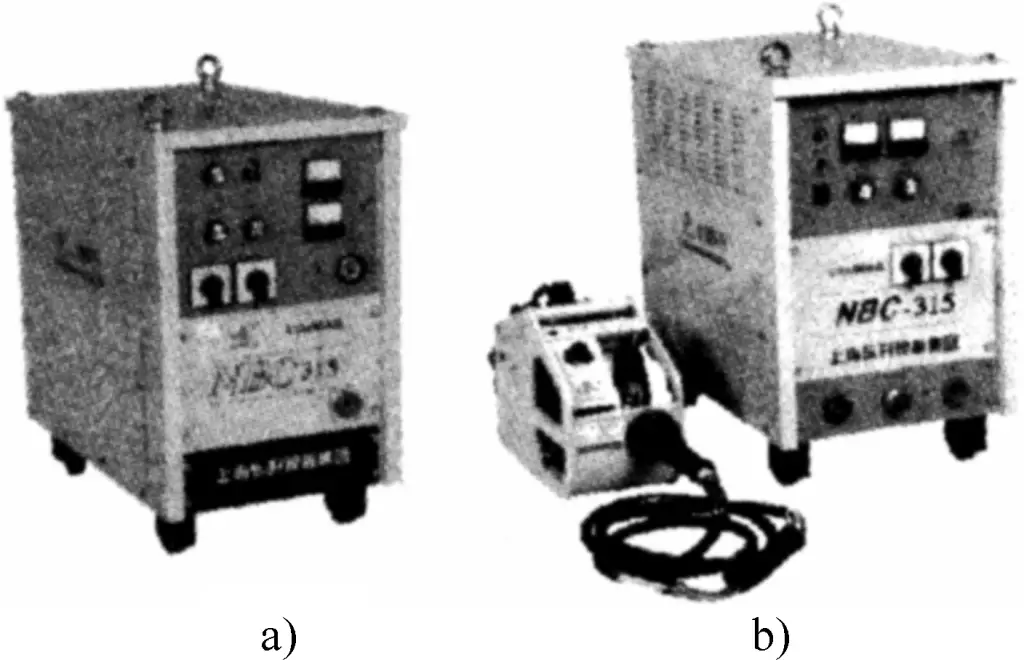
The models of CO2 gas shielded welding machines mainly include NBC—200, NBC—250, NBC—315, NBC—350, NBC—500, etc. The typical appearance of the NBC series CO2 gas shielded welding machines is shown in Figure 28, where Figure 28a shows an integrated welding machine, and Figure 28b shows a split welding machine.
During welding, the welding wire serves as a filler metal or simultaneously as a conductive metal wire. It is a welding material for various welding processes such as gas shielded welding, argon arc welding, and electroslag welding.
The classification of welding wires is usually as follows: ① By welding method, they can be divided into CO2 gas shielded welding wire, tungsten inert gas welding wire, melting inert gas welding wire, submerged arc welding wire, and electroslag welding wire, etc.; ② By shape and structure, they can be divided into solid wire, flux-cored wire, and active wire, etc.; ③ By applicable metal materials, they can be divided into low carbon steel wire, low alloy steel wire, hard alloy surfacing wire, aluminum wire, copper wire, and cast iron wire, etc.
2. Selection of Welding Parameters
Correct selection of welding specifications is crucial for CO2 gas shielded welding. It not only directly affects the quality of the weld but also the amount of metal spatter.
(1) Polarity CO2
In gas shielded welding, to ensure stable arc burning, direct current reverse polarity is generally used, with the workpiece connected to the negative electrode and the welding gun to the positive electrode. Only in surfacing or welding repair of cast steel parts is the positive connection method used.
(2) Arc Voltage
Arc voltage is an important factor affecting droplet transfer, metal spatter, short-circuit frequency, arc burning time, and weld width. In high current welding, the arc voltage is generally 30-50V.
(3) Welding Current
Generally, as the welding current increases, the penetration depth will significantly increase, and the weld width and reinforcement will also increase accordingly. The size of the welding current should be selected based on the thickness of the workpiece, welding wire material, welding wire diameter, weld spatial position, and the required droplet transfer form.
(4) Welding Speed
As the welding speed increases (or decreases), the width, reinforcement, and penetration of the weld will correspondingly decrease (or increase).
(5) Welding Wire Extension Length
The welding wire extension length refers to the length of the welding wire extending out of the contact tip during welding. Generally, for thin wire CO2 gas shielded welding, the extension length is 8-14mm; for thick wire CO2 gas shielded welding, the extension length is 10-20mm.
(6) CO2 Gas Flow Rate
The CO2 gas flow should be selected based on welding current, welding speed, wire extension length, and nozzle diameter. When the welding current is large, the welding speed is fast, and the wire extension is long, the CO2 gas flow should be correspondingly larger. Generally, the CO2 gas flow range is 8 to 25L/min.
Among the above specification parameters, some are basically fixed, such as polarity, wire extension length, and gas flow. Therefore, the selection of CO2 gas shielded welding specifications mainly involves choosing parameters like wire diameter, welding current, arc voltage, and welding speed. The selection of these parameters should be comprehensively considered based on actual conditions such as workpiece thickness, joint form, and welding position. Table 7 shows the commonly used semi-automatic CO2 gas shielded welding specification parameters.
Table 7 Commonly used semi-automatic CO2 gas shielded welding specification parameters
Thickness/mm | Joint form | Assembly gap b/mm | Wire diameter/mm | Welding current/A | Arc voltage/V | Gas flow/(L/min) |
| ≤1.2 |  | ≤0.3 | 0.6 | 30~50 | 18~19 | 6~7 |
| 1.5 | 0.7 | 60~80 | 19~20 | 6~7 | ||
| 2 | 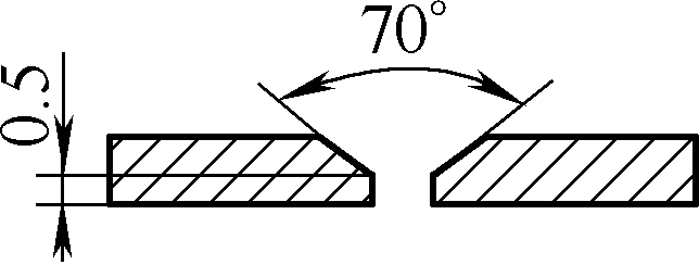 | ≤0.5 | 0.8 | 80~100 | 20~21 | 7~8 |
| 2.5 | ||||||
| 3 | 0.8~0.9 | 90~115 | 21~23 | 8~10 | ||
| 4 | ||||||
| ≤1.2 | 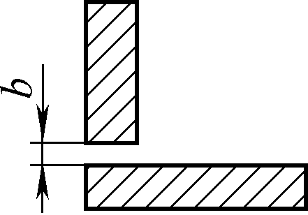 | ≤0.3 | 0.6 | 35~55 | 19~20 | 6~7 |
| 1.5 | 0.7 | 65~85 | 20~21 | 8~10 | ||
| 2 | ≤0.5 | 0.7~0.8 | 80~100 | 21~22 | 10~11 | |
| 2.5 | 0.8 | 90~110 | 22~23 | 10~11 | ||
| 3 | 0.8~0.9 | 95~115 | 21~23 | 11~13 | ||
| 4 | 0.8~0.9 | 100~120 | 21~23 | 13~15 |
3. CO2 gas shielded welding operation techniques
CO2 gas shielded welding operation methods can be divided into leftward welding (see Figure 29a) and rightward welding (see Figure 29b) based on the movement direction of the welding torch (to the left or to the right).
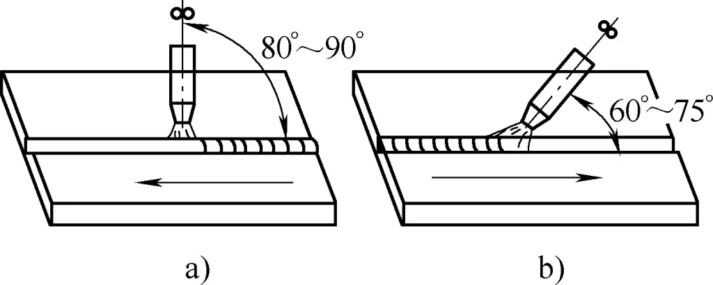
When using the rightward welding method, the visibility of the molten pool and the gas shielding effect are relatively good, but it is inconvenient to observe the seam gap during welding, which can easily lead to welding deviation. Additionally, since the welding wire points directly at the molten pool, the arc has a scouring effect on the molten pool. If not operated properly, it can cause excessive weld bead height, affecting weld formation.
When using the leftward welding method, the nozzle does not block the welder’s view, allowing a clear view of the seam, making it less likely to deviate. It also allows for a larger molten width, resulting in a smooth and aesthetically pleasing weld. Therefore, the leftward welding method is generally used. Meanwhile, the welder must correctly control the angle between the welding torch and the workpiece and the height of the nozzle to maintain a suitable relative position between the torch and the workpiece.
(1) Basic operations of CO2 gas shielded welding
During CO2 gas shielded welding, ensure that the arm holding the torch is in a natural state, and the wrist can flexibly and freely move the torch for various operations. The operating postures for different welding positions in CO2 gas shielded welding are shown in Figure 30.

a) Standing position welding
b) Sitting position welding
c) Leftward welding posture
d) Rightward welding posture
Similar to stick electrode arc welding, arc initiation, arc movement, and arc termination are the most basic operations in CO2 gas shielded welding, but the operation techniques differ from stick electrode arc welding.
1) Arc initiation
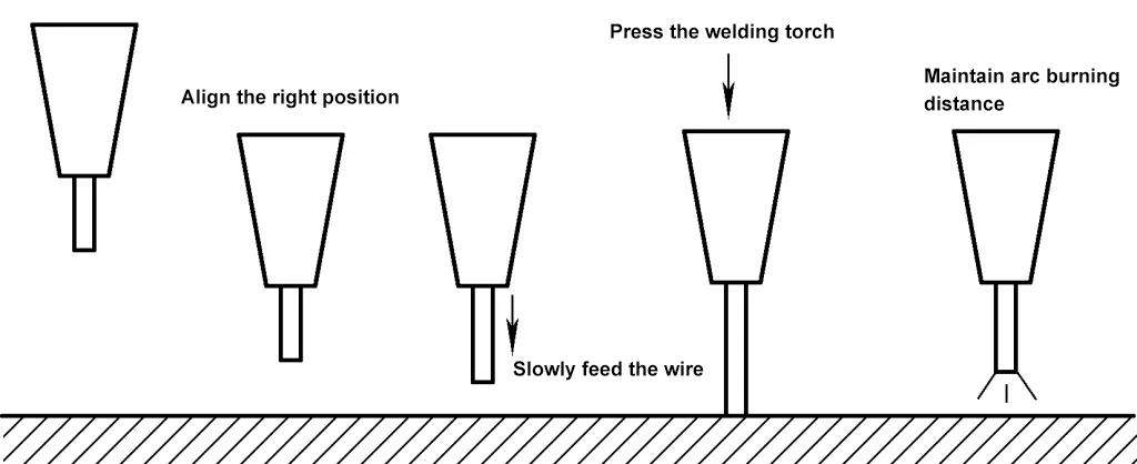
The specific steps for arc initiation are: first, press the jog switch on the remote control box or the control switch on the welding torch to jog out a section of welding wire, ensuring the extended length is less than the distance that should be maintained between the nozzle and the workpiece. Then place the welding torch at the arc initiation point as required (maintaining a suitable angle and nozzle height), ensuring the end of the welding wire does not contact the workpiece, and the nozzle height is determined by the welding current.
If the operation is not proficient, it is best to hold the torch with both hands. Finally, press the control switch on the welding torch, and the welding machine will automatically pre-feed gas and delay power connection. Maintain high voltage, and when the welding wire contacts the workpiece and shorts, the arc will automatically ignite.
During short circuit, the welding torch tends to automatically lift. When initiating the arc, apply slight pressure to the torch to prevent it from lifting too high and extinguishing the arc due to excessive arc length. The entire arc initiation process is shown in Figure 31.
2) Arc movement
To control the width of the weld and ensure fusion quality, CO2 gas shielded welding requires the welding torch to make lateral oscillations similar to stick electrode arc welding. Generally, to reduce heat input and the heat-affected zone and minimize deformation, large lateral oscillations should not be used to achieve a wide weld. Instead, multi-layer multi-pass welding should be used for thick plates. The main oscillation forms and application ranges of the welding torch are shown in Table 8.
Table 8 Main oscillation forms and application ranges of the welding torch
Application range and key points | Oscillation form |
Root pass for thin and medium-thick plates |  |
When there is a gap at the root of thin plates or when the groove has a steel backing plate |  |
Small groove or root pass for medium-thick plates, with a 0.5s pause on both sides of the groove Left and right |  |
Lateral oscillation after the second layer in thick plate welding, with a 0.5s pause on both sides of the groove |  |
First layer in multi-layer welding |  |
When the groove is large, with a 0.5s pause on both sides of the groove |  |
3) Arc termination
CO2 gas shielded welding machines have a crater control circuit. When the welding torch stops advancing at the arc termination point, this circuit is simultaneously activated, causing the welding current and arc voltage to automatically decrease, and power is cut off once the molten pool is filled.
If the welding machine does not have a crater control circuit, or if the crater control circuit is not used due to low welding current, the welding torch stops advancing at the arc termination point and may repeatedly break the arc before the molten pool solidifies. It may be necessary to initiate the arc several times until the crater is filled. Note that the operation should be quick; if the molten pool has solidified before arc initiation, it may result in lack of fusion and porosity defects.
When terminating the arc, pause slightly at the crater, then slowly lift the welding torch. This allows the molten metal to fill the crater and ensures the molten pool metal is still protected by gas before solidification. If the arc termination is too quick, cracks and porosity are likely to occur at the crater.
(2) CO2 shielded welding operations for various plate welding positions
Plate welding positions are divided into flat welding, horizontal welding, and vertical welding, etc. For different welding positions, the following should be noted when performing CO2 gas shielded welding operations.
1) Flat welding
For flat plate butt welding, the leftward welding method is generally used. For thin plate flat butt welding, the welding torch moves in a straight line. If there is a gap, the torch can make appropriate lateral oscillations, but the amplitude should not be too large to avoid affecting the gas shielding effect on the molten pool. For butt welding of medium and thick plate V-grooves, the root pass should use straight-line movement, and the torch can make appropriate lateral oscillations when welding the upper layers.
For fillet welding and lap welding, either the leftward or rightward welding method can be used, but the rightward welding method results in a fuller appearance. During welding, the angle of the welding torch should be controlled based on the plate thickness and weld leg size. For T-joint fillet welding of unequal thickness workpieces, the arc should be biased towards the thicker plate to ensure even heating of both plates.
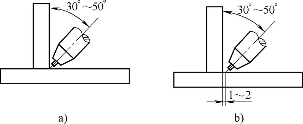
When welding plates of equal thickness, if the weld leg size is less than 5mm, the welding torch can be aimed directly at the corner, as shown in Figure 32a. When the weld leg size is greater than 5mm, the torch needs to be horizontally offset by 1-2mm, while maintaining a 75°-80° angle with the welding direction, as shown in Figure 32b.
2) Vertical and horizontal welding
There are two methods for vertical welding: one is welding from bottom to top, which results in greater weld penetration. By making triangular oscillations during operation, the molten width can be controlled, and weld formation can be improved. This method is generally used for fine wire welding of medium and thick plates. The other method is welding from top to bottom, which is fast and convenient, resulting in a smooth and aesthetically pleasing weld, but with shallow penetration and weaker joint strength, generally used for thin plate welding.
Horizontal welding mostly uses the leftward welding method, with the welding torch making linear movements, or it can make small reciprocating oscillations. Figures 33a and 33b show the relative positions of the welding torch and the workpiece during vertical and horizontal welding, respectively.
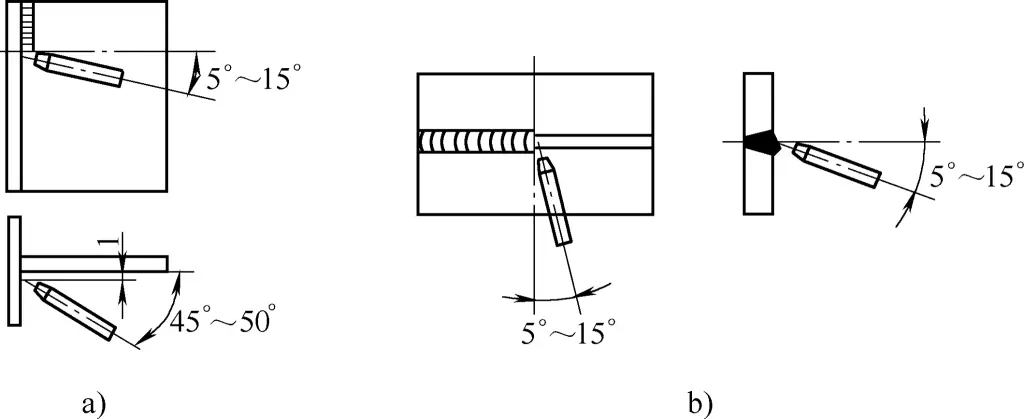
3) Overhead welding
Overhead welding should use thinner welding wire, smaller welding current, and a short arc to increase the stability of the welding process. The CO2 gas flow should also be slightly larger than during flat and vertical welding.
For thin plate overhead welding, small amplitude reciprocating oscillations are generally used. For medium and thick plate overhead welding, appropriate lateral oscillations should be made, and a brief pause should be made on both sides of the seam or groove to prevent the weld bead from bulging in the middle and the liquid metal from flowing down. The spatial position of the welding torch during overhead welding is shown in Figure 34.
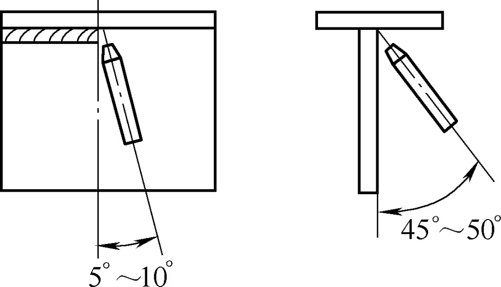
(3) Correct selection of welding wire
Since CO2 is an oxidizing gas, it can decompose into CO and O at high arc temperatures, causing the burning loss of carbon, manganese, silicon, and other alloy elements in the steel. To ensure the alloy elements in the weld, welding wires with higher manganese and silicon content low-carbon steel or alloy steel wires containing corresponding alloy elements should be used. For example, H08MnSiA wire is commonly used for welding low-carbon steel, and H08Mn2SiA wire is commonly used for welding low-alloy structural steel.
Table 9 provides the recommended welding wires for commonly used metal materials when using CO2 gas shielded welding or argon arc welding.
Table 9 Recommended welding wires for commonly used metal materials when using CO2 gas shielded welding or argon arc welding
| Grade | CO2 gas shielded welding | Argon arc welding |
| Q235AF, Q235A, Q235B, Q235C, 20, Q245R | H08MnSi | |
| Q345, Q345R | H08Mn2SiA | H10MnSi |
| 14Cr1MoR | H08Mn2SiA | H08Mn2SiA |
| 12CrMo, 12CrMoG | — | H08CrMoA |
| 15CrMoG, 15CrMoR | — | H13CrMoA |
| 12Cr1MoV, 12Cr1MoVG | — | H08CrMoVA |
| 20Cr13 | — | H02Cr13 |
| 06Cr18Ni10Ti, 12Cr18Ni9 | — | H0Cr21Ni10Ti |
| 06Cr17Ni12Mo2 | — | H0Cr19Ni12Mo2 |
| 06Cr17Ni12Mo2Ti | — | H00Cr19Ni12Mo2 |
| 06Cr19Ni13Mo3 | — | H0Cr20Ni14Mo3 |
| 022Cr19Ni10 | — | H00Cr21Ni10 |
| 06Cr19Ni10 | — | H0Cr21Ni10 |
| 15CrMo | — | H15CrMo, H18CrMoA |
4. Safety protection for CO2 gas shielded welding
Like stick electrode arc welding, CO2 gas shielded welding operations pose three hazards: electric shock, arc radiation, and harmful gases and fumes. Therefore, in addition to complying with the safety protection regulations for stick electrode arc welding, the following safety protection measures should be taken according to the characteristics of CO2 gas shielded welding.
(1) Prevent arc radiation hazards
The arc radiation produced by CO2 gas shielded welding is much stronger and more harmful than that of stick electrode arc welding.
Preventing arc radiation mainly involves preventing the hazards of ultraviolet, infrared, and visible light. Intense ultraviolet exposure can cause dermatitis, resulting in redness and small blisters. Ultraviolet exposure can cause photokeratitis, leading to red eyes, tearing, and stinging. When the eyes are exposed to intense infrared radiation, they can suffer severe burns and pain, and even retinal burns.
The visible light of the welding arc is about ten thousand times stronger than the normal light intensity that the naked eye can bear. When exposed to the visible light of the arc at close range, the human eye cannot see the surrounding objects, commonly known as “dazzling.”
To prevent arc radiation hazards, the following measures should be taken:
① Welders should not expose their skin, and should carefully check for any exposed skin before welding;
② In workplaces with dense welders, light-blocking barriers should be set up between them.
(2) Prevent burns and fires
The spatter situation in CO2 gas shielded welding is more severe than in stick electrode arc welding. During welding, one must protect themselves from burns and prevent fires. To prevent burns and fires, the following measures should be taken:
① According to the site conditions, welders should ensure they are in the best position to avoid being burned by spatter;
② Before welding, carefully observe the welding area and surrounding environment (where spatter may fall) for flammable and explosive materials, and do not weld if the situation is unclear;
③ After work, carefully check the workplace and surroundings for any remaining flames, and only leave after confirming safety.
(3) Prevent harmful gases and fumes hazards
Common harmful gases during CO2 gas shielded welding include CO2, CO, NO2, etc. When using flux-cored wires, more fumes are emitted, and the composition is more complex. Long-term inhalation can lead to occupational diseases such as pneumoconiosis and manganese poisoning. Therefore, the following protective measures must be taken:
① Welders should enhance personal protection awareness and wear dust masks;
② During work, welders should be in the “upwind” position to reduce the invasion of harmful gases;
③ Strengthen ventilation and dust removal measures.
(4) Safe use of CO2 gas cylinders
When performing CO2 gas shielded welding, the relevant regulations for gas cylinder safety supervision must be followed, mainly in the following aspects:
① CO2 gas cylinders must be inspected and have the steel stamp mark of the gas cylinder manufacturer, and the inspection steel stamp on the neck of the cylinder should indicate that the cylinder is within the allowable period;
② It is best to use a frame when hoisting CO2 gas cylinders to prevent them from falling from a height;
③ CO2 gas cylinders should be used upright and have positioning measures to prevent them from falling and causing injury;
④ CO2 gas cylinders should have sunshade measures to prevent sun exposure;
⑤ The gas in CO2 gas cylinders should not be exhausted, and the remaining pressure should not be less than 1MPa.
III. Argon arc welding
Argon is an inert gas, which neither reacts chemically with metals nor dissolves in liquid metals, thus effectively preventing the harmful effects of air on the molten pool.
Argon arc welding uses argon as a protective gas, making it suitable for welding various alloy steels, easily oxidized non-ferrous metals, and rare metals such as zirconium, tantalum, and molybdenum. Because the arc burns in a compressed airflow, the heat is concentrated, the molten pool is small, the welding speed is fast, the heat-affected zone is narrow, and the workpiece deformation after welding is small.
Argon arc welding can be used for almost all metals and alloys. Currently, it is mainly used for welding aluminum, magnesium, titanium and their alloys, low alloy steel, heat-resistant steel, stainless steel, etc. It is more difficult to weld metals with low melting points and easy evaporation (such as lead, tin, zinc). Due to the high cost of argon, the equipment and control system for argon arc welding are relatively complex, and to prevent the protective gas flow from being disrupted, argon arc welding can only be performed indoors.
Argon for welding is generally transported in steel cylinders, which are painted gray with the words “Pure Argon” in dark green on the outside. The presence of oxygen, nitrogen, carbon dioxide, or moisture in argon can reduce its protective effect and cause defects such as slag inclusions and gas pores. Therefore, when welding aluminum, magnesium, and their alloys, the purity of argon should not be less than 99.9% (mass fraction); when welding stainless steel, heat-resistant steel, copper, and their alloys, the purity of argon should not be less than 99.7% (mass fraction).
Argon arc welding is divided into two types: consumable electrode argon arc welding and tungsten electrode argon arc welding (see Figure 35).
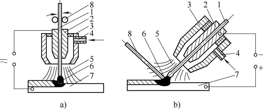
a) Consumable electrode argon arc welding
b) Tungsten electrode argon arc welding
a) In the figure:
1—Welding wire
2—Contact tip
3—Nozzle
4—Inlet pipe
5—Argon flow
6—Arc
7—Base material
8—Wire feed roller
b) In the figure:
1—Tungsten electrode
2—Contact tip
3—Nozzle
4—Inlet pipe
5—Argon flow
6—Arc
7—Base material
8—Filler wire
Consumable electrode argon arc welding uses a consumable metal wire as the electrode, which also serves as the filler material during welding. It can be divided into automatic and semi-automatic forms. In semi-automatic welding, the welder operates the torch (welding gun) manually. Consumable electrode argon arc welding allows the use of larger currents and is suitable for welding thicker workpieces.
Tungsten electrode argon arc welding uses tungsten or tungsten alloy as the electrode. During welding, an arc is generated between the tungsten electrode and the workpiece. Since the tungsten electrode does not melt, it is also called non-consumable electrode argon arc welding. Tungsten electrode argon arc welding requires additional filler wire to be melted into the weld pool. Due to the high melting point of the tungsten rod used as the electrode, and the slow consumption of the tungsten electrode, it is easy to mechanize. However, the current-carrying capacity of the tungsten electrode is limited, so it is only suitable for welding thin workpieces.
Tungsten electrode argon arc welding can be divided into automatic and manual forms. Figure 36 shows a schematic diagram of the equipment composition for manual tungsten electrode argon arc welding. The equipment can be divided into the welding power system, control system, gas supply system, and torch.
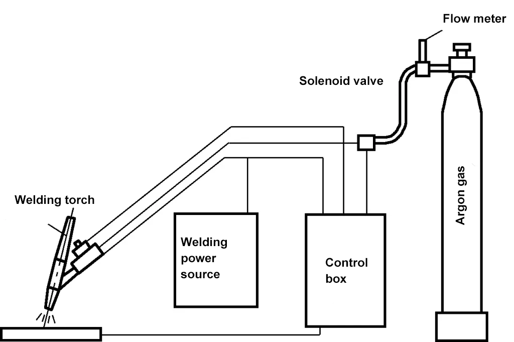
The thickness range of the plates welded by tungsten electrode argon arc welding is preferably below 3mm from a productivity perspective. For certain thick-walled important components (such as pressure vessels and pipelines), argon arc welding is often used for the root pass to ensure the quality of the root weld during full-position welding and narrow gap welding.
Different metal materials require different types and polarities of current when performing tungsten electrode argon arc welding. Aluminum, magnesium, and their alloys generally use alternating current, while other metals are welded using direct current with positive connection.
Direct current tungsten electrode argon arc welding uses direct current without polarity changes, resulting in a very stable arc. However, it has positive and negative polarities. When the workpiece is connected to the positive terminal of the power supply and the tungsten electrode to the negative terminal, it is called the positive connection method; the reverse is called the reverse connection method.
Using the direct current positive connection method, the tungsten electrode burns very little, and the arc is relatively stable, but it cannot remove the oxide film on the metal surface. Except for aluminum and magnesium alloys, other metal surfaces do not have high melting point oxide film issues, so this connection method is generally used for welding other metals. The direct current reverse connection method is rarely used in actual production.
Alternating current tungsten electrode argon arc welding current polarity changes periodically, equivalent to half-wave direct current positive connection and half-wave direct current reverse connection in each cycle. During the positive connection half-wave, the tungsten electrode can emit enough electrons without overheating, which is beneficial for arc stability; during the reverse connection half-wave, the oxide film generated on the workpiece surface can be easily removed, resulting in a bright and aesthetically pleasing weld with good formation.
This way, it simultaneously considers the cathodic cleaning effect and the benefits of low tungsten electrode burn-off and good arc stability. Alternating current argon arc welding is generally chosen for metals with high reactivity, such as aluminum, magnesium, and their alloys, as well as aluminum bronze.
When welding with tungsten electrode argon arc welding, the correct relative position between the torch, filler wire, and workpiece must be maintained (see Figure 37). The distance between the nozzle end of the torch and the workpiece should be controlled between 8-14mm. The greater the distance, the worse the gas shielding effect, but if the distance is too close, it will affect the welder’s vision and easily cause the tungsten electrode to contact the weld pool and short circuit, resulting in tungsten inclusions.
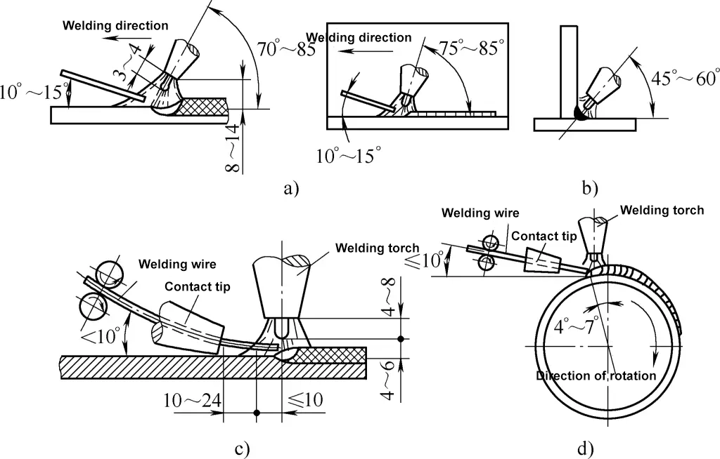
a) Butt argon arc welding
b) Corner argon arc welding
c) Flat butt automatic argon arc welding
d) Circumferential seam automatic argon arc welding
Straight seam welding usually uses the leftward welding method. The angle between the filler wire and the workpiece should not be too large, otherwise it will disturb the stability of the arc and gas flow. In manual tungsten electrode argon arc welding, the filler wire can be fed intermittently or continuously, but it is essential to prevent the filler wire from contacting the high-temperature tungsten electrode to avoid contamination, burn-off, and damage to arc stability.
Additionally, when feeding the wire intermittently, it is necessary to prevent the end of the filler wire from moving out of the gas protection zone and becoming oxidized. When using circumferential seam automatic tungsten electrode argon arc welding, the torch should be offset from the workpiece centerline in the opposite direction of rotation to facilitate wire feeding and ensure good weld formation.
The welding wire for argon arc welding is usually selected based on the chemical composition of the base material and the mechanical properties of the weld. Sometimes strips of the base material can be used as filler wire for manual tungsten electrode argon arc welding.
For commonly used metal materials, the recommended welding wire for argon arc welding can be found in Table 9.
IV. Selection of welding methods for commonly used metal materials
Welding processes can be divided into three main categories based on their technological characteristics and the state of the base metal: fusion welding, pressure welding, and brazing.
Fusion welding is a method that uses local heating to heat the joint of the workpieces to a molten state, allowing them to fuse together and bond after cooling. It mainly includes arc welding, gas welding, plasma arc welding, electron beam welding, etc.
Pressure welding involves applying a certain pressure to the joint surfaces of two workpieces, whether heated or not, to promote atomic bonding and achieve a strong connection between the workpieces. It mainly includes resistance welding, friction welding, high-frequency welding, etc.
Brazing involves heating both the filler metal, which has a lower melting point than the workpieces, and the workpieces themselves, causing the filler metal to melt (while the workpieces do not). The liquid filler metal wets the workpieces and fills the joint gap, achieving a solid-state bond between the welded metals upon cooling. It mainly includes soldering, copper brazing, etc.
According to the current level of welding technology, most metal materials used in industry are weldable, although the ease of welding varies. The recommended welding methods for commonly used metal materials can be selected by referring to Table 10.
Table 10 Recommended welding methods for commonly used metal materials
Metals and Alloys | Welding Methods | |||||||||||||
| Electrode Arc Welding | Submerged Arc Welding | CO2 Gas Protection Welding | Argon Arc Welding | Electroslag Welding | Gas Electric Welding | Oxyacetylene Welding | Pressure Welding | Spot Seam Welding | Flash Welding | Thermite Welding | Electron Beam Welding | Brazing | ||
| Carbon Steel | Low Carbon Steel | A | A | A | B | A | A | A | A | A | A | A | A | A |
| Medium Carbon Steel | A | A | A | B | A | A | A | A | B | A | A | A | B | |
| High Carbon Steel | A | B | C | B | B | B | B | A | D | A | A | A | B | |
| Tool Steel | B | B | D | B | C | C | A | A | D | B | B | A | B | |
| Copper Steel | A | A | C | B | A | A | A | A | A | A | B | A | B | |
| Cast Steel | Carbon Cast Steel | A | A | A | B | A | A | A | B | B | A | A | A | B |
| High Manganese Steel | B | B | B | B | A | A | B | D | B | B | B | A | B | |
| Cast Iron | Gray Cast Iron | B | D | D | B | B | B | A | D | D | D | B | C | C |
| Malleable Cast Iron | B | D | D | B | B | B | B | D | D | D | B | C | C | |
| Alloy Cast Iron | B | D | D | B | B | B | A | D | D | D | A | C | C | |
| Low Alloy Gold Steel | Nickel Steel | A | A | C | B | D | D | A | A | A | A | B | A | B |
| Nickel Copper Steel | A | A | C | One | D | D | A | A | A | A | B | A | B | |
| Manganese Molybdenum Steel | A | A | C | — | D | B | A | B | A | A | B | A | B | |
| Carbon Molybdenum Steel | A | A | C | — | D | B | A | B | — | A | B | A | B | |
| Nickel Chromium Steel | A | A | C | — | D | D | A | A | D | A | B | A | B | |
| Chromium Molybdenum Steel | A | A | C | B | D | D | A | A | D | A | B | A | B | |
| Nickel Chromium Molybdenum Steel | B | A | C | B | D | D | B | A | D | B | B | A | B | |
| Nickel Molybdenum Steel | B | B | C | A | D | D | B | B | D | B | B | A | B | |
| Chromium Steel | A | B | C | — | D | D | A | A | D | A | B | A | B | |
| Chromium-vanadium steel | A | A | C | — | D | D | A | A | D | A | B | A | B | |
| Manganese steel | A | A | C | B | B | B | A | B | D | A | B | A | B | |
| Stainless Steel | Chromium steel horse Martensitic type | A | A | B | A | C | B | B | B | C | B | D | A | C |
| Chromium steel iron Ferritic type | A | A | B | A | C | B | B | B | A | A | D | A | C | |
| Chromium-nickel steel austenitic Body type | A | A | B | A | C | B | A | A | A | A | D | A | B | |
| Heat resistant Alloy | Heat-resistant superalloy | A | A | C | A | C | C | A | B | A | A | D | A | C |
| High nickel alloy | A | A | C | A | C | C | A | B | A | A | D | A | B | |
| Light metal Category | Pure aluminum | B | D | D | A | D | D | A | C | A | A | D | A | B |
| Non-heat-treatable Wrought aluminum alloy | B | D | D | A | D | D | A | C | A | A | D | A | B | |
| Heat-treatable Aluminum alloy | B | D | D | B | D | D | B | C | A | A | D | A | C | |
| Pure magnesium | D | D | D | A | D | D | B | C | A | A | D | B | B | |
| Magnesium alloy | D | D | D | A | D | D | B | C | A | A | D | B | C | |
| Pure titanium | D | D | D | A | D | D | D | D | A | D | D | A | C | |
| Titanium alloy | D | D | D | A | D | D | D | D | B | D | D | A | D | |
| Copper alloy | Pure copper | B | C | C | A | D | D | B | C | C | C | D | B | B |
| Brass | B | D | C | A | D | D | B | C | C | C | D | B | B | |
| Phosphor bronze | B | C | C | A | D | D | C | C | C | C | D | B | B | |
| Aluminum bronze | B | D | C | A | D | D | C | C | C | C | D | B | B | |
| Nickel bronze | B | D | C | A | D | D | C | C | C | C | D | B | B | |
| Zirconium, niobium | D | D | D | B | D | D | D | D | B | D | D | B | C | |
Note: In the table, A—most suitable, B—suitable, C—slightly suitable, D—not suitable.
V. Riveting
Riveting is a method of operation that connects two or more parts into a non-detachable whole using rivets. The riveting process is shown in Figure 38. During riveting, the rivet is inserted into the rivet holes of the two workpieces to be connected, and the rivet head is pressed tightly against the surface of the workpiece. Then, pressure is applied to upset the part of the rivet protruding from the workpiece surface to form a rivet head, thus connecting the two workpieces.

1—Rivet shank
2—Original rivet head
3—Riveted rivet (rivet head)
Although the use of riveted structures is decreasing with the continuous advancement of welding technology, riveting has the advantages of simple processing technology, reliable connection, vibration resistance, impact resistance, and toughness and plasticity higher than welding. Therefore, riveting is still widely used in the connection of dissimilar metals and in some heavy-duty steel structures that frequently bear dynamic loads.
1. Types and uses of rivets
Rivets are the most basic connecting components in riveted structures. They consist of a cylindrical rivet shank, a rivet head, and an upset head. There are many types of rivets. In steel structure connections, common rivet forms include round head rivets, flat cone head rivets, countersunk head rivets, semi-countersunk head rivets, flat head rivets, flat round head rivets, and flat flat head rivets.
Among them, round head rivets, flat cone head rivets, and flat head rivets are used for strong riveting; flat round countersunk head rivets are used in places where the surface of the riveted area has slight protrusions to prevent slipping or for the connection of non-metallic materials; countersunk head rivets are used for riveting where a smooth workpiece surface is required.
When selecting rivets, the material of the rivet should be the same as that of the riveted parts and should have good plasticity. Common steel rivet materials include Q195, Q235, 10, 15, etc.; copper rivets include T3, H62, etc.; aluminum rivets include 1050A, 2A01, 2A10, 5B05, etc. Common types and uses of rivets are shown in Table 11.
Table 11 Common types and uses of rivets
Name | Diagram | Standard | Rivet shank | General use | |
| d/mm | L/mm | ||||
Round head rivet | 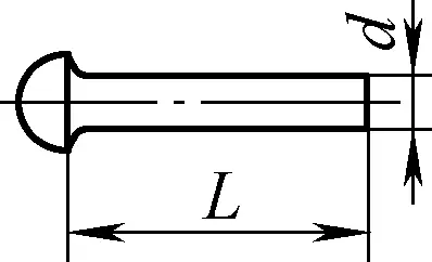 | GB863.1—1986 (Rough) | 12~36 | 20~200 | Rivet seams bearing large lateral loads in boilers, roof trusses, bridges, vehicles, etc. |
| GB/T 867—1986 | 0.6~16 | 1~100 | |||
Flat cone head rivet | 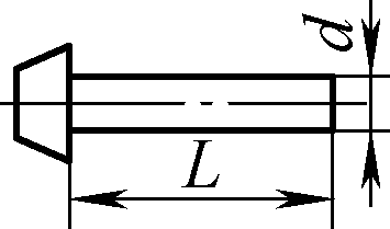 | GB/T 864—1986 (Rough) | 12~36 | 20~200 | Large head, corrosion-resistant, used in ships, boilers |
| GB 868—1986 | 2~16 | 3~110 | |||
Countersunk head rivet | 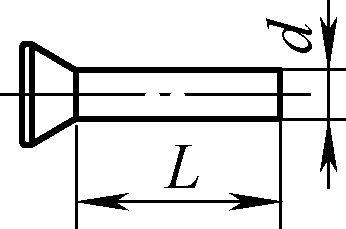 | GB 865—1986 (Rough) | 12~36 | 20~200 | Structures bearing large forces, and requiring rivets not to protrude or not fully protrude from the workpiece surface |
| GB/T 869—1986 | 1~16 | 2~100 | |||
Countersunk rivet | 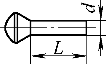 | GB 866—1986 (Coarse) | 12~36 | 20~200 | |
| GB/T 870—1986 | 11~6 | 2~100 | |||
Flat head rivet | 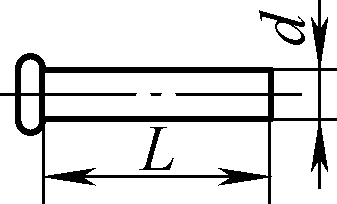 | GB/T 872—1986 | 2~10 | 1.5~50 | Connection of thin plates and non-ferrous metals, suitable for cold riveting |
Flat round head rivet | 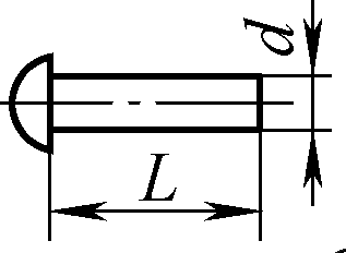 | GB/T 871—1986 | 1.2~10 | 1.5~50 | |
In addition, hollow or open rivets shown in Figure 39 are also commonly used in small structures.

a) Semi-hollow type
b) Hollow type
c) Open type
d) Press-fit
e) Threaded type
f) Drilled-through type
When semi-hollow rivets are properly assembled, they essentially become solid components because the hole depth is just enough to form the rivet head, so they are mainly used for connections where the riveting head pressure is not very high. Hollow rivets are used for riveting fiber, plastic sheets, or other soft materials.
2. Key points and precautions for riveting operations
According to the different riveting temperatures, riveting can be divided into hot riveting and cold riveting. The main methods of riveting are manual riveting and mechanical riveting. Generally, rivets made of non-ferrous metals and light metals with good plasticity, such as copper and aluminum, are usually cold riveted. The maximum diameter for cold riveting steel rivets is generally ϕ8mm for hand riveting, ϕ13mm for rivet gun riveting, and ϕ20mm for riveting machine riveting.
When riveting Q345 high-strength low-alloy structural steel and larger diameter rivets, hot riveting is required, which involves heating the rivet to a certain temperature before riveting. The heating temperature for hot riveting rivets is 1000-1300℃, and the termination temperature should not be lower than 500℃ to prevent the rivet temperature from dropping to the material’s blue brittle temperature range, which could cause cracks during riveting.
(1) Manual riveting operation
Manual riveting is usually used for cold riveting small rivets, but it can also replace other riveting methods when equipment conditions are poor. The key to manual riveting is that after the rivet is inserted into the hole, the rivet head should be tightly pressed, and then the protruding rivet shank should be hammered (rivet hammer) into a rough cap shape or flattened.
If it is hot riveting, a cover mold with a shape similar to the rivet head should be used, and a sledgehammer should be used to strike the cover mold while continuously rotating it until the rivet is properly riveted.
1) Riveting of semi-round head rivets
Figure 40 shows the riveting process of semi-round head rivets.
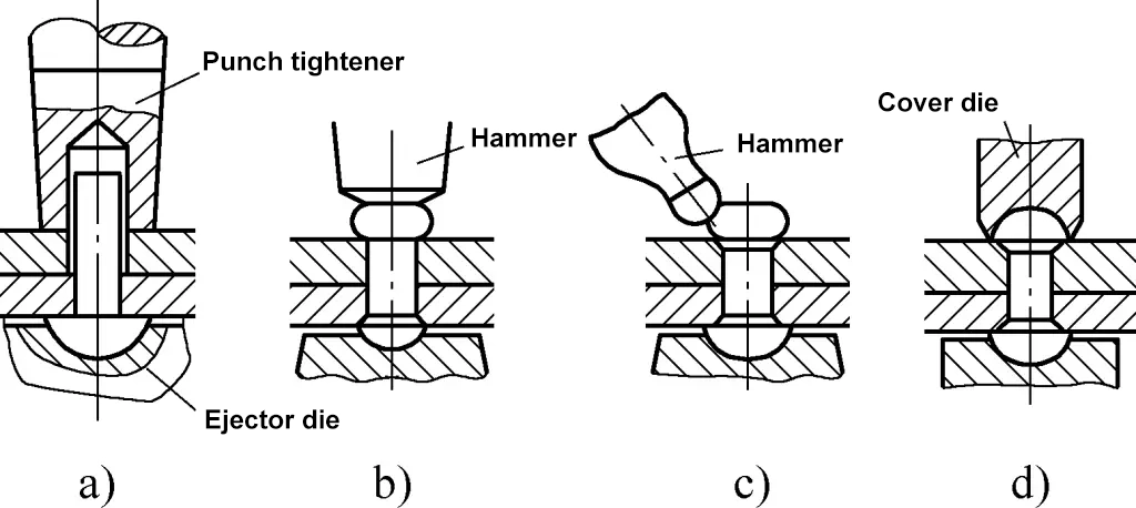
Before riveting, the workpiece should be cleaned, ensuring that the parts to be riveted are flat and smooth, and burrs on the contact surface edges and rust, oil stains, etc., on the contact surface should be removed.
During riveting, the workpiece to be riveted should be tightly fitted after drilling, the rivet should be inserted from below the workpiece into the hole, supported by the spherical pit of the top mold, and the workpiece should be pressed tightly. Hammer the pressing punch to compact the connecting piece (see Figure 40a); then use a hammer to strike the protruding part of the rivet to fill the hole and thicken the shank head (see Figure 40b); use the hammer to strike the periphery of the thickened part at an appropriate angle (see Figure 40c); finally, use a cover mold to trim and shape (see Figure 40d).
2) Riveting of countersunk rivets
Like the riveting of semi-round head rivets, the workpiece should be cleaned before riveting countersunk rivets. There are two types of countersunk rivets: one is ready-made countersunk rivets, and the other is made by cutting round steel to the required length as rivets.
During riveting, insert the cut round steel into the hole, press the connecting piece tightly, thicken the protruding parts of both ends of the rivet, rivet the second surface first, then the first surface, and finally smooth the protruding parts. This method is not easy to compact the connecting piece and is rarely used.
3) Riveting of hollow rivets
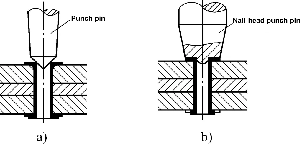
The riveting process of hollow rivets is shown in Figure 41. Similarly, after cleaning the workpiece, insert the rivet into the workpiece hole, and press the rivet head tightly below. First, use a conical punch to press once to open the rivet mouth and fit it tightly to the workpiece hole (see Figure 41a), then use a special punch with a flat edge to rotate and strike, making the rivet mouth fit flat to the workpiece hole (see Figure 41b).
4) Tight and secure riveting
Although rivets can be fitted with sealant, their joints are not sealed against water and gas. For components requiring tight and secure riveting, in addition to performing riveting operations as described above, the end face seams of rivets or riveted parts should be reinforced and secured, commonly using the methods of caulking rivets and caulking seams.
① Caulking rivets
If there is a cap on the rivet head as shown in Figure 42, the cap should be cut off first with an edge chisel (the cutting groove depth should be less than 0.5mm), and then the rivet head should be caulked around with a caulking chisel to make it fit tightly with the board surface.

② Caulking seams
Use a caulking chisel to create a 75° bevel at the seam of the end face of the riveted part to make the seam tight, as shown in Figure 43.

(2) Mechanical riveting operation
Mechanical riveting mainly includes pneumatic riveting and hydraulic riveting. Pneumatic riveting uses compressed air as power to drive the piston block in the cylinder to reciprocate, striking the punch installed on the piston rod to complete the riveting work under rapid hammering. Hydraulic riveting uses hydraulic principles for riveting and is divided into fixed and mobile types.
Fixed hydraulic riveting machines are generally only used for riveting specialized products, equipped with automatic feeding and discharging devices, thus having high production efficiency and low labor intensity, mainly suitable for riveting large batches of standardized products; mobile hydraulic riveting machines are equipped with front and rear, left and right movement devices, and even up and down lifting devices according to product needs, making it a relatively ideal riveting method at present.
Due to the fast speed of mechanical riveting, during hot riveting, to ensure that the rivet temperature after riveting is not too high, which would reduce strength and affect riveting quality, the heating temperature for mechanical riveting should be around 800℃, not too high. Otherwise, the rivet temperature at the end of riveting would be too high, and the strength would not meet the requirements, reducing the quality of the rivet joint.
If necessary, water can be poured on both sides of the rivet, using artificial forced cooling methods to quickly reduce the temperature, increase strength, shorten cooling time, and reduce the chance of annealing of the rivet head due to heat.
(3) Key points of the riveting process
The key points of the riveting process are the prerequisites for ensuring riveting quality. Any problem in the following items will affect the quality of riveting.
1) Determination of rivet diameter d
During riveting, if the rivet diameter is too large, it is difficult to form the rivet head, which can easily deform the sheet material; if the rivet diameter is too small, the rivet strength is insufficient, increasing the number of rivets, which is inconvenient for processing.
The choice of rivet diameter d is mainly determined based on the thickness t of the riveted parts, and the thickness t of the riveted parts is determined according to the following three principles: ① When overlapping plates, if the plate thicknesses are similar, calculate based on the thicker plate; ② When there is a large difference in plate thickness, calculate based on the thinner one; ③ When riveting sheet material and profile, calculate based on the average thickness of both.
Generally, the total thickness of the riveted parts should not exceed 4 times the diameter of the rivet. The diameter d of the rivet can be calculated using the following formula, but in mass production, a trial rivet correction should be conducted in advance.
d=√(50t-4)
In the formula
- t – thickness of the riveted part (mm);
- d – diameter of the rivet (mm).
Additionally, the diameter d of the rivet can also be determined by referring to Table 12.
Table 12 Selection of rivet diameter d (unit: mm)
| Plate thickness | d |
| 5~6 | 10~12 |
| 7 | 14~18 |
| 9.5~12.5 | 20~22 |
| 13~18 | 24~27 |
| 19~24 | 27~30 |
| ≥25 | 30~36 |
2) Determination of rivet length L
During riveting, if the rivet shank is too long, it will result in an oversized or overly high rivet head, and the rivet shank is prone to bending during the riveting process; if the rivet shank is too short, the rivet head will be too small, affecting the strength of the rivet. The required length L of the rivet should be determined based on the total thickness ∑t of the riveted parts and the portion reserved for the rivet head. The rivet length L can be calculated using the following formula:
L=1.1∑t+1.4d (semi-circular head)
L=1.1∑t+1.1d (semi-flush head)
L=1.1∑t+0.8d (flush head)
In the formula
- ∑t – total thickness of the riveted parts (mm);
- d – diameter of the rivet (mm).
3) Determination of rivet hole diameter d0
The fit between the rivet hole diameter d0 and the rivet diameter d must be appropriate. If the hole diameter is too large, the rivet shank is prone to bending during riveting, affecting the quality of the rivet; if the hole diameter is equal to or smaller than the rivet diameter, it will be difficult to insert the rivet into the hole during riveting, or it may cause an uneven surface on the plate, or even damage the plate due to rivet expansion.
Generally speaking, during cold riveting, the rivet hole diameter d0 is close to the rivet shank diameter d, while when riveting angle steel and plates, the hole diameter should be increased by 2%; during hot riveting, d0 is slightly larger than d; when riveting multilayer plates, the hole should be drilled and then reamed (leaving a reaming allowance of 0.5~1mm). The rivet hole diameter can be selected by referring to Table 13.
Table 13 Rivet hole diameter d0 (unit: mm)
| Rivet diameter d | 2 | 2.5 | 3 | 3.5 | 4 | 5 | 6 | 8 | 10 | 12 | |
| d0 | Fine fit | 2.1 | 2.6 | 3.1 | 3.6 | 4.1 | 5.2 | 6.2 | 8.2 | 10.3 | 12.4 |
| Coarse fit | 2.2 | 2.7 | 3.4 | 3.9 | 4.5 | 5.6 | 6.5 | 8.6 | 11 | 13 | |
| Rivet diameter d | 14 | 16 | 18 | 20 | 22 | 24 | 27 | 30 | 36 | ||
| d0 | Fine fit | 14.5 | 16.5 | ||||||||
| Coarse fit | 15 | 17 | 19 | 21.5 | 23.5 | 25.5 | 28.5 | 32 | 38 | ||
(4) Precautions for riveting operations
Riveting is a permanent connection. If disassembly is necessary during maintenance, the rivet should be drilled out and replaced. If it is required to ensure that the dimensional deviation of the connected workpiece is less than ±0.03mm, riveting should not be used.
The quality of riveting can be inspected using visual inspection, hammer testing, templates, chalk lines, or a combination of these methods.
The visual inspection method mainly checks the quality and defects of the rivet surface, such as whether the rivet head is too large or too small, and whether there are cracks, misalignment, or surface damage. Tapping the rivet head with a small hammer and listening to the sound it makes is a basic method to check whether the rivet is tight enough.
If, upon inspection, a rivet is found not to meet the requirements, it should be removed and re-riveted. The removal method is to use a portable pneumatic drill to drill out the rivet head, but it should not affect the size of the rivet hole. If two re-riveting attempts do not meet the requirements, the rivet hole cannot be riveted according to the original diameter, and a larger diameter rivet should be selected for re-riveting to ensure the quality of the rivet.
In addition, during riveting operations, safety and civilized production requirements must be followed, and attention should be paid to the following:
1) Maintain a clean working environment with sufficient operating space. The placement of workpieces and tools should have designated locations and be neatly arranged. During work, personal protective equipment should be worn completely.
2) During hot riveting, the heating furnace should have good fire prevention, dust removal, and smoke exhaust facilities. After each use, extinguish any remaining fire and clean up thoroughly. When throwing and catching heated rivets, the necessary tools should be complete, and operators should coordinate and master the correct throwing and catching techniques.
3) When using a rivet gun for riveting, it is strictly forbidden to point the muzzle at people. When not in use, the cover mold inserted in the gun barrel must be removed, and it should be put on and taken off as needed, cultivating good operating habits.
4) During manual riveting, the operation method of the hammer should be mastered; when reshaping with a cover mold, care should be taken to prevent mis-hits that could cause the cover mold to bounce and injure someone.
VI. Seaming
The method of connecting by folding and interlocking the edges of two thin plates and pressing them tightly (manual seaming is hammer-tightened) is called seaming, also known as seam folding or seam locking. Seaming has relatively high strength and can replace soldering, and it also has a certain degree of sealing, making it widely used, especially suitable for connecting thin plates within 1mm.
1. Structural forms of seaming
There are many structural forms of seaming, and Table 14 lists the commonly used seaming forms.
Table 14 Common seaming forms
Name | Corner seam | |||||
Half lock | Single lock | Double lock | ||||
Diagram | 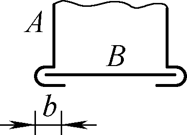 | 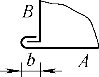 | 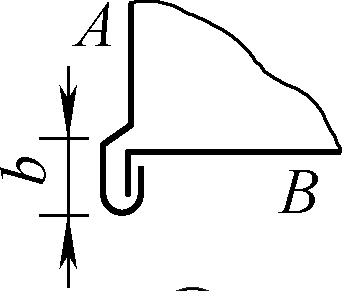 | 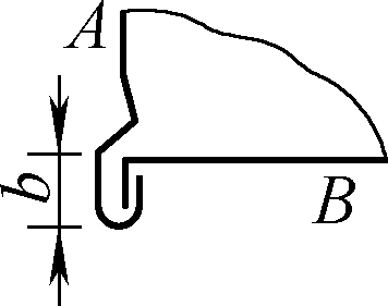 | 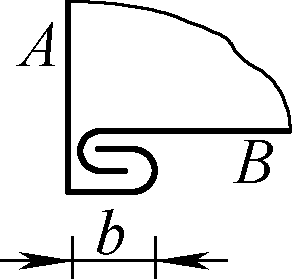 | 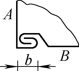 |
Allowance coefficient K | KA=2, KB=1 | |||||
Description | See notes 1~4 | |||||
Name | Corner seam | Flat seam | ||||
Snap | Cone buckle (Pittsburgh buckle) | Hanging buckle | Single buckle | Inner flat single buckle | Outer flat single buckle | |
Simple diagram | 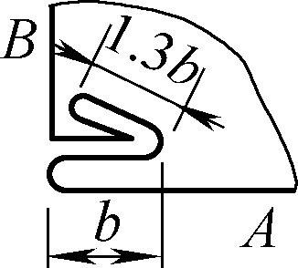 | 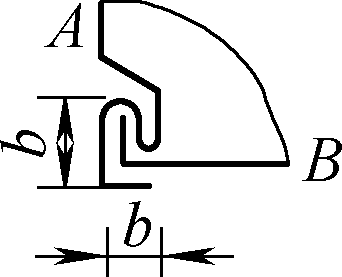 | 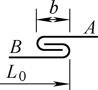 | 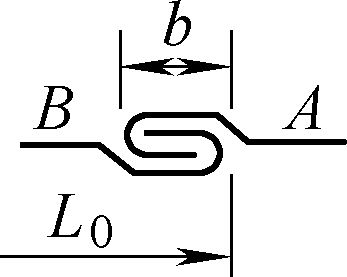 |  |  |
Allowance coefficient K | KA=2.5, KB=1.5, KA=3, KB=1 | KA=2, KB=1 | ||||
Description | See notes 1~4 | See notes 5~7 | See notes 6, 7 | |||
Name | Flat seam | Standing seam | |||
Double lock | Compound lock | Sleeve lock | Single lock | Double lock | |
Simple diagram | 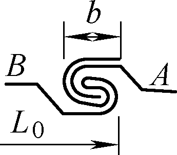 | 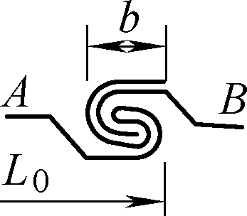 | 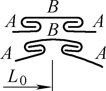 | 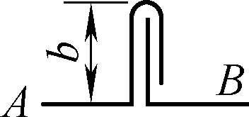 | 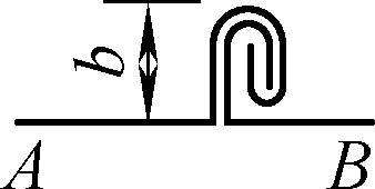 |
Allowance coefficient K | KA=3, KB=2 | KA=4, KB=2 | KA=1, total set B Length 4.5b | KA=2, KB=1 | KA=3, KB=2 |
Explanation | See notes 6, 7 | ||||
Note:
1. Corner seams are widely used for angular connections, such as the upper (lower) base connections of basins, buckets, boxes, and covers, and the connections of various curved surfaces with the base.
2. For general component plates t=0.2~1.5mm, take b=5~8mm.
3. Tapered locks are used for cylindrical surfaces of various pipe shapes, large components can take b=12.7mm.
4. The illustrated position can be rotated 90° for use.
5. Used for non-critical connections (not requiring high strength), such as general areas of roofs, iron doors.
6. Most widely used, can be used for planar, cylindrical, or other curved surface connections of various components, and small plate connections. For circumferential connections of cylindrical parts, use inner flat single lock for smooth inner walls, and outer flat single lock for flush outer surfaces, applicable to both round and square cylinders.
7. When the material thickness t=0.2~0.5mm plate is used for general component biting, take b=3~5mm; when t=0.5~0.75mm, take b=5~8mm; for large area splicing, take b=12~20mm; for large elbow connections, take b=7~12mm.
8. In the table, KA and KB respectively represent the allowance coefficients of parts A and B in the diagram.
9. Among the above biting structures, the compound lock has the highest connection strength and sealing performance, followed by the double lock, the single lock is higher than the half lock, and the sleeve lock and card lock are slightly higher than the double lock.
2. Biting operation methods and precautions
Biting operations are divided into two methods: manual biting and mechanical biting.
(1) Manual biting operation steps
Below provides the steps for manual biting operations.
1) Flat seam
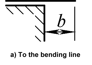

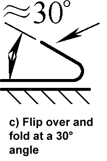
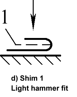
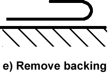
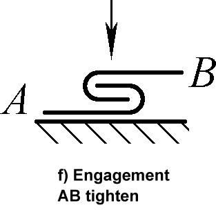
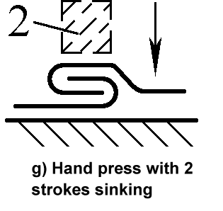
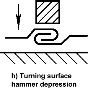
2) Standing seam double
The operation steps for the first bend of part A are the same as a)~d)
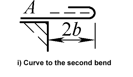
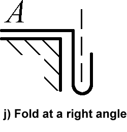
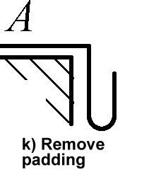
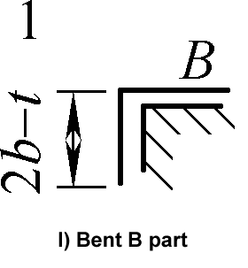
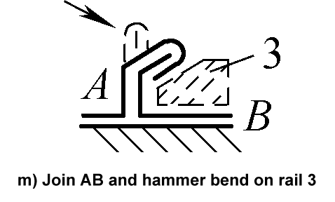
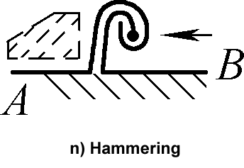
3) Tapered lock
The operation steps for the first bend of part A are the same as b)~d)
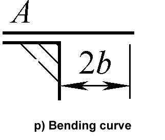
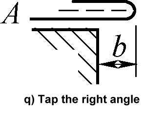
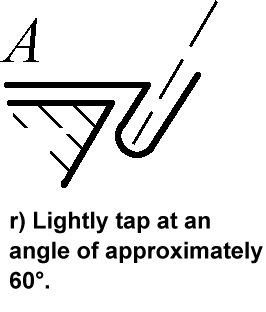
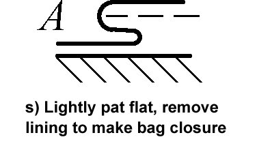
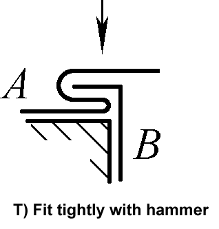
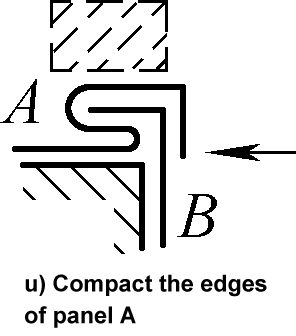
(2) Mechanical biting operation steps
The operational steps of mechanical seaming are basically the same as manual seaming. For batch seaming connections, special equipment can be made for seaming processing. Figure 44 shows the steps for processing cone buckles using a folding machine.
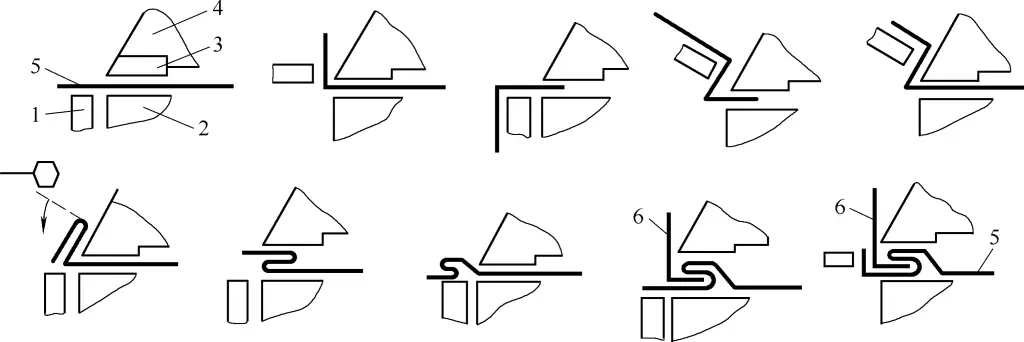
1—Lower inlay strip and edge folding
2—Lower workbench
3—Upper inlay strip
4—Press block
5—Workpiece A
6—Workpiece B
(3) Determination of seaming blanking size
The blanking size L for seaming can be determined by the following formula:
L=L0+Z
In the formula
- L0-Nominal size of the part;
- Z-Seam allowance, determined by Z=Kb, where K is the allowance coefficient (refer to Table 14 for the allowance coefficient K in various seaming forms), b is the seam width, usually taken as b=(8~12)t.
(4) Precautions for seaming operations
The main tools used in manual seaming operations are hammers, bent-nose pliers, tapping boards, angle iron boxes, and gauge irons. During operation, the seaming part blanks must leave enough seaming allowance according to the requirements of the seaming blanking size, otherwise, the finished parts will become waste.
Manual seaming is connected by mutual interlocking, so determining the seaming amount is crucial. The seaming amount for various seamings should be determined with reference to Table 14. In addition, the first and second edge foldings of the interlocking connectors must be matched; otherwise, the seaming will not meet the requirements, which is something to pay special attention to during operation.
The form of seam buckles should not be limited to the structural patterns listed in Table 14. They can be used flexibly and comprehensively according to specific situations. For example, Figure 45a shows the use of a flat seam connection at the cross-section of a cylindrical surface; Figure 45b shows the use of a sleeve buckle connection for a longitudinal corner seam; Figure 45c shows a structure where an S-shaped sliding buckle is used at duct 1, and a sleeve buckle connection is used at 2. When using a sleeve buckle connection, all connection parts must be straight; otherwise, the edges of the entire duct will be uneven. Figure 45d shows the use of two thin sheets to make a sleeve for a wooden board, with one sheet nailed to the wooden board using an S buckle and connected to the other sheet with a sliding buckle.

Figure 46 shows a tenon buckle connection for connecting a cylinder and a flange, i.e., dividing the end of a cylinder or oval tube into an even number of seams, bending every other piece at a right angle as a tenon block (see Figure 46a), and after fitting the flange, hammering the straight tenon piece to wrap around the flange to be connected (see Figure 46b). If sealing is required, soft soldering can be used to fix the seam.

VII. Threaded Connection
A threaded connection is a detachable fixed connection composed of threaded parts. It has the advantages of simple structure, reliable connection, easy assembly and disassembly, and low cost, but the fastening action is slow, and the time for assembly and disassembly is longer. Although the proportion of threaded connections in sheet metal components is not large, it is an indispensable connection method.
1. Forms of Threaded Connection
According to the form of the connecting parts, threaded connections can be divided into screw connections and bolt connections; according to the purpose of the connection, threaded connections can be divided into strong connections and tight connections.
Strong connections only ensure connection strength, while tight connections must ensure both connection strength and the sealing performance of the connection parts. For example, used in pressure gauges and gas or liquid pipeline joints, threaded connections also have a sealing function.
For tight-type threaded connections, sealing pipe threads, tapered internal or external threads, cylindrical internal and external thread connections, or ordinary threads with sealing materials (sealants, sealing tapes, etc.) are often used to achieve sealing.
For threaded connections that bear high-strength loads, high-strength bolt connections are often used (high-strength bolt connections rely on the frictional resistance between the connecting parts to bear the load). High-strength bolt materials are made of alloy steel (35VB, 35CrMo) and high-quality carbon structural steel (45 steel), with coarse thread specifications ranging from M12 to M30.
Table 16 shows the forms of threaded connections.
Table 16 Forms of Threaded Connections
Connection Form | Diagram | Description | |
Bolt Connection | Ordinary |  | The bolt hole diameter is 1~1.5mm larger than the bolt rod diameter, the hole-making requirements are not high, the structure is simple, easy to assemble and disassemble, and it is the most widely used. |
Fit | The bolt rod of a reamed hole bolt fits with the through hole using a transition fit, relying on the shear stress of the bolt rod and the extrusion of the joint surface to balance the external load, with good lateral load-bearing capacity and positioning ability. | ||
High Strength | The bolt hole diameter is larger than the bolt rod diameter, relying on the bolt tightening to bear tension and the joint surface to bear pressure to generate friction to balance the external load. This method is often used in steel structure connections to replace riveting. | ||
Double-Ended Bolt Connection |  | Both ends of the double-ended stud have threads, with one end having a shorter thread that is screwed into the threaded hole of the thick connected part, and the other end passing through the through hole of the thin connected part, connecting the two parts by tightening a nut. Suitable for situations where frequent assembly and disassembly are required, where one of the connected parts is too thick to make a through hole, or where structural limitations prevent the use of bolt connections. | |
Screw Connection |  | Directly pass the screw through the through hole of one connected part and screw it into the threaded hole of another connected part to tighten and connect the two parts. Suitable for situations where frequent disassembly is not advisable, where one of the connected parts is relatively thick and inconvenient to make a through hole, or where structural limitations prevent the use of bolt connections. | |
2. Operation of Threaded Connection
The operation of threaded connections mainly includes thread processing and bolt tightening.
(1) Thread Processing
Depending on the type of thread being connected, the processing method of the thread also varies. Common thread processing methods include turning, extrusion, rolling, broaching, etc.
For sheet metal processing components, ordinary threads are used most frequently, and the most commonly used processing method is drilling and tapping, i.e., using a hand drill or drilling machine to drill the thread bottom hole, then manually tapping the thread or using a drilling machine to tap the thread. The drill diameter d2 for drilling the thread bottom hole before tapping can be determined as follows.
For metric threads, when the pitch t<1mm, d2=d-t; when the pitch t>1mm, d2=d-(1.04~1.06)t. Here, d is the nominal diameter of the thread.
For inch threads, when the nominal diameter of the thread d=3/16~5/8in㊀, the drill diameter for the bottom hole of cast iron and bronze threads is d2=25(d-1/n); for steel and brass threads, the drill diameter is d2=25(d-1/n)+0.1. When the nominal diameter of the thread d=3/4~(1+1/2)in, the drill diameter for the bottom hole of cast iron and bronze threads is d2=25(d-1/n); for steel and brass threads, the drill diameter is d2=25(d-1/n) +0.2. Here, d is the nominal diameter of the thread (in), and n is the number of threads per inch. (Note ㊀1in=25.4mm)
(2) Bolt tightening
Bolts should be tightened at least twice, and an appropriate tightening sequence should be chosen. Tightening bolts in sequence ensures that each bolt in the group is evenly stressed.
The tightening sequence of bolts has two requirements: one is the number of times the bolt itself is tightened, and the other is the tightening sequence between bolts. The tightening sequence of bolts is divided into flange-type structures (see Figure 47a) and plate-type, box-type nodes (see Figure 47b, c).
a) Flange type
b) Plate-type node
c) Box-type node
Note: ①~⑧ indicate the bolt tightening sequence.
1) Flange-type structure bolt tightening sequence
Bolts on pressure vessels are often arranged in a ring shape. In flange connections, tightening bolts in sequence ensures that the bolts are evenly stressed, ensuring stable sealing performance. Figure 48 shows the blind flange bolt tightening sequence during pressure testing.
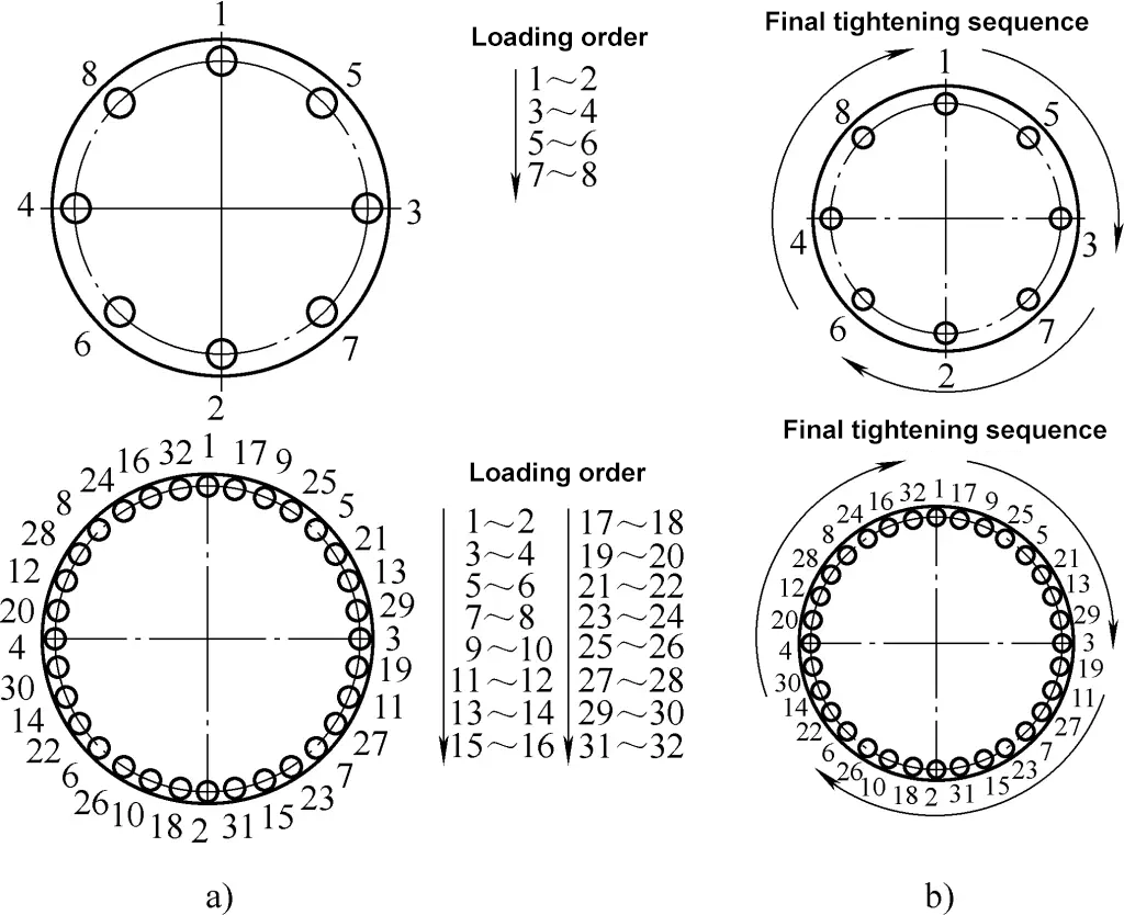
a) Diagonal tightening sequence during load tightening
b) Sequential tightening sequence during final tightening
Pre-tightening mainly involves correctly placing and fixing the sealing ring and flange blind plate on the connecting flange through the bolts. The connection between bolts is only tightened but not fully tightened. Pre-tightening is especially important for the placement of vertical and inclined flange blind plates, as it significantly affects sealing quality. For convex-concave flanges, ensure the sealing gasket is accurately embedded before proceeding to subsequent load tightening.
After inspection, confirm that the sealing gasket is placed correctly and that each bolt is evenly in a just-stressed state before proceeding to load tightening. The bolt tightening sequence should be diagonal, as shown in Figure 48a.
The number of load tightenings is related to the bolt diameter and thread profile. The number of tightenings increases with the bolt diameter, and threads with trapezoidal or sawtooth profiles require more tightenings.
During the final tightening process, the tightening sequence is carried out sequentially from the first point, as shown in Figure 48b. This is distinctly different from the load tightening sequence. The number of final tightenings follows the same pattern as load tightenings.
2) Plate-type, box-type node high-strength bolt tightening sequence
The tightening of high-strength bolts in plate-type and box-type nodes is carried out in an outward expansion or symmetrically from the middle of the node plate joint, as shown in Figure 47b, c.
3) High-strength bolt tightening sequence
The initial and final tightening sequences generally proceed from the middle of the bolt group to the ends or outward. Control elements on pipelines such as steam traps, expansion joints, globe valves, pressure reducing valves, safety valves, throttle valves, check valves, and tapered blind flanges must ensure that the installation direction is consistent with the flow direction of the medium.
VIII. Expansion Joint
Expansion joint is a method of applying pressure to the inner wall of the pipe material, causing plastic deformation of the pipe and elastic deformation of the tube sheet, thereby expanding the end to achieve a tight connection between the pipe material and the tube sheet hole. This method is widely used in the manufacture of boilers and heat exchangers.
1. Joint forms
Several common expansion joint forms and their applicable ranges are shown in Table 17.
Table 17 Several common expansion joint forms and applicable ranges
Expansion joint | Smooth hole expansion joint | Flanged expansion joint | Flared expansion joint | Grooved expansion joint | End face weld ring seam expansion joint | |
Smooth hole expansion joint | Grooved expansion joint | |||||
Diagram | 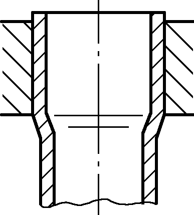 | 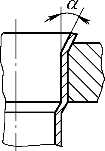 | 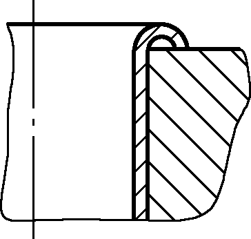 | 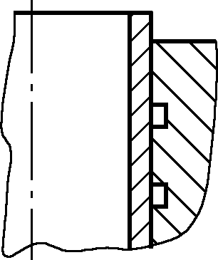 | 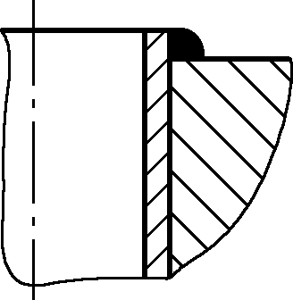 | 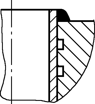 |
Description | Expansion joint length ≤20mm Working conditions: working pressure less than 0.6MPa; working temperature less than 300℃ | α=12°~15° Working conditions: working pressure greater than or equal to 0.1MPa but less than 1.6MPa (low-pressure boiler) | Working conditions: same as flanged expansion joint | Expansion joint length ≤20mm Working conditions: working pressure less than 3.9MPa; working temperature less than 300℃ | Working conditions: working pressure less than 7MPa Temperature less than 350℃ | Working conditions: high temperature and high pressure |
2. Tube expansion methods and tools
In sheet metal processing, the commonly used tube expansion method is mechanical tube expansion. The tools used include spiral tube expanders (suitable for copper tubes or as auxiliary tools), forward tube expanders (suitable for tube diameters ϕ10~ϕ180mm, see Figure 49), and backward tube expanders (suitable for small diameter thick tubes).

1—Flanging roller
2—Three expansion hole rollers (expanders)
3—Expansion rod
4—Expansion shell
3. Key points of tube expansion processing
Generally speaking, tube expansion processing follows the following process: tube annealing (annealing temperature: carbon steel tube 600~650℃, alloy steel tube 650~700℃) → check and carefully clean the tube and plate hole → initial expansion positioning → re-expansion → flanging → tube end weld seam → inspect expansion tightness.
Due to the many factors affecting the quality of tube expansion, in actual operation, the processing quality of each tube expansion process should be strictly controlled, mainly including the following aspects.
(1) Expansion tightness
The expansion tightness directly affects the quality of tube expansion processing, so the expansion tightness should be controlled within a certain range. Insufficient expansion and over-expansion will affect the strength and sealing of the joint. In actual operation, the diameter of the expansion hole and the outer diameter of the tube material should be strictly controlled.
Whether the expansion tightness is appropriate is mainly determined by the feeling of arm strength, the sound of the tube expander, and the degree of deformation of the tube material. Additionally, the peeling phenomenon of the oxide layer cracks around the plate hole can also be used to judge whether the expansion tightness meets the requirements.
(2) Determination of the gap between the tube plate hole and the tube material
A reasonable gap between the tube plate hole and the tube material is an important factor to ensure the expansion rate and quality. Too large a gap will reduce the expansion degree, affecting the connection strength; too small a gap will make it difficult to insert the tube during assembly.
Choosing a reasonable gap is an essential task before tube material expansion assembly, which can be done through actual measurement based on specific size conditions. Table 18 shows the maximum gap between the tube plate hole and the heat exchange tube.
Table 18 Maximum gap between tube plate hole and heat exchange tube
| Working pressure/MPa | Maximum diameter of heat exchange tube/mm | |||||||
| 32 | 38 | 51 | 60 | 76 | 83 | 102 | 108 | |
| Maximum gap between tube plate hole and heat exchange tube/mm | ||||||||
| ≤3.0 | 1.2 | 1.4 | 1.5 | 1.5 | 2.0 | 2.2 | 2.6 | 3.0 |
| >3.0 | 1.0 | 1.0 | 1.2 | 1.2 | 1.5 | 1.8 | 2.0 | 2.0 |
(3) Treatment of tube ends
The treatment of tube ends includes softening heat treatment and rust removal. The purpose of softening heat treatment of tube ends is to achieve a good expansion effect by stress-relieving annealing of the ends of the heat exchange tubes to achieve softening. The method of stress-relieving annealing is to heat the tube ends above the recrystallization temperature and cool slowly.
The sulfur content of the heating fuel for annealing should be strictly controlled to avoid sulfur infiltration during heating. The oxide layer on the surface of the heat-treated tube ends should be removed to ensure the quality of the expansion.
The annealing temperature for carbon steel tubes is 600~650℃, for alloy steel tubes is 650~700℃. The annealing length should be the thickness of the tube plate t plus 100mm, with a holding time of 10~15min, and slow cooling in lime or furnace ash.
Tube end heating can use coke and other heat sources, or lead bath heating. Lead bath heating has the characteristics of uniform heating, preventing sulfur infiltration, and convenient and strict temperature control. To prevent lead oxidation and the harm of lead vapor, a 10mm thick protective layer of furnace ash can be covered on the surface of the lead liquid.
(4) Lubrication during tube expansion
Lubricating the tube expander during tube expansion helps the processing and protects the tube expander. However, care must be taken not to allow lubricating oil to enter the expansion area between the tube plate and the tube end to avoid reducing the sealing performance of the expansion and to prevent pores during expansion. If the expansion area is accidentally contaminated with lubricating oil, it can be cleaned with acetone.
(5) Tube expansion sequence
Choosing a reasonable tube expansion sequence is beneficial to improving the quality of the expansion. The general principle of the expansion sequence is: first, intermittent expansion to fix the distance of the tube plate, then continuous expansion of all the tube materials.
For tube boxes combined with tube plates, an improper expansion sequence can cause significant deformation of the tube plate (bending or becoming dish-shaped), and even cause the sealing surface of the tube plate to fail.
The reason for deformation is that some tube materials in the initial expansion have fixed the distance of the tube plate. If other tube materials are expanded in sequence, the axial elongation of the tube materials will be hindered by the tube plate, causing each tube material to push the tube plate and deform it. The correct tube expansion sequence for tube boxes combined with tube plates is shown in Figure 50.
The main operation points are: first, expand the tube materials marked 1 to 6 in the first circle in sequence, ensuring the distance between the two tube plates and that the tube plate and tube materials are perpendicular to each other; secondly, to increase the rigidity of the tube plate, some tube materials in the second and third circles that are spaced from the previously expanded tube materials can be expanded, but attention should be paid to expanding them symmetrically like the tube materials 1 to 6.
Finally, to ensure uniform stress on each joint, first expand the odd-numbered rows (such as the 1st, 3rd, 5th rows shown in Figure 50) of tube materials, and then expand the even-numbered rows.
