I. Basic Process Knowledge
1. Concept and Application of Sawing
The operation of cutting or slotting materials or workpieces with a hand saw is called sawing. Its applications are shown in Figure 1.
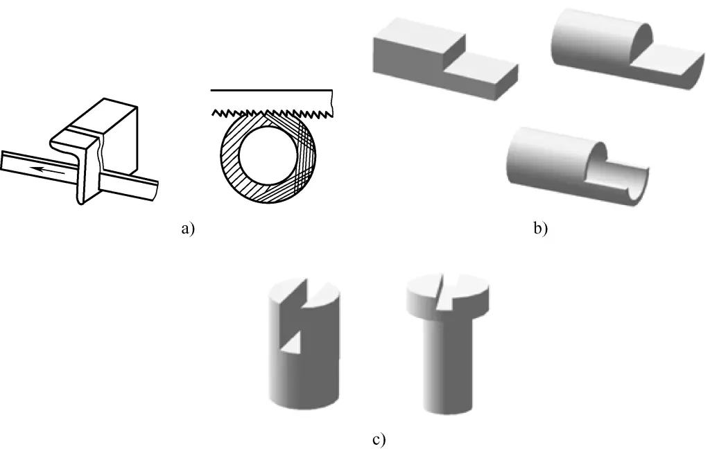
a) Cutting materials
b) Removing materials
c) Slotting
2. Sawing Tools
(1) Hand Saw
A hand saw consists of two parts: the saw frame and the saw blade. The saw frame is used to clamp and tension the saw blade, and there are two types: fixed frame and adjustable frame. Figure 2 shows a fixed frame saw, and Figure 3 shows an adjustable frame saw.

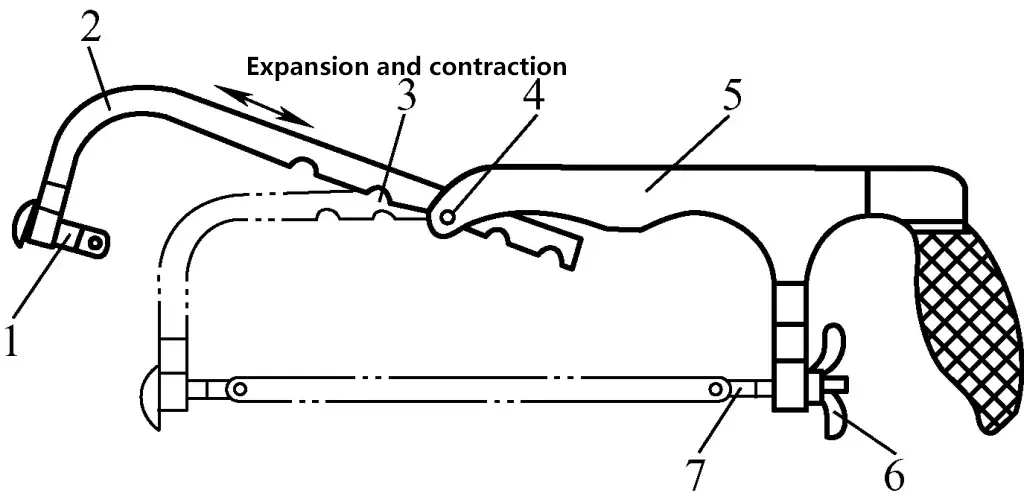
1—Fixed clamp head (square tenon)
2—Adjustable saw frame
3—Semi-circular slot
4—Limiting slot
5—Fixed saw frame
6—Wing nut
7—Movable clamp head (square tenon)
Since the front section of the adjustable saw frame can freely extend and retract within the rear section, it can accommodate saw blades of different lengths, making it widely applicable. The saw blade is placed on the round pins of the fixed clamp head and movable clamp head, and by tightening the wing nut on the movable clamp head, the tension of the saw blade can be adjusted.
(2) Saw Blade
The size of a saw blade is indicated by the distance between the mounting holes at both ends. The commonly used size is 300mm long, 12mm wide, and 0.8mm thick.
1) Saw Tooth Angles
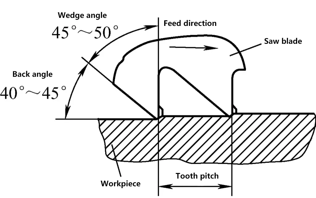
As shown in Figure 4, the back angle of the saw tooth is 40° to 45°, the wedge angle is 45° to 50°, and the front angle is about 0°.
2) Tooth Pitch
The distance between two adjacent saw teeth is called the tooth pitch. The larger the tooth pitch, the larger the chip space. Based on the size of the tooth pitch, saw blades can be classified into three types: coarse teeth, medium teeth, and fine teeth, as shown in Table 1.
Table 1 Saw Tooth Specifications and Applications
| Tooth Coarseness | Number of teeth per 25mm | Tooth Pitch/mm | Application |
| Coarse | 14-18 | 1.8-1.5 | Sawing soft materials such as copper, aluminum, or thick workpieces |
| Medium | 19-23 | 1.3-1.1 | Sawing medium-hard materials such as ordinary steel, cast iron, etc. |
| Fine | 24-32 | 1.0-0.8 | Sawing hard steel and thin-walled workpieces, etc. |
3) Saw kerf
The teeth on the saw blade are set alternately to the left and right to form the saw kerf. There are two types of shapes, as shown in Figure 5a, the wavy saw kerf; and in Figure 5b, the alternating saw kerf. During sawing, the saw kerf forms the saw cut. Since the width of the saw kerf S is greater than the thickness of the saw back b, the width of the saw cut is always greater than the thickness of the saw back, making it less likely for the saw blade to get stuck in the cut (reducing the occurrence of saw pinching).
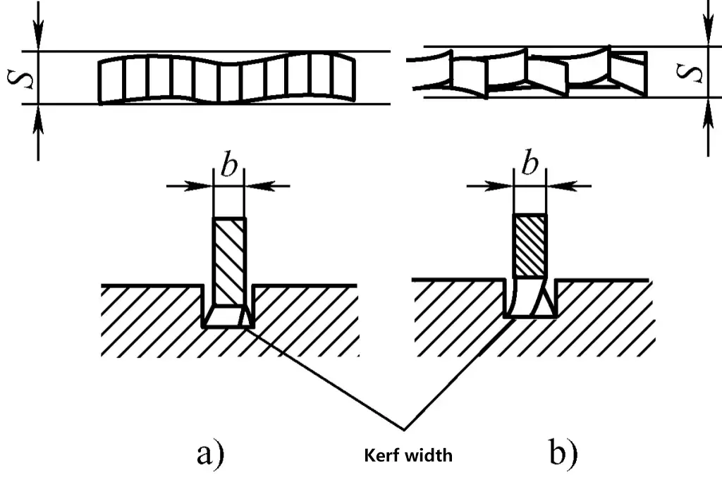
a) Wavy tooth pattern
b) Alternating tooth pattern
Practice has shown that as the saw teeth wear down, the width of the saw kerf decreases. When its width is no longer greater than the thickness of the saw back, the width of the resulting saw cut is also no longer greater than the thickness of the saw back. This leads to severe friction between the saw blade and the cut, making sawing difficult and causing saw pinching, and may even break the saw blade.
4) Selection of saw blades
Choose saw blades of different coarseness according to the hardness and thickness of the workpiece material. When sawing soft materials or thick workpieces, use coarse-toothed saw blades with larger chip spaces. When sawing hard materials and thin workpieces, use medium-toothed or even fine-toothed saw blades to prevent blade sticking and reduce tooth chipping and dulling.
Generally, coarse-toothed saw blades are suitable for sawing soft metals such as copper and aluminum, as well as thick workpieces; fine-toothed saw blades are suitable for sawing hard steel, sheet metal, and thin-walled pipes; while medium-toothed saw blades are mostly used for processing ordinary steel, cast iron, and medium-thickness workpieces, as shown in Figure 6.

a) Coarse teeth for thick workpieces
b) Fine teeth for thin workpieces
II. Basic Operating Skills
1. Installation of the saw blade
1) Choose a suitable saw blade according to the workpiece material and thickness.
2) The adjustable saw frame of the adjustable hacksaw must be placed in the inner slot of the fixed saw frame, so that the top surface of the adjustable saw frame is in line with the fixed saw frame.
3) Installation direction. Figure 7a shows the correct installation direction of the saw blade, while Figure 7b shows the incorrect installation direction. If the saw blade is installed backwards, it not only fails to cut but also causes rapid wear of the saw teeth.
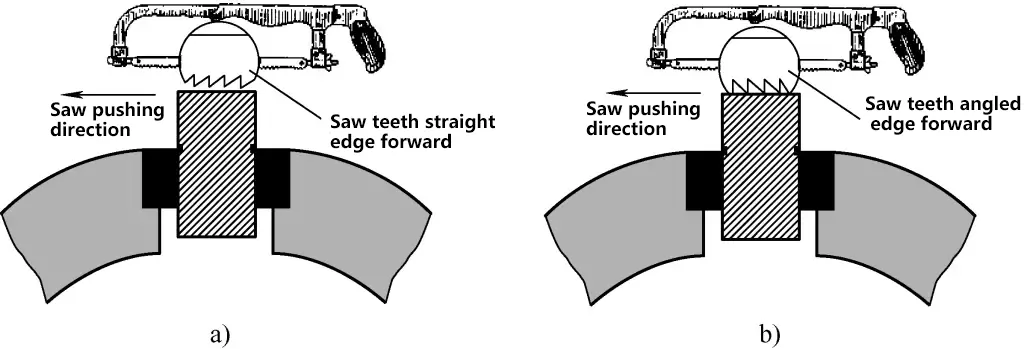
a) Correct installation direction of the saw blade
b) Incorrect installation direction of the saw blade
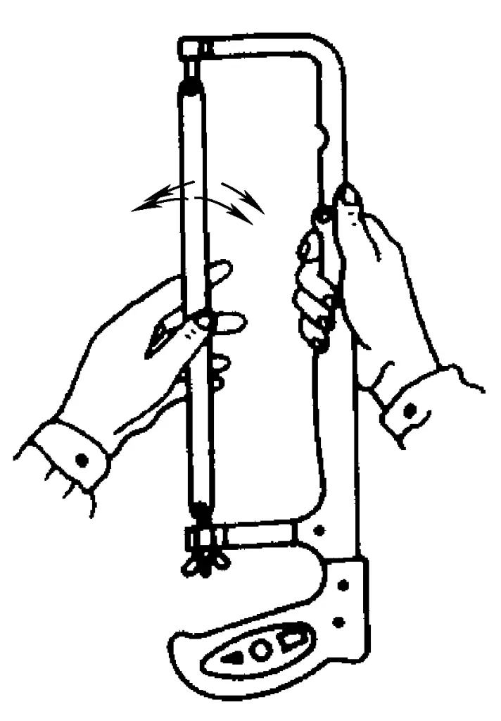
4) Tension of the saw blade installation. If the saw blade is installed too tightly, it loses its elasticity and is prone to breaking; if installed too loosely, the saw blade can twist under pressure, causing the saw cut to be skewed and also prone to brittle fracture. Based on experience, after tightening the saw blade, use two fingers to push the saw blade left and right; it should have a slight turning movement but no wobbling, as shown in Figure 8.
5) After the saw blade is installed, its plane should align with the center plane of the saw frame, without any twisting.
2. Workpiece clamping during sawing
Figure 9 shows the clamping position of the workpiece during sawing, with the following key points:

- The workpiece should be clamped as far left as possible in the bench vise, with the cutting line parallel to the vise jaws, about 5-10mm from the iron jaws.
- The workpiece should protrude as little as possible in the vertical direction, otherwise it will vibrate during sawing and may even break the saw blade.
- The workpiece must be clamped securely to prevent movement during sawing, which could break the saw blade.
- When sawing pipes and soft metals, especially when clamping machined workpiece surfaces, use soft pads to prevent damage to the workpiece.
3. Key points of sawing operation
(1) Grip of the saw frame
The correct way to grip the saw frame is shown in Figure 10. The right hand firmly grasps the handle, while the left hand lightly rests on the curved part of the saw frame, with the thumb pressing on the back of the saw frame and the other four fingers gripping the front end. The movement of the saw frame and the pressure and pushing force during sawing are mainly controlled by the right hand, with the left hand assisting in supporting the hand saw.
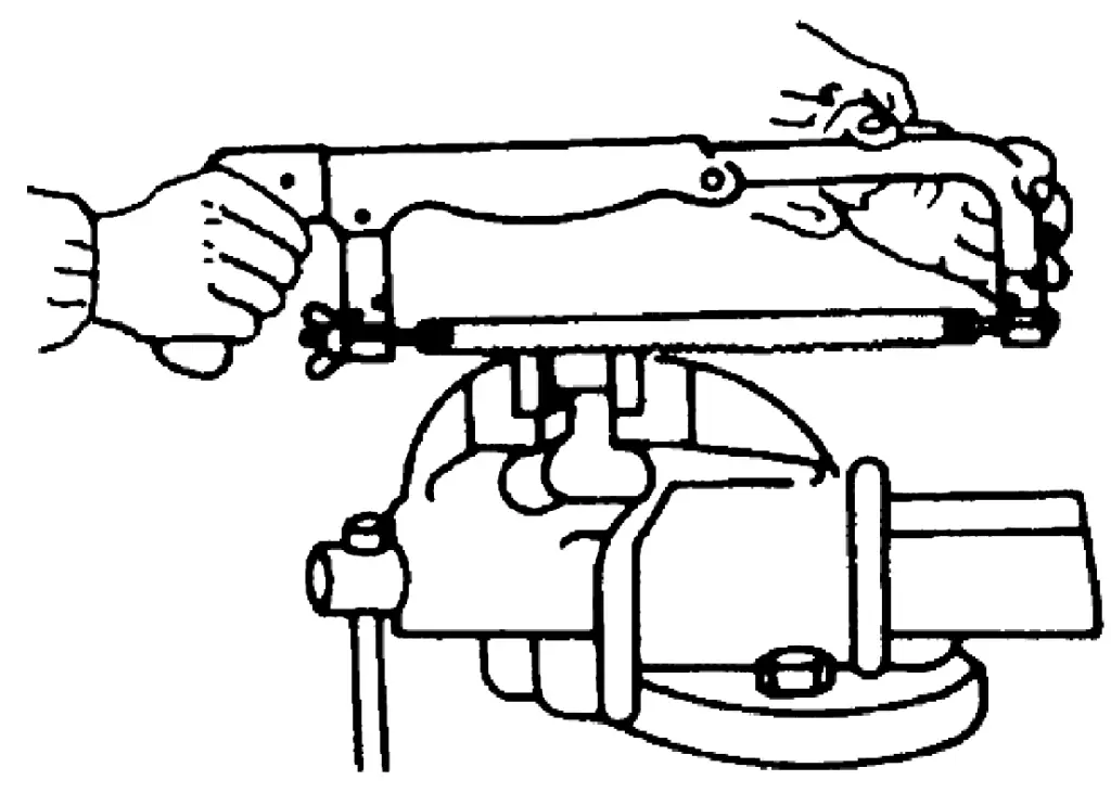
There are two common incorrect grips: ① placing the left pinky finger under the saw tenon; ② fully gripping the front end of the saw frame with the left hand.
(2) Sawing standing posture
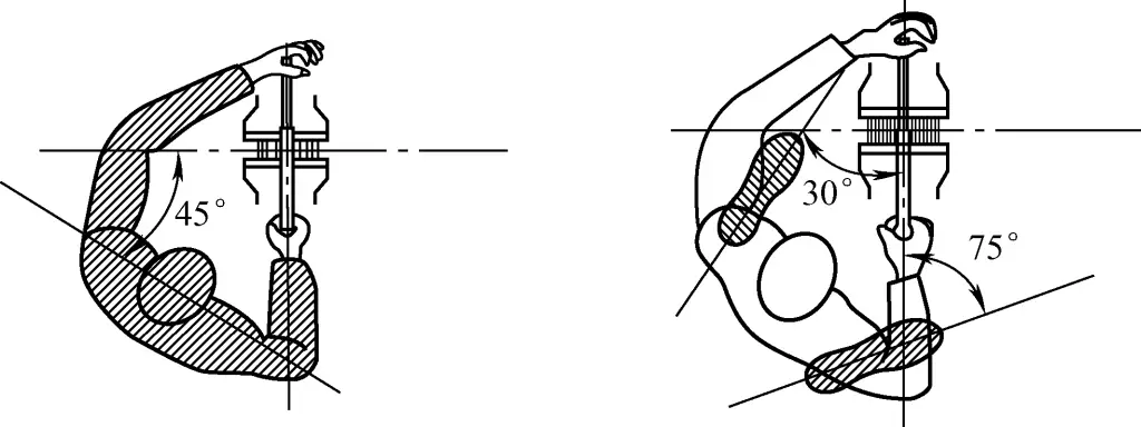
As shown in Figure 11, stand firmly with both feet facing the bench vise, positioned to the left of the centerline of the bench vise, at a distance approximately equal to the full length of the saw blade; then step forward with the left foot, with the distance between the right toe and the left heel approximately equal to the length of the saw frame. The left foot should form a 30° angle with the centerline of the bench vise, and the right foot should form a 75° angle.
(3) Starting the saw
Starting the saw is the first step in the sawing process, and the quality of the start directly affects the quality of the sawing.
To start the saw smoothly, use the left thumb to hold the saw blade in place where you need to start (be sure to follow the marked cutting line and clearly identify which piece is the workpiece to be retained for processing to avoid scrapping the workpiece, as shown in Figure 12).
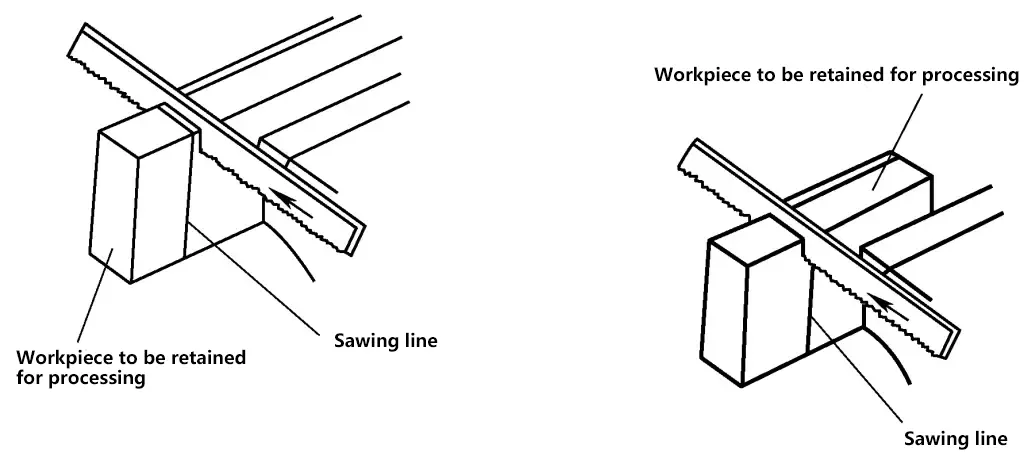
When first starting to saw, apply light pressure and use short reciprocating strokes. Once the groove is 2-3mm deep, release the hand holding the saw blade and move the saw frame to a horizontal position for normal sawing.
There are two common methods for starting the saw: far start and near start.
1) Far start
Far start is the commonly used method for starting the saw. As shown in Figure 13a, far start begins sawing from the end of the workpiece farthest from you. Since the saw teeth gradually cut into the workpiece, it prevents the teeth from getting caught on the workpiece edge and chipping.

a) Far start
b) Near start
2) Near start
As shown in Figure 13b, near start begins sawing from the end of the workpiece closest to you. The advantage is that you can clearly see the cutting line, but if not done properly, the saw teeth can easily get caught on the workpiece edge and break.
Regardless of which starting method is used, the starting angle should be less than 15°. If the starting angle is too large, the saw teeth will hook onto the workpiece edge and chip; if the starting angle is too small or flat, the saw teeth will not easily cut into the material or may slip and fray the workpiece surface.
(4) Sawing operation process
As shown in Figure 14, when sawing forward, lean the body slightly forward and naturally press towards the saw frame. When the forward stroke reaches about two-thirds of the saw blade length, allow the body to return to position using the reactive force of sawing.
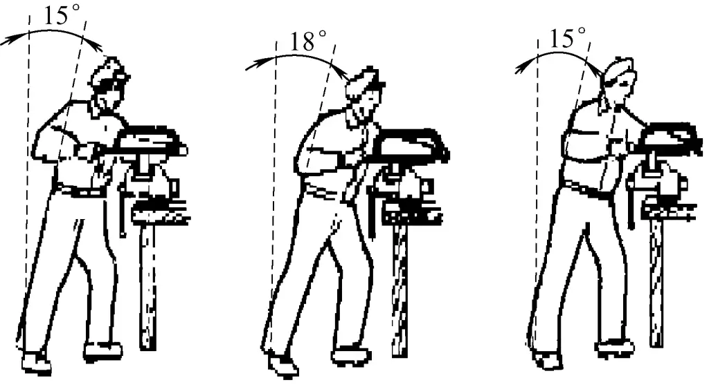
On the return stroke, lift the saw frame slightly with the left hand, allowing the saw blade to glide lightly over the workpiece. Once the body returns to the initial position, prepare for the second reciprocation. Throughout the sawing process, maintain a straight saw cut, correcting any skewing immediately.
(5) Two common sawing forms
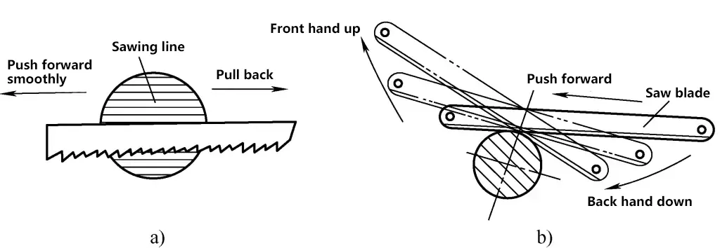
1) Straight reciprocating sawing, as shown in Figure 15a, involves controlling the saw frame to move in a straight reciprocating motion with both hands, whether pushing forward or pulling back. This sawing form is called straight reciprocating sawing. It minimizes the left and right swinging of the saw frame, making it easier to achieve a straighter saw cut and a flatter bottom when cutting grooves.
a) Straight reciprocating sawing
b) Small amplitude swinging sawing
2) Small amplitude swinging, as shown in Figure 15b, involves lifting the front forearm and lowering the back forearm when pushing the saw forward, and lifting the back forearm and lowering the front forearm when pulling back, creating a small amplitude swinging motion of the saw frame.
Compared to straight reciprocating sawing, this method’s main advantage is reduced fatigue during long periods of sawing. The disadvantage is that the up and down swinging of the front and back forearms can cause some left and right swaying of the saw frame, affecting the straightness of the sawn surface. Additionally, when cutting grooves, the bottom of the groove will be arc-shaped.
(6) Control of sawing force
During manual sawing, the operator controls the force applied by the hand saw to the workpiece material, including the sawing push force and the sawing pressure force. The principle of force application in sawing is to maintain an appropriate sawing pressure while achieving smooth, steady pushing without sticking.
1) As shown in Figure 4, when pushing the saw forward, the saw teeth are in a cutting state; when pulling the saw back (return stroke), the saw teeth do not cut. Therefore, the operator should apply sawing pressure when pushing forward and slightly lift the saw during the return stroke without applying pressure, otherwise it will accelerate the wear of the saw blade.
2) The operator should choose a reasonable sawing pressure based on the hardness of the material being processed. When sawing soft materials (such as copper, aluminum, low carbon steel, etc.), apply less pressure to prevent cutting too deep and causing binding; when sawing hard materials (such as high carbon steel, cast iron, etc.), apply greater pressure as they are not easy to cut into, to prevent slipping.
3) During sawing, to ensure stability and safety of the operation, as well as to reduce wear on the saw teeth, the sawing pressure should be adjusted appropriately based on the actual sawing conditions.
① If sawing becomes difficult during the process, analyze the cause promptly. If the saw teeth tips are worn, reduce pressure or change the saw blade; if there are hard spots in the workpiece material, reduce pressure or switch to a fine-toothed saw blade.
② Reduce pressure when the workpiece is about to be cut through.
(7) Control of sawing direction
Sawing along the cutting line to achieve a straight saw cut is a basic requirement for sawing quality. For this, it is necessary to control the sawing direction well during the operation.
1) During sawing, frequently check if the saw cut is deviating from the cutting line, and correct it promptly if there is a tendency to deviate.
2) As mentioned earlier, when installing the workpiece, the cutting line is parallel to the vise jaws, so during sawing, the edge of the vise jaws can be used as a reference line. That is, during the sawing process, try to keep the direction of sawing progress always parallel to the edge of the vise jaws.
3) Try to keep the saw frame from swaying left and right during the sawing process.
(8) Sawing speed and stroke
The appropriate sawing speed is 20-40 strokes per minute. Sawing can be faster for soft materials and should be slower for hard materials. If the speed is too fast, the saw blade will wear out quickly; if too slow, efficiency will be low. To prevent the middle part of the saw blade from dulling too quickly, the sawing stroke should not be less than two-thirds of the blade length, but the front and back saw tenons should not touch the edges of the workpiece.
(9) Correction of skewed saw cuts
During the sawing process, skewed cuts often occur due to the following reasons:
- When installing the workpiece, the direction of the cutting line is not consistent with the vertical direction.
- The saw blade is installed too loosely or is twisted relative to the saw frame plane.
- Using a saw blade with uneven wear on both sides of the teeth.
- Excessive sawing pressure causes the saw blade to sway left and right.
- The saw frame is not held straight or force is applied unevenly, causing the back of the saw blade to deviate from the cut.
If skewing is detected during the sawing process, it should be corrected promptly: As shown in Figure 16, tilt the upper part of the saw frame in the same direction as the skew, apply light pressure downward while sawing, using the fact that the saw kerf is wider than the saw back thickness to correct the cut. Once the cut returns to the correct position, promptly straighten the saw frame and continue sawing using the normal method.

4. Sawing of typical parts
(1) Sawing of flat steel and angle steel
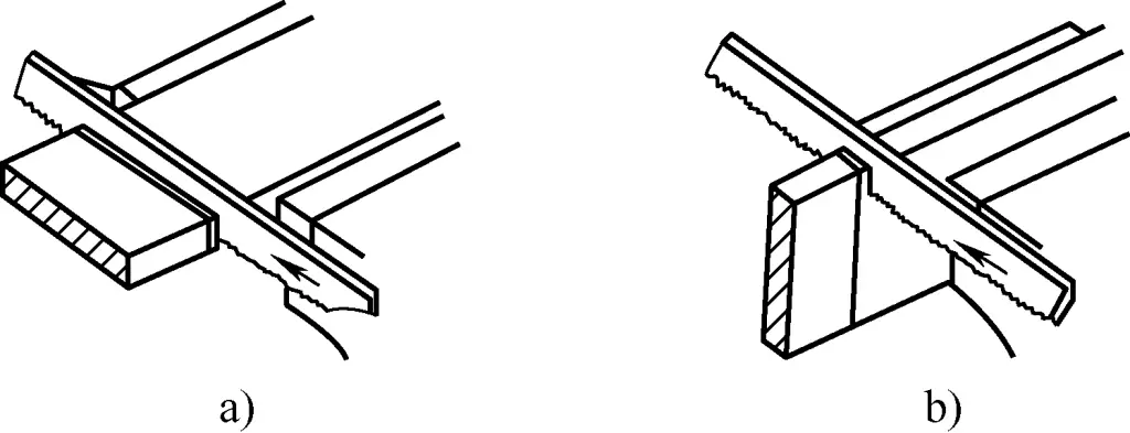
Experience has shown that to ensure the saw teeth are not caught by the edges of the workpiece during sawing and to avoid breaking the saw blade, usually 3-4 teeth should be in contact with the surface being sawn. Therefore, when sawing flat steel or angle iron, sawing should be done from the wide face downwards, as shown in Figure 17. Sawing from the wide face downwards not only improves efficiency but also better prevents chipping of
a) Correct
b) Incorrect
Conversely, if sawing from the narrow side downwards, it is not only uneconomical, but also only a few saw teeth contact the workpiece, causing the teeth to get stuck. The thinner the workpiece, the easier it is for the saw teeth to be caught by the edges of the workpiece and break.
(2) Sawing of channel steel
1) Clamping of channel steel before sawing
Channel steel should be correctly clamped before sawing to prevent deformation during the sawing process that could affect its use. Figure 18 shows the clamping method for channel steel on a bench vise before sawing.

a) Correct clamping method
b) Incorrect clamping method
2) Sawing method for channel steel
As shown in Figure 19, when sawing channel steel, it is generally done in three passes from the wide side downwards. It cannot be sawed down on one side; instead, try to start sawing on the long kerf as much as possible. Therefore, the workpiece must be repositioned multiple times. First, saw one side of the channel steel on the wide surface (see Figure 19a); then flip the channel steel and clamp it to saw the middle part of the wide surface (see Figure 4-19b); finally, turn the channel steel sideways and clamp it to saw the other side of the wide surface (see Figure 19c).

a) Flip one
b) Flip two
c) Flip three
d) Normal sawing path
If the channel steel is clamped only once and sawed open as shown in Figure 19d, firstly, the efficiency is low; secondly, when sawing the high and narrow middle part, the saw teeth are prone to breaking, and the kerf will not be even, so this method is not recommended.
(3) Sawing deep grooves
As shown in Figure 20, when sawing deep grooves, first saw vertically. When the height of the kerf reaches the height of the saw frame, the frame will collide with the workpiece. At this point, remove the saw blade, rotate it 90°, and reinstall it, turning the saw frame to the side of the workpiece, then continue sawing along the original path.

(4) Sawing of tubular materials
1) Clamping of tubular materials before sawing
Tubular materials should be correctly clamped before sawing to prevent deformation of the inner diameter during the sawing process that could affect its use. Figure 21 shows the clamping method for tubular materials on a bench vise before sawing.
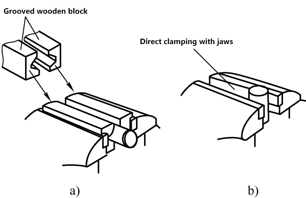
a) Correct clamping method
b) Incorrect clamping method
2) Sawing process for tubular materials
As shown in Figure 22, when sawing tubular materials, it cannot be sawed through from one direction. This is because after the saw penetrates the inner wall of the tube, the saw teeth will cut on the thin wall, and due to concentrated force, they can easily be caught by the tube wall and break.
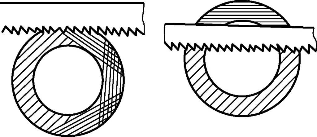
The correct method is: when the saw reaches the inner wall of the tube, stop sawing, rotate the tube slightly in the direction of the saw push, and continue sawing along the original kerf. Keep rotating and sawing until it is cut through. It should also be noted that for thin-walled round tubes, they should be clamped and sawed using V-shaped wooden blocks before sawing.
(5) Sawing of thin plates
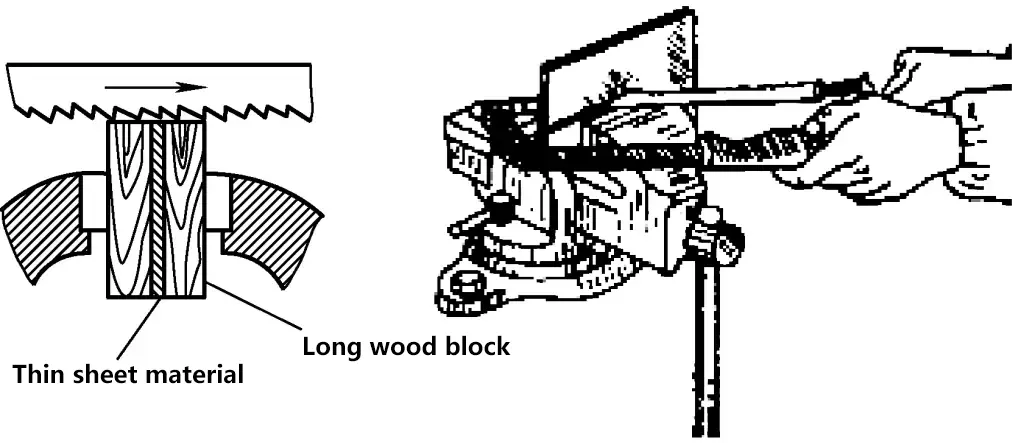
As shown in Figure 23, clamp the thin plate material between two wooden blocks, and then clamp them together in the bench vise for sawing. This increases the rigidity of the thin plate material during sawing and prevents the saw teeth from breaking.
5. Safety precautions for sawing
- The saw blade tension should be appropriate, neither too loose nor too tight.
- Do not apply too much pressure on the hand saw during sawing, otherwise, it may cause the saw blade to break.
- If saw teeth chipping is noticed during the sawing process, address it promptly to prevent further tooth damage.
- When the workpiece is about to be sawed through, apply less pressure and slow down the speed. Use your left hand to support the part being sawed off, and control the saw frame with your right hand to slowly saw off the part to be removed. This prevents injury to the arms from excessive sawing pressure and also prevents the removed part from falling and injuring the feet.

