Section One: Manual Straightening
I. Causes of steel deformation
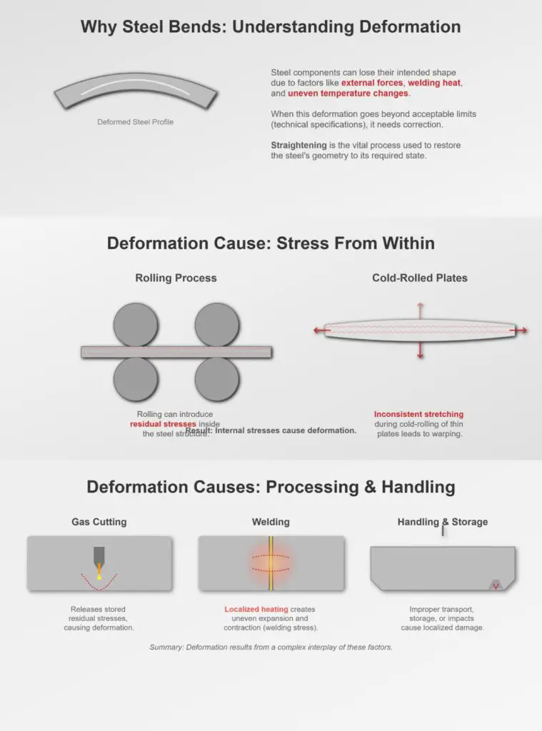
Various sheets and profiles often deform to some extent due to external forces, welding, and uneven heating. If the deformation exceeds the technical specifications, it must be corrected. Straightening is the process of restoring the deformed geometry to within the specified technical range.
The causes of deformation are as follows:
1. Deformation caused by residual stress in steel
During the rolling process, steel may develop residual stresses that cause deformation. Inconsistencies in stretching of cold-rolled thin plates can also lead to deformation.
2. Deformation caused during the processing of steel
Metal undergoes deformation when the residual stresses formed during rolling are released through gas cutting; deformation occurs during welding of steel due to localized heating, and this uneven heating generates welding stress; additionally, improper transportation, storage, or handling can also cause localized deformation. In summary, the causes of deformation in steel are multifaceted and complex.
II. Methods for measuring the degree of deformation in steel
The deformation of steel must not exceed the tolerances, otherwise it will affect the part numbering, cutting, and other processing steps, reducing machining accuracy, and even affecting the correct assembly of the entire structure. Therefore, it is necessary to correct it to eliminate or limit its deformation within the specified range.
The tolerances for steel before use are shown in Table 6-1.
Table 6-1 Tolerances for steel before use
| Geometric accuracy | Simplified Diagram | Tolerance Value |
| Local Deflection of Steel Plates and Flat Steel |  | When δ≥14mm, f≤1mm; when δ<14mm, f≤1.5mm |
| Straightness of Angle Steel, Channel Steel, I-beam, and Pipes |  | f≤L/1000 ≤5mm |
| Verticality of Both Sides of Angle Steel | 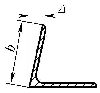 | Δ≤b/100 |
| Inclination of Flanges of I-beam and Channel Steel | 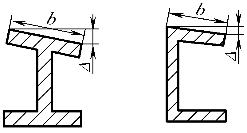 | Δ≤b/80 |
III. Basic Principles and Methods of Manual Correction
Manual correction is a basic skill that must be mastered in actual production. When there is no specialized correction equipment, manual correction is widely used for small-sized plates, profiles, cut parts, and local deformations of welded structures.
Common manual correction involves using various tools such as large hammers, hammers, and metal sheets, employing methods like hammering, wrenching, pulling, and pushing on specific parts of the workpiece to extend and expand the tighter metal, ultimately making the fiber lengths of each layer consistent to achieve the purpose of correction.
1. Correction of Thin Plate Deformation
(1) Correction of bulging deformation in thin plates
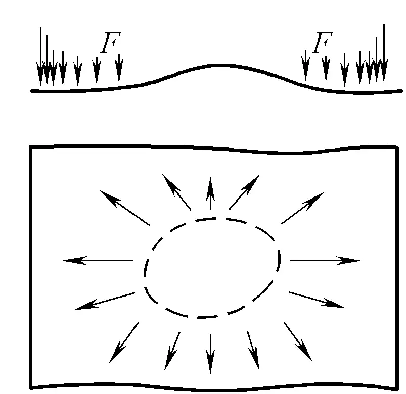
The local bulging of thin plates is caused by the material being loose in the middle and tight around the edges. During correction, start hammering from the edge of the bulge radiating outward, increasing the force and density of the hammering as you move outward, to stretch the fiber layers from the inside out to varying degrees, gradually eliminating the bulging deformation during the hammering process.
If there are several adjacent bulges in the middle of the thin plate, gently hammer at the junctions of each bulge to merge them into one bulge, then hammer around it as described above to flatten it. As shown in Figure 6-1.
(2) Correction of wavy edges in thin plates
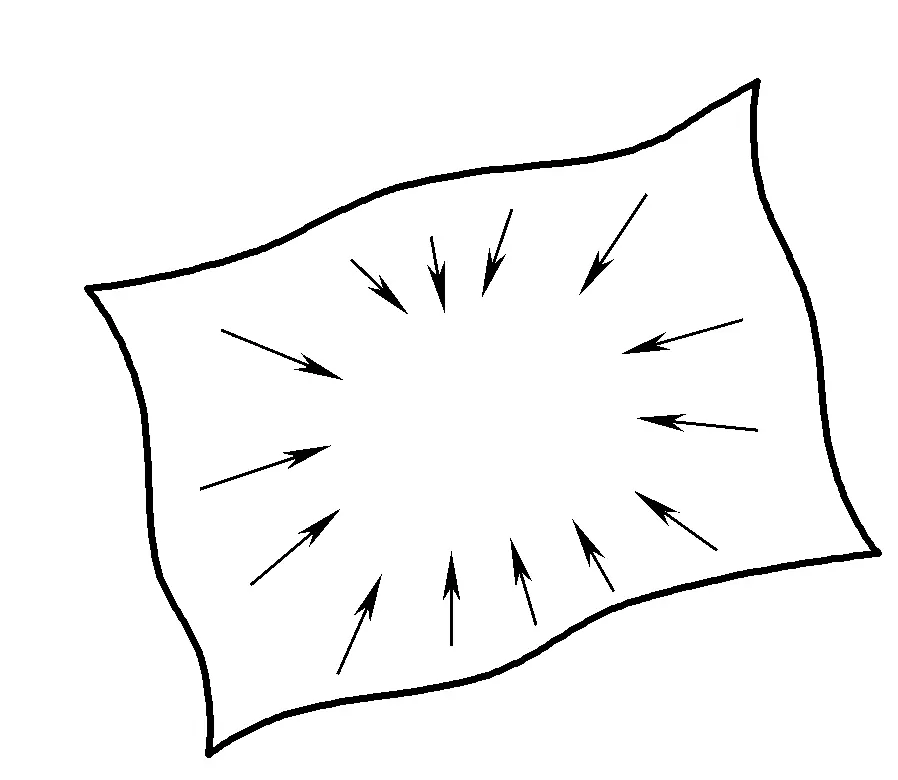
If the edges of the thin plate are wavy, it indicates that the material is loose around the edges and tight in the middle. During correction, hammer from the outside towards the inside, gradually increasing the force and density, to cause greater stretching of the fiber layers in the middle of the plate, achieving the elimination of the wavy deformation around the edges. As shown in Figure 6-2.
2. Correction of deformation in thick plates
The main deformation in thick plates is bending deformation. The following two methods are usually used for correction:
1) Direct hammering at the bulge.
The hammering force must be greater than the yield point of the plate, causing the protrusion to undergo forced compression and plastic deformation to flatten it.
2) Hammer the concave part of the protrusion.
Hammering the concave area can use a smaller force, causing the material to only expand in the concave area, forcing the concave area to be relatively compressed, thereby achieving the purpose of flattening.
3. Manual straightening of profiles and pipes
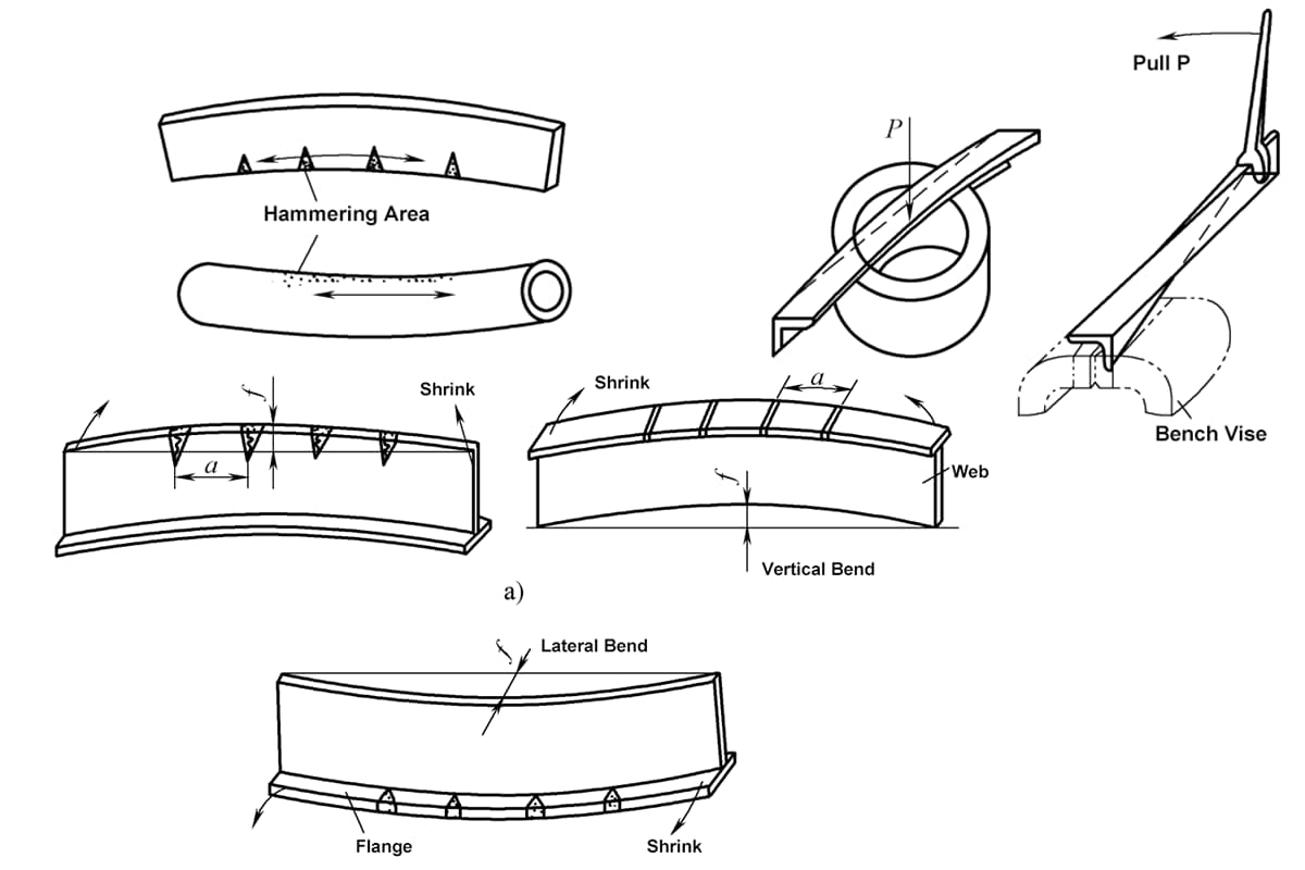
The bending deformation of flat steel, angle steel, round steel, and round pipes can also be corrected by hammer stretching, with the hammering point on the concave side of the workpiece (the arrow in the diagram indicates the direction of hammering and the direction of material extension). As shown in Figure 6-3.
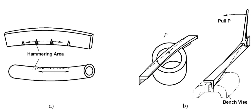
a) Hammer stretching
b) Bending, twisting
In addition, the bending and twisting deformation of profiled steel can also be corrected on platforms, round blocks, and bench vises using tools such as hammers and wrenches, relying on the bending moment formed by the correcting external force to achieve the purpose of correction.
Section Two: Flame Straightening
I. Principle of Flame Straightening
Flame straightening uses the plastic deformation caused by localized heating of metal to offset the original deformation and achieve the purpose of straightening. During flame straightening, the metal at the longer fiber sections of the deformed steel or components should be heated in a controlled manner with focused flame, reaching a certain temperature to obtain irreversible compressive plastic deformation. After cooling, tensile stress is generated in the surrounding material, correcting the deformation.
Metal has the characteristics of thermal expansion and contraction, and can produce both elastic and plastic deformation under external forces. When locally heated, the heated part of the metal expands, but since the surrounding metal is relatively cooler, the expansion is hindered, causing the heated metal to be compressed. When the heating temperature reaches 600~700°C, the stress exceeds the yield limit, resulting in plastic deformation; at this point, the thickness of the material slightly increases, while the length is shorter than if it could expand freely.
For general low carbon steel, when the temperature reaches 600~650°C, the yield limit is close to zero, and the deformation of the metal material is mainly plastic deformation. Now, let’s explain using the example of asymmetric heating on one side of a long strip.
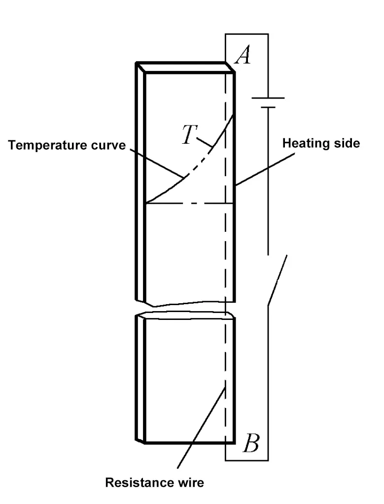
If resistance wire is used as a heat source to rapidly heat one side AB of a narrow strip, due to the fast heating speed, an asymmetrically distributed non-uniform heat field is generated in the strip as shown in Figure 6-4 (where T is the temperature distribution curve). Cutting narrow strips from the entire steel plate with a gas cutter, or welding along one side of the strip, is similar to this situation.
For ease of understanding, assume that the strip is composed of several small strips that are not connected but closely attached to each other, each small strip can expand freely at its own different temperature, resulting in step-like deformations at the ends of each narrow strip corresponding to the temperature curve, as shown in Figure 6-5a.
In reality, since the strip is a whole, the materials in different parts restrain each other, and the strip will exhibit bending deformation along the length direction as shown in Figure 6-5b, bulging towards the heated side. According to the conditions of stress balance, the internal stress distribution of the strip during heating is as shown in Figure 6-5c (metal on both sides is compressed, metal in the middle is stretched).
Since the temperature on the heated side is high, the stress exceeds the yield point, resulting in compressive plastic deformation. Upon cooling, the strip returns to the initial temperature, the parts that underwent compressive plastic deformation during heating contract, and the strip will have residual deformation (the heated side is concave), with a stress distribution as shown in Figure 6-6, which is the opposite of the situation during heating, with the heated side generating tensile stress.
This is the basic rule of deformation caused by localized flame heating, and it is key to mastering flame straightening.
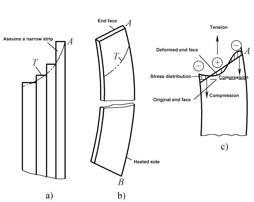
a) Imaginary deformation of the strip
b) Actual deformation of the end face
c) Stress distribution
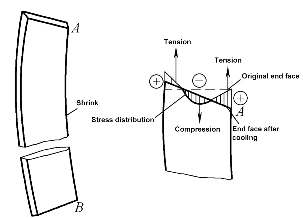
When local heating of metal in strip or circular form is performed, the patterns of stress and deformation can be similarly analyzed.
II. Characteristics of flame straightening
1) Flame straightening can achieve considerable straightening force, with obvious effects. For low carbon steel, heating just 1cm 2 area to a plastic state and then cooling can produce about 24kN of straightening force. If 0.01m 2 of material heating area on the workpiece reaches a plastic state during straightening, it will produce 2400kN of straightening force after cooling.
Therefore, flame straightening is not only used for steel materials but also more extensively for correcting deformations of various steel structures of different sizes and forms.
2) Flame straightening equipment is simple, methods are flexible, and operation is convenient. Flame straightening is used not only in the material preparation process for correcting steel plates and profiles but also widely applied in correcting various deformations of metal structures during the manufacturing process, such as in ships, vehicles, heavy frames, large containers, and correcting boxes, beams, etc.
3) Flame correction, like mechanical correction, also consumes part of the plastic reserve of metal materials, and should be used with caution for particularly important structures, brittle or poor plastic materials. The heating temperature should be properly controlled. If the temperature exceeds 850°C, the metal grains grow and mechanical properties decrease; however, too low a temperature will reduce the correction effect.
For materials prone to quenching, special care should be taken when using flame heating with water cooling.
III. Common heating methods for flame correction
According to the shape of the heating area, there are three methods: point heating, line heating, and triangular heating.
1. Point heating
Use the flame to move in a circular ring on the workpiece, evenly heating it into a circular point shape (commonly known as a fire ring), and heat one or more points as needed. When heating multiple points, they are distributed in a plum blossom shape on the plate, as shown in Figure 6-7, and are arranged in straight lines for profiles or tubes.
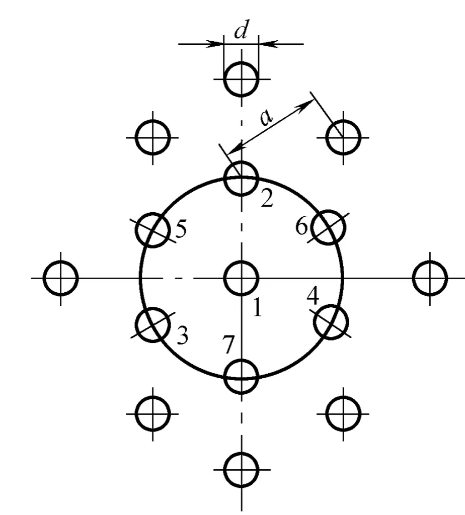
The diameter d of the heating point changes with the thickness of the plate (slightly larger for thick plates and slightly smaller for thin plates), but should generally not be less than 15mm. The distance between heating points decreases as deformation increases, generally between 50~100mm.
2. Line (strip) heating
The flame moves in a straight direction and simultaneously swings laterally to form a strip heating zone with a certain width, as shown in Figure 6-8. During line heating, lateral contraction is greater than longitudinal contraction, and the amount of contraction increases with the width of the heating zone, which is usually 0.5~2 times the thickness of the plate, generally 15~20mm.
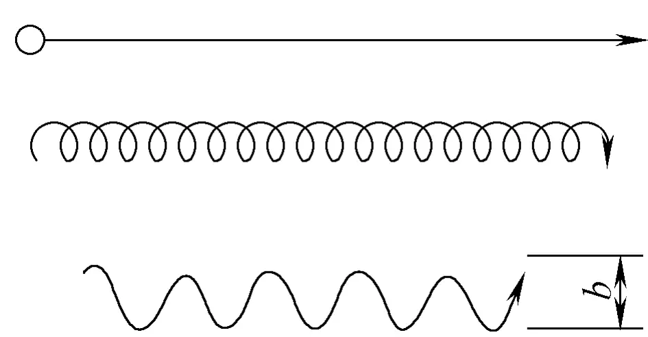
The length and spacing of the heating line depend on the size of the workpiece and the deformation situation. Linear heating is often used to correct structures with large stiffness and deformation.
3. Triangular Heating
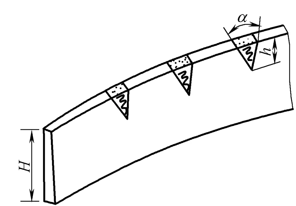
Swing the flame to make the heating area triangular, with the base of the triangle at the edge of the steel plate or profile being corrected, and the apex pointing inward, as shown in Figure 6-9. Because the triangular heating area is large, the amount of shrinkage is also large, and the heating width along the height of the triangle is not equal, the closer to the edge of the plate, the greater the shrinkage.
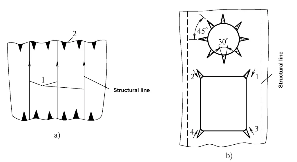
Triangular heating method is commonly used to correct deformations in components with large thickness and stiffness. For example, correcting the bending deformation of profiles and welded beams, or used to correct the wavy deformation of the free edge of the steel plate in a plate frame structure. At this time, the apex angle of the triangle is about 30°. When correcting profiles or welded beams, the height of the triangle should be 1/2 to 1/3 of the height of the web.
IV. Key Points of Flame Straightening Process
Flame heating correction of deformation is often used in metal structure manufacturing. To improve the correction efficiency and quality of the workpiece, the following points should be noted during operation:
1) Understand the material of the structure and its characteristics in advance to determine whether flame correction can be used, and correctly control the heating temperature during the correction process according to different materials to avoid severe degradation of the material’s mechanical properties due to flame correction.
2) Analyze the characteristics of the structural deformation, consider the heating method, heating position, and heating sequence, and choose the best heating scheme.
3) Use a neutral flame for heating. If a shallow heating depth is required to avoid significant angular deformation, an oxidizing flame can also be used to increase the heating speed.
4) When correcting large and complex plate and structural steel, both local and overall deformations may occur, involving both plate and structural steel deformations. During the correction process, these factors will affect each other, and it is necessary to master their deformation patterns, apply them flexibly, minimize the correction workload, improve efficiency, and ensure correction quality.
5) During flame correction, external forces can also be applied to the structure. For example, using the self-weight of large structures and added heavy objects to create additional bending moments, or using machinery for pulling and pressing, can increase the deformation of the structure.
In summary, flame correction operations are flexible and varied, with no fixed pattern. Operators should master the deformation patterns through practice, accumulate experience, and thus achieve better correction results.
V. Applications of Flame Correction
1. Correction of Steel Plate Deformation
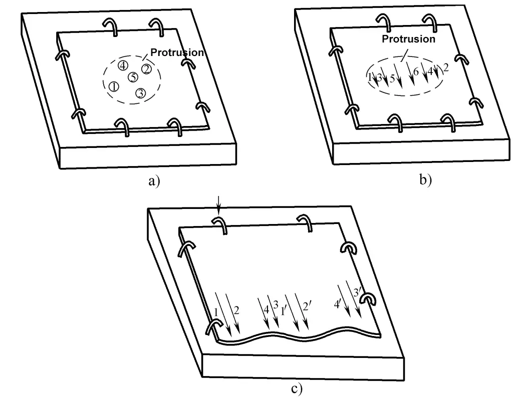
When the middle of a thin plate bulges with the surrounding area relatively flat, place the bulging side of the steel plate upwards on a platform, clamp the edges with clamps, and symmetrically heat the bulging area from the outside in, as shown in Figure 6-10a. This bulge can also be corrected by linear heating, with the sequence moving from the edges of the bulge to the center, as shown in Figure 6-10b.
When the edges of the steel plate are loose and form a wavy deformation, first clamp three sides of the steel plate on the platform with clamps, concentrating the deformation on one side of the plate, and heat linearly from both sides of the bulge towards the center, as shown in Figure 6-10c. The width, length, and spacing of the heating lines depend on the deformation.
a) Point heating of the middle bulge
b) Line-shaped heating with a central bulge
c) Heating when the edge is wavy deformed
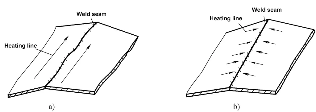
After butt joining of thin plates, longitudinal wavy deformation and angular deformation often occur at the weld. At this time, line-shaped heating should be applied on both sides along the force direction of the weld to correct the longitudinal wavy deformation, and then short line-shaped heating perpendicular to the weld direction on both sides of the weld to correct the angular deformation, as shown in Figure 6-11.
The more common deformation in thick plates is bending deformation. For correction, place the convex side up on a platform, perform line-shaped heating at the highest point, and control the heating depth to about 1/3 of the plate thickness. The purpose is to offset the bending deformation through the angular deformation caused by uneven shrinkage in the thickness direction of the steel plate. If the bending deformation disappears, the steel plate returns to flatness.
a) Correction of longitudinal wavy deformation
b) Correction of angular deformation
2. Correction of deformation in profiles and welded beams
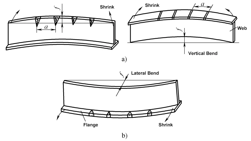
The more common deformations in profiles and welded beams are bending deformations, but sometimes there are also torsional deformations, and angular deformations of the flanges. T-beams with bending in different directions within the web plane are corrected by triangular heating on the web or strip heating on the flanges.
Bending within the plane of the flange (lateral bending) is corrected by triangular heating on the protruding side of the flange. The size and spacing of the heating area depend on the bending deflection f, as shown in Figure 6-12. If the flange has angular deformation, line-shaped heating should be applied along the back of the weld on the flange. Use a single line for minor deformations and double lines for major deformations.
a) Bending within the plane of the web
b) Bending within the plane of the flange
Bending deformation of large diameter tubes and shaft-like parts can be corrected by spot heating on the protruding side, as shown in Figure 6-13.

3. Correction of frame deformation
Large frame structures composed of plates and profiles tend to deform in various forms after assembly and welding.
Angular deformation caused by corner welds made of plates and profiles can generally be corrected by line heating on the back of the weld. When the plate is thick or the deformation is severe, external force can be applied with tools while heating.
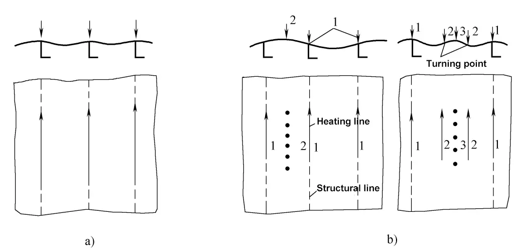
When concave and convex wave deformations occur between the profiles in the grid, first perform line heating on the back of the corner weld, and correct at the junction of the convex and concave points with long line, short line, or cross heating. If the deformation is not completely eliminated at this time, heat the middle of the protrusion. The correction of frame deformation is shown in Figure 6-14, where the numbers in the figure indicate the sequence of heating.
a) Simple angular deformation
b) Concave-convex wave deformation
When there is continuous wave deformation in adjacent panel grids, correction can be done by skipping intervals. In this case, the deformation of the middle panel grid is influenced by both sides, which can reduce the amount of correction work.
The correction of complex frame structure deformations is difficult and requires rich practical experience and skilled techniques. Generally, the deformation of the frame should be corrected first, followed by the deformation of the steel plate. When strong and weak frames are adjacent, the strong frame should be corrected first, followed by the weak frame.
If the frames are relatively weak, the correction of the panel and frame can be done alternately. When the plate thickness varies, the thick plate should be corrected first, followed by the thin plate. When correcting a certain part of the deformation, consider the impact on adjacent parts and the overall structure, and pay attention to the assembly requirements of the next process.
4. Correction of the free edge of the frame
The free edges of the frame and the periphery of each hole on the plate are prone to severe wavy folds. In this case, the frame around the hole should be corrected first, then use the triangular heating method to correct the wave deformation along the frame or hole edge, as shown in Figure 6-15.
a) Correction of the free edge of the frame
b) Correction around the hole
Correction of Large Structures
Large metal structures (such as hull sections, assembly stands) often exhibit overall warping deformations as shown by the dashed lines in Figure 6-16 after welding, and the width of the sections also changes. At this time, the sections can be placed on sleepers (with the sleepers positioned near the sides of the section, leaving the middle suspended), and heavy objects are placed in the middle of the section, then line heating is applied at the positions shown in Figure 6-16.
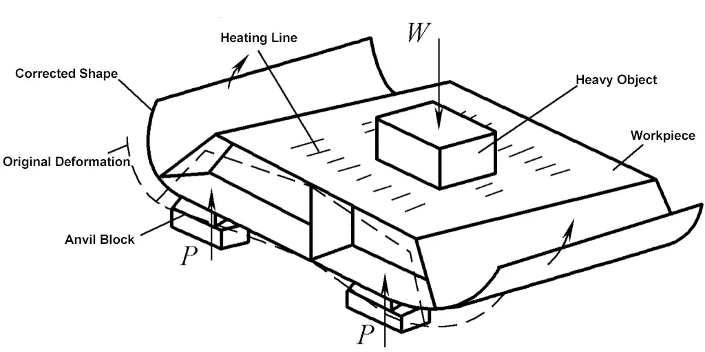
The additional bending caused by the self-weight of the section and the heavy objects can greatly enhance the effect of flame correction. When the section has opposite warping deformation, it is then flipped 180° and placed upside down on the sleepers for correction.
Section Three: Correction Skills Training
I. Correction Workpiece Diagram
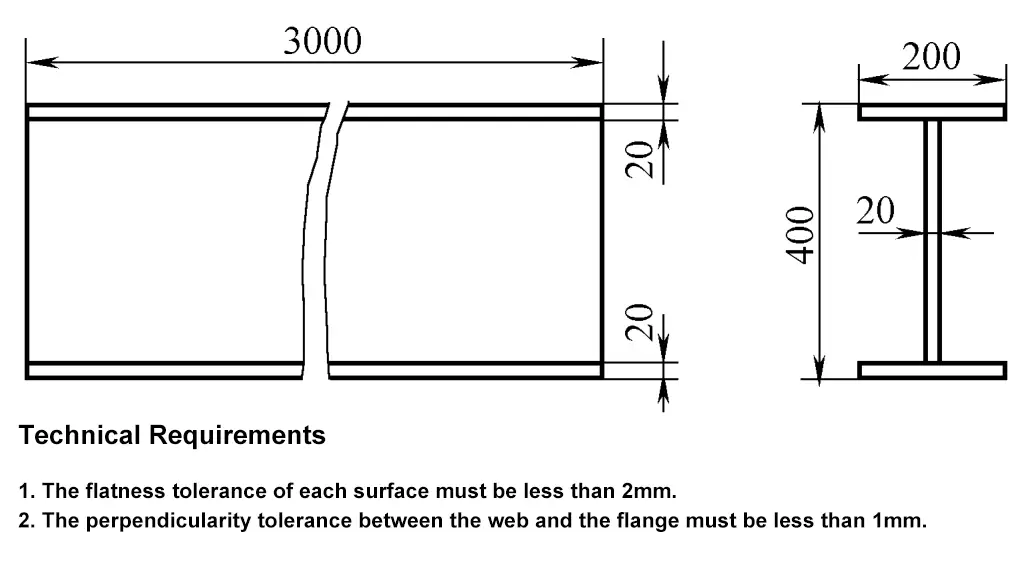
The correction workpiece diagram is shown in Figure 6-17.
II. Steps and Methods of Correction
1. Correction Preparation
1) Prepare heating tools, equipment torch (H01-20), oxygen cylinder, acetylene cylinder, pressure reducer, etc.
2) Prepare a platform of 2000mm×3000mm.
3) Prepare tools such as tension bolts, compression bolts, pressure plates, adjustable wrenches, sledgehammers, etc.
2. Correction of Twisted Deformation
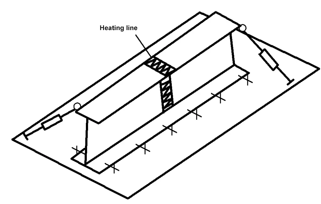
The I-beam has high rigidity, besides requiring a slightly higher heating temperature (750~800℃), correction also needs external force assistance. First, fix the I-beam on the platform and tighten it diagonally at both ends with tension bolts, then heat the upper flange in the middle of the beam. If the twist is severe, heat can also be applied to the middle web.
After heating, tighten the bolt rods to apply external force to correct the twist. If one heating is not enough to fully correct the twist, repeat the correction process, but try not to overlap the heating positions with the previous ones. Considering that the twist is an overall deformation, the heating positions should always be symmetrically distributed. As shown in Figure 6-18.
3. Correction of Bending Deformation
The bending deformation of the I-beam is divided into vertical arch (bending within the web plane) and lateral bending (bending within the flange plane). The correction of both vertical arch and lateral bending of the I-beam can be done using a triangular heating method. The heating positions should be on the outer side of the bent part of the workpiece and should be evenly distributed. For correcting the vertical arch, mainly heat the web as shown in Figure 6-19a. For correcting lateral bending, just heat the flange as shown in Figure 6-19b.
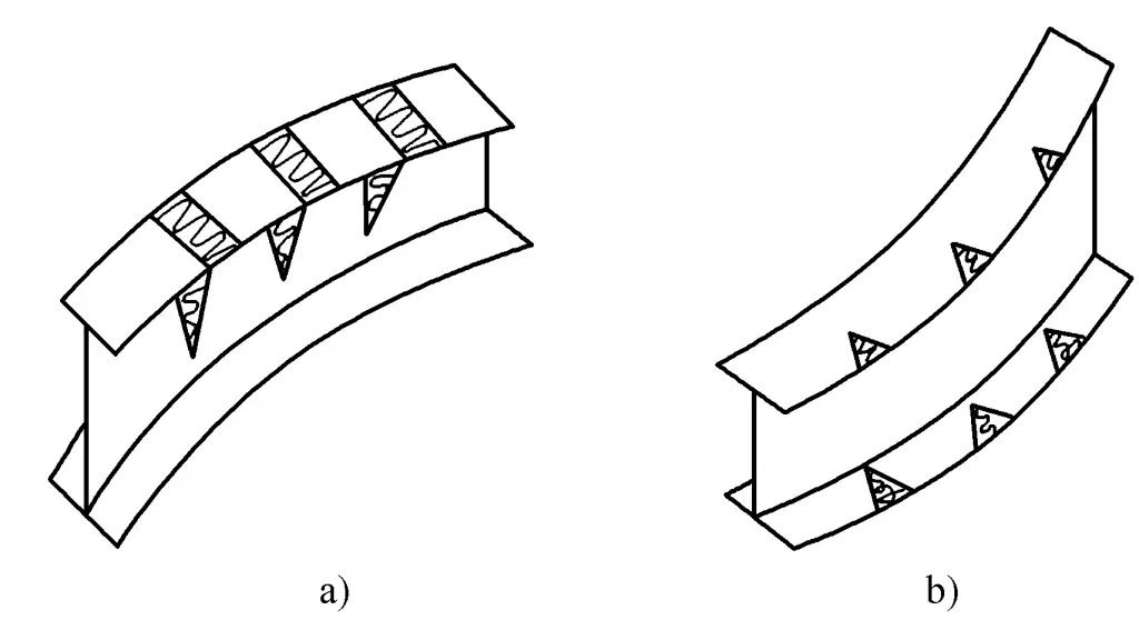
a) Correction of vertical arching
b) Correction of lateral bending
4. Inspection of correction quality
The quality of the corrected welded I-beams should meet the specifications in the “Allowable Deviations Table for Steel before Use.”

