Effective Methods to Eliminate Welding Residual Stress
Imagine meticulously welding a crucial component, only to discover later that residual stress has compromised its structural integrity. This hidden…
Although residual stress issues are considered during structural design and measures are taken in the process to prevent or reduce welding residual stress, due to the complexity of welding stress, significant residual stress may still exist after the structure is welded.
Additionally, some structures may develop new internal stresses during the assembly process. These welding residual stresses and assembly stresses can affect the performance of the structure, especially for critical welded structures. Therefore, appropriate measures should be taken to eliminate residual stresses to ensure the safety of the structure’s use. Common methods for eliminating residual stress include:
The heat treatment method uses the material’s reduced yield strength and creep phenomenon at high temperatures to relax welding residual stresses. Heat treatment also improves the performance of the weld joint. Commonly used heat treatment methods include overall high-temperature tempering and local high-temperature tempering.
Tempering temperatures for various materials are shown in Table 9-1.
Table 9-1 Tempering temperatures for various materials
| Material Type | Carbon steel and low, medium alloy steel① | Austenitic steel | Aluminum alloy | Magnesium alloy | Titanium alloy | Niobium alloy | Cast iron |
| Tempering temperature/℃ | 580~680 | 850 ~1050 | 250~300 | 250~300 | 550 ~600 | 1100 ~1200 | 600 ~650 |
After tempering low-alloy steel containing vanadium at 600~620°C, plasticity and toughness decrease, so the tempering temperature should be chosen between 550~560°C.
The high temperature holding time is determined by the thickness of the material. For steel, it is calculated at 1~2min/mm, generally not less than 30 minutes and not more than 3 hours. To uniformly raise the temperature across the thickness of the plate to the required level, a certain holding time is needed after the surface of the plate reaches the required temperature.
Heat treatment is generally carried out inside a furnace. For large containers, it can also be done by covering the outer wall of the container with an insulating layer and heating the inside with flames or electric resistance.
Figure 9-36 shows a schematic diagram of the overall heat treatment of a large spherical tank using gas flames on-site. In the diagram, the spherical tank is treated as a heating furnace, with ultra-high-speed combustion nozzles inserted from the lower manhole, using liquefied petroleum gas or city coal gas as fuel, injecting gas at a speed of 150~300m/s into the tank, using forced convection of hot air to make the gas swirl along the inner wall of the tank, evenly heating the tank wall.
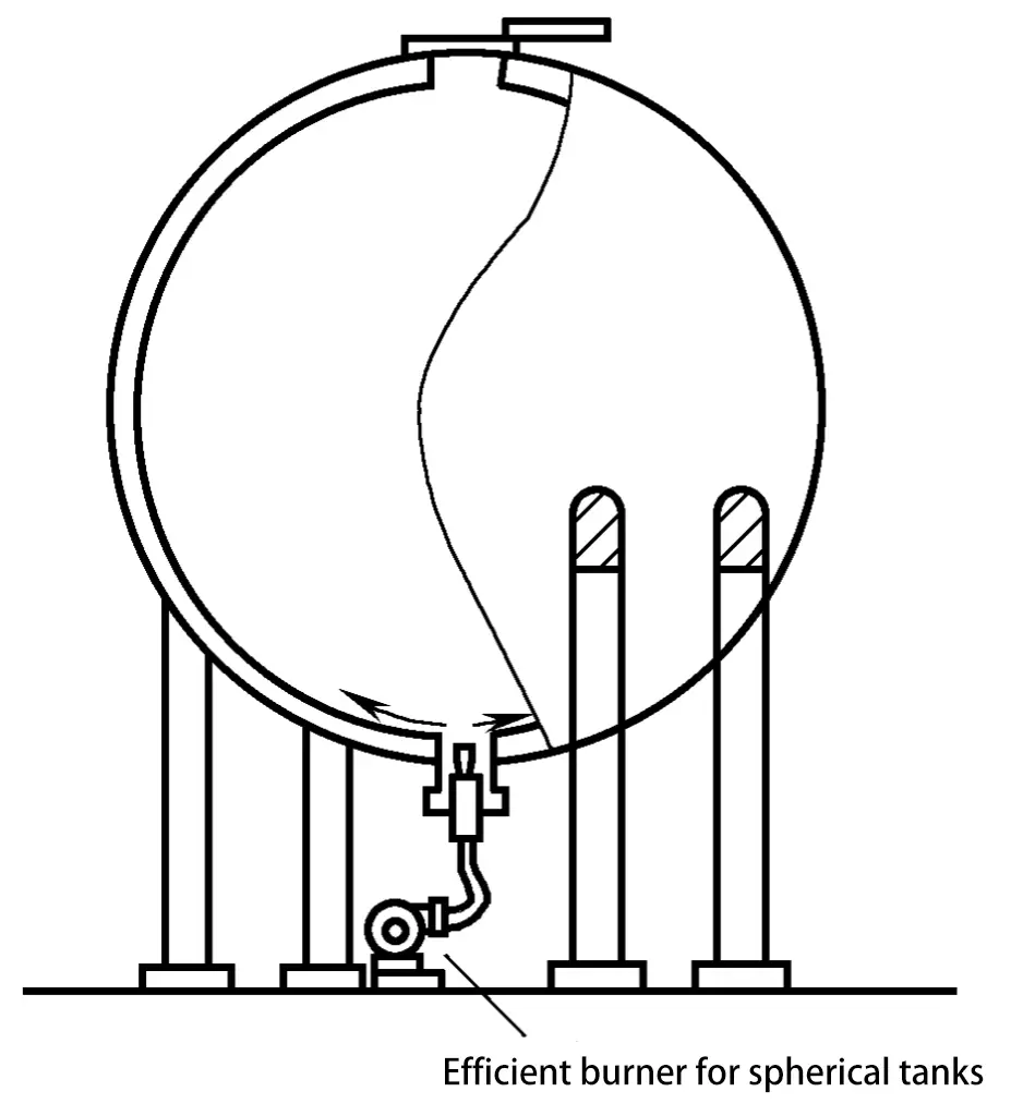
The temperature is regulated by controlling the gas flow, air volume, injection angle, and the opening of the exhaust gate. Exhaust gases are discharged from the top opening. An insulation layer is placed on the outer surface of the tank (not shown in the diagram) to prevent heat diffusion. A thermocouple is placed every 4~5m on the outer surface of the sphere to monitor the wall temperature.
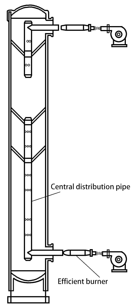
The same method can also be applied to the on-site heat treatment of vertical elongated containers (tower containers), as shown in Figure 9-37. Since this container has a tall and slender shape, achieving a uniform distribution of heating temperature is challenging, thus the number of burners is appropriately increased, and hot air is sprayed from the small holes of the centrally inserted distribution pipe.
Overall high-temperature tempering can eliminate 80%~90% of residual stresses.
Heat the weld and its nearby high-stress areas to the high-temperature tempering temperature, then hold the temperature and slowly cool. This is often used for joints that are relatively simple in shape and have low restraint, such as pipe joints, long cylindrical container joints, and long component butt joints. Local high-temperature tempering can be done using resistance, infrared, flame, and industrial frequency induction heating.
Local high temperature tempering cannot completely eliminate residual stress, but can reduce its peak to make the distribution of stress more gradual. The effect of stress relief depends on the uniformity of temperature distribution in the local area. To achieve a better stress reduction effect, sufficient heating width should be maintained.
For example: The heating zone width of the cylindrical joint is generally taken from the formula in the figure, and for long plate butt joints, B=W is taken as shown in Figure 9-38 (R is the radius of the cylinder, δ is the wall thickness, B is the width of the heating zone, W is the width of the butt component).
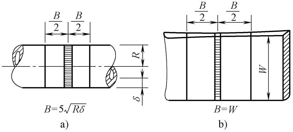
a) Circumferential weld b) Long component butt weld
After welding, load the welded components to cause tensile plastic deformation in areas with higher tensile residual stress, and unloading can reduce the welding residual stress. The higher the loading stress, the more the compressive plastic deformation formed during the welding process is offset, and the more thoroughly the internal stress is eliminated.
The mechanical stretching method is particularly meaningful for eliminating internal stress in some welded containers. It can eliminate some welding residual stresses by performing an overload endurance test at room temperature.
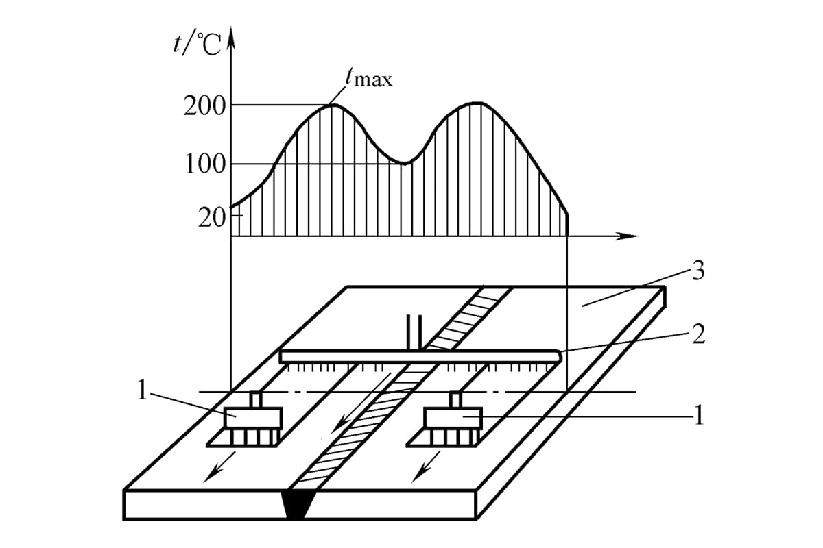
Heat each side of the weld with an oxy-acetylene torch to about 200°C. Cool with water spray at a certain distance behind the torch. The torch and water spray move forward at the same speed (see Figure 9-39). This creates a temperature differential with the sides being high (about 200°C) and the weld zone low (about 100°C). The metal on the sides expands due to heating, stretching the cooler welded area, causing tensile plastic deformation to offset the original compressive plastic deformation, thereby eliminating some of the stress. Parameters for the thermal differential stretching method are shown in Table 9-2.
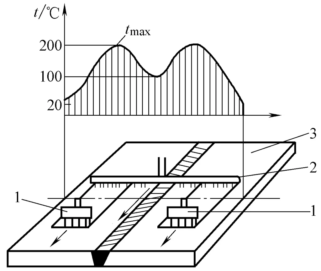
1—Flame heating torch
2—Water spray pipe
3—Weldment
Table 9-2 Parameters of Thermal Expansion Method
| Steel plate thickness /mm | Heating width /mm | Distance from the center of the welding torch /mm | Torch moving speed / (mm/min) |
| 8 | 60 | 115 | 600 |
| 10 | 100 | 125 | 400 |
| 15 | 100 | 180 | 500 |
| 17 | 100 | 180 | 300 |
| 20 | 100 | 180 | 250 |
| 25 | 100 | 180 | 200 |
| 30 | 100 | 180 | 175 |
| 35 | 100 | 180 | 150 |
| 40 | 100 | 180 | 125 |
When the nozzle width is 100mm, the acetylene consumption of each nozzle is 17m³/h, the water consumption is 5~6L/min, and the distance between the flame nozzle and the water pipe is 130mm.
The thermal expansion method is commonly used for welds that are relatively regular and not very thick (<40mm) in vessels, ships, and other plate and shell structures. It has practical value. If the process parameters are chosen appropriately, good stress relief effects can be achieved.
After welding, hammering the weld with a hammer or a hemispherical air hammer of a certain diameter can cause the weld metal to undergo elongation deformation, which can offset some of the compressive plastic deformation and reduce welding stress. Care should be taken during hammering to apply moderate force to avoid cracks due to excessive force.
The vibration method, also known as vibration aging or stress relief by vibration (VSR), uses an exciter composed of an eccentric wheel and a variable speed motor to cause the structure to resonate, using the cyclic stress generated by resonance to reduce internal stress. Its effectiveness depends on the exciter, the position of the workpiece supports, the vibration frequency, and duration.
The equipment used in the vibration method is simple and inexpensive, energy-saving, with low processing costs and short duration (from a few minutes to several tens of minutes), and it does not cause issues like oxidation of the metal surface during high-temperature tempering. Therefore, it is currently more commonly used in weldments, castings, and forgings to improve dimensional stability.
1) Vibration aging mechanism.
From the perspective of atomic theory, when the temperature is above absolute zero, metal atoms are always in motion. Due to the influence of residual stress, these atoms are in an unbalanced state, but they strive to return to their original positions, which requires energy. Vibration aging is the application of a certain amount of mechanical energy to the workpiece, forcing the residual stress that constrains the metal atoms to be released, and accelerating the speed at which the metal atoms return to equilibrium positions.
In other words, vibration aging is achieved by applying periodic dynamic stress to the workpiece, forcing it to vibrate within its resonance range; during the vibration process, the dynamic stress applied to various positions of the workpiece is superimposed with the internal residual stress. If the sum of the dynamic stress amplitude and the residual stress at certain points of the workpiece exceeds the yield strength, i.e., σ0 + σ1 > σ2, these points will undergo minor plastic deformation, allowing the residual stress to be released.
Similarly, if this dynamic stress causes lattice slip at certain points of the workpiece, although it is still far from the macroscopic yield strength of the material, these points will still undergo minor plastic deformation at the microscopic level, and these plastic deformations often occur first at the places where the residual stress is most concentrated, thus achieving the purpose of releasing and reducing residual stress.
2) Applicability of vibration aging.
Applicable materials. Suitable for carbon structural steel, stainless steel, cast iron, aluminum alloy, copper alloy, and materials that have been induction heated surface hardened and quenched.
Objects of treatment. It can treat various mechanical product base parts, castings, forgings, welded parts, rough machined structural parts, workpieces requiring dimension stability before and after cold and hot straightening, long and large diameter shaft parts, and various metal parts with strict precision requirements, as well as oversized workpieces that cannot undergo thermal aging treatment.
Flexible processing procedures. It is often performed after forging, casting, welding, rough machining, and surface hardening processes, and can also be done before the final precision machining is completed.
It can even be tailored to the special needs of the workpiece, determining the aging sequence and frequency at different processes (such as one-time vibration, two-time vibration). It can treat large workpieces individually or use a platform method for centralized mixed treatment of small parts, and is not limited by the shape, weight, size, volume, batch, location, or time of the workpiece. The weight of the workpieces treated can range from a few kilograms to over a hundred tons.
3) Method for evaluating the effectiveness of aging.
According to the JB/T5926-2005 standard, if one of the situations shown in Figure 9-40 occurs, it can be determined that the aging process effect has been achieved.
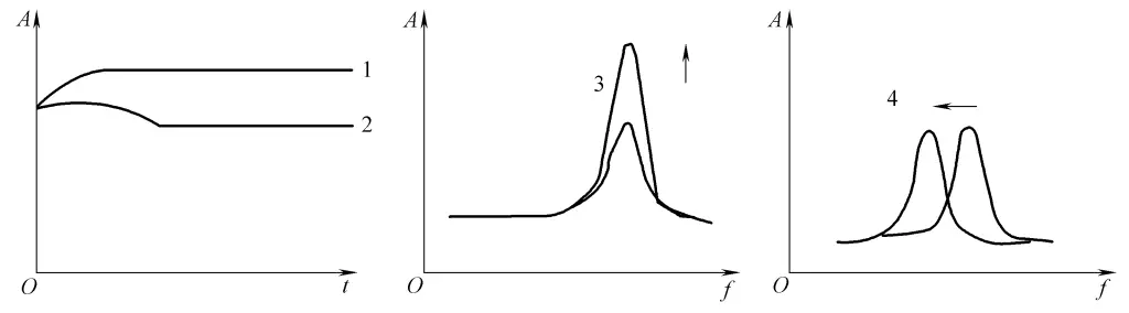
1—Amplitude-Time (A-t) curve rises then flattens
2—Amplitude-Time (A-t) curve rises then falls and then flattens
3—Amplitude-Frequency (A-f) curve post-vibration peak is higher than pre-vibration
4—Amplitude-Frequency (A-f) curve post-vibration peak shifts left compared to pre-vibration peak
Vibration stress relief equipment is produced by professional manufacturers in China, and has been basically standardized and increasingly perfected. Pay attention to the following points when using it.
1) Selection of the component to be vibrated.
The most economical and efficient method is resonance treatment. To achieve resonance conditions, it is first required that the natural frequency of the workpiece to be vibrated is within the frequency range that the vibrator can achieve. The frequency range of a standardized vibrator is fixed, and if the natural frequency of the workpiece exceeds this range, it is difficult to achieve the desired effect.
2) Installation position of the vibrator.
The vibrator is generally installed at the peak of the workpiece’s vibration, as shown in Figure 9-41. This allows the workpiece to be excited with the least amount of energy to produce significant vibration. The peak position can be roughly determined by trial vibration, by feel, or by sprinkling sand.
The determined position should ensure that the workpiece remains stable during the vibration process. Do not install directly on the thin plate of the workpiece or at parts with reinforcing ribs, to prevent the workpiece from cracking during vibration. For large components, to achieve better vibration effects, the installation position can be changed according to the specific situation of the structure for vibration treatment.
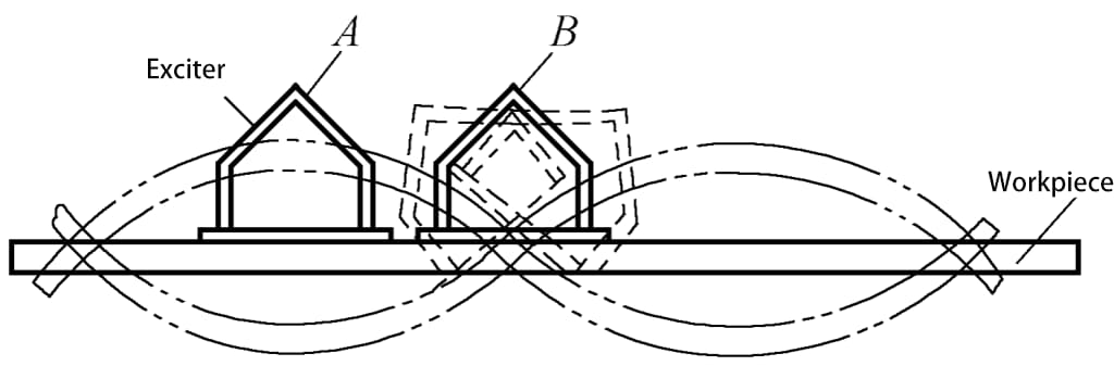
A—Correct B—Incorrect
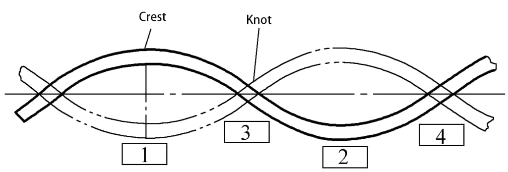
3) The support position of the workpiece.
Generally, the welded parts, which have cooled down (sometimes still hot), are placed on a vibration table and supported with pads. The pads are often made of rubber or old tires and other elastic materials. The support positions are chosen as close as possible to the nodes of vibration to prevent energy loss and noise caused by the collision between the workpiece and the support pads during vibration. The fewer the supports while maintaining stable vibration of the workpiece, the better.
Figure 9-42 shows a schematic diagram of the support during the vibration treatment of the workpiece. It is reasonable to choose the support positions at points 3 and 4, as the vibration is more stable and the noise is lower. If chosen at points 1 and 2, the energy transmitted to the workpiece during vibration is reduced, while the noise and ground vibration increase.
Once the type of workpiece, vibration point, and support position are determined, it is necessary to control the vibration frequency, amplitude, and duration during vibration.
The best resonance effect occurs at the natural frequency of the workpiece. Therefore, the natural frequency of the workpiece should be determined first (e.g., by tapping or resonance methods) and used as the vibration frequency. The cyclically varying dynamic stress applied to the workpiece by the vibrator during the vibration process is a decisive parameter for reducing residual stress, as it must combine with the residual internal stress to produce plastic deformation to reduce stress.
If the residual stress of the workpiece is small, a sufficiently large dynamic stress must be used to reduce the residual stress. Conversely, when the residual internal stress is large, a smaller dynamic stress can be chosen. Therefore, it is necessary to measure or estimate the magnitude and distribution of the residual internal stress in the weldment first.
Moreover, it is important to ensure that the maximum value of the residual stress combined with the additional dynamic stress does not exceed the fatigue strength during vibration or operation, otherwise damage may occur during the vibration or operational process.
In special cases where higher dynamic stress cannot be used, lower dynamic stress can be applied with an appropriate extension of vibration time. The magnitude of dynamic stress can be adjusted by the size of the excitation force. Since the amplitude is related to the excitation force, when the vibration frequency and system damping are constant, a larger excitation force results in a larger amplitude, thereby imparting greater dynamic stress to the workpiece.
Due to the different structural forms and weights of the weldments, the magnitude and distribution of residual stresses vary, so the selection of vibration time should also be different. It is usually determined approximately by the mass of the workpiece, as shown in Table 9-3.
Table 9-3 Vibration time for stress relief by vibration method
| Component Quality/kg | 227 | 227~907 | 907 ~4536 | >4536 |
| Vibration time/min | 5 ~10 | 10 ~ 20 | 20 ~30 | 30 ~45 |
On-site operations cannot determine the effect of eliminating residual stress. It is often judged based on some physical phenomena of the vibration process, such as observing changes in stride curves, resonance frequency, and excitation power changes. Currently, changes in excitation power are mostly observed, the main basis being that the component continues to vibrate under the action of excitation energy. When the component undergoes plastic deformation, its residual stress is relaxed, and the metal material is strengthened.
The result is a reduction in structural damping, which allows more excitation energy to be consumed in the displacement of component vibration (i.e., amplitude) rather than being consumed in internal damping. Therefore, when vibrating components with residual internal stress, if the excitation energy is kept constant, an increase in amplitude value will occur. If the amplitude value is controlled to remain constant, the required excitation energy will decrease, reducing power.
The method of stress relief through vibration has many advantages, but there are also some concerning issues that have not been fully resolved, such as how to ensure that internal stresses are uniformly reduced in complex welded structures; and how to control the vibration so that it can eliminate internal stresses without reducing the fatigue strength of the structure.
Explosion bonding is achieved by arranging explosive strips at and near the weld, where the shock waves generated by detonation interact with residual stresses, causing the metal to undergo an appropriate amount of plastic deformation, thereby relaxing the residual stresses. The amount of explosives per unit length of the weld and the arrangement should be selected based on the thickness of the welded parts and the material properties.
Figure 9-43 shows the explosive charge layout used for relieving welding stress in large, medium-thick plate welded structures. Flat plate butt joints are typically charged in the areas of residual tensile stress from welding, while curved plate butt joints (such as welds on vessels or pipes) can be charged on both inner and outer surfaces. Studies indicate that charging in the areas of residual tensile stress on the inner surface of curved plates has a more significant effect than charging on the outer surface.
When it is difficult to apply medicine on the inner surface, exploding medicine at appropriate positions on both sides of the outer surface weld can also achieve the effect of reducing residual stress. Strip rubber explosives are generally used, with a detonation velocity of 5000m/s, detonated by a detonator.
The explosion method to eliminate welding stress has been applied in domestic pressure vessels, chemical reaction towers, pipelines, hydraulic structures, and box beams. However, explosion construction operations must be strictly carried out in accordance with relevant national regulations, adhere strictly to operating procedures, and control the amount of explosives used each time to ensure safety.