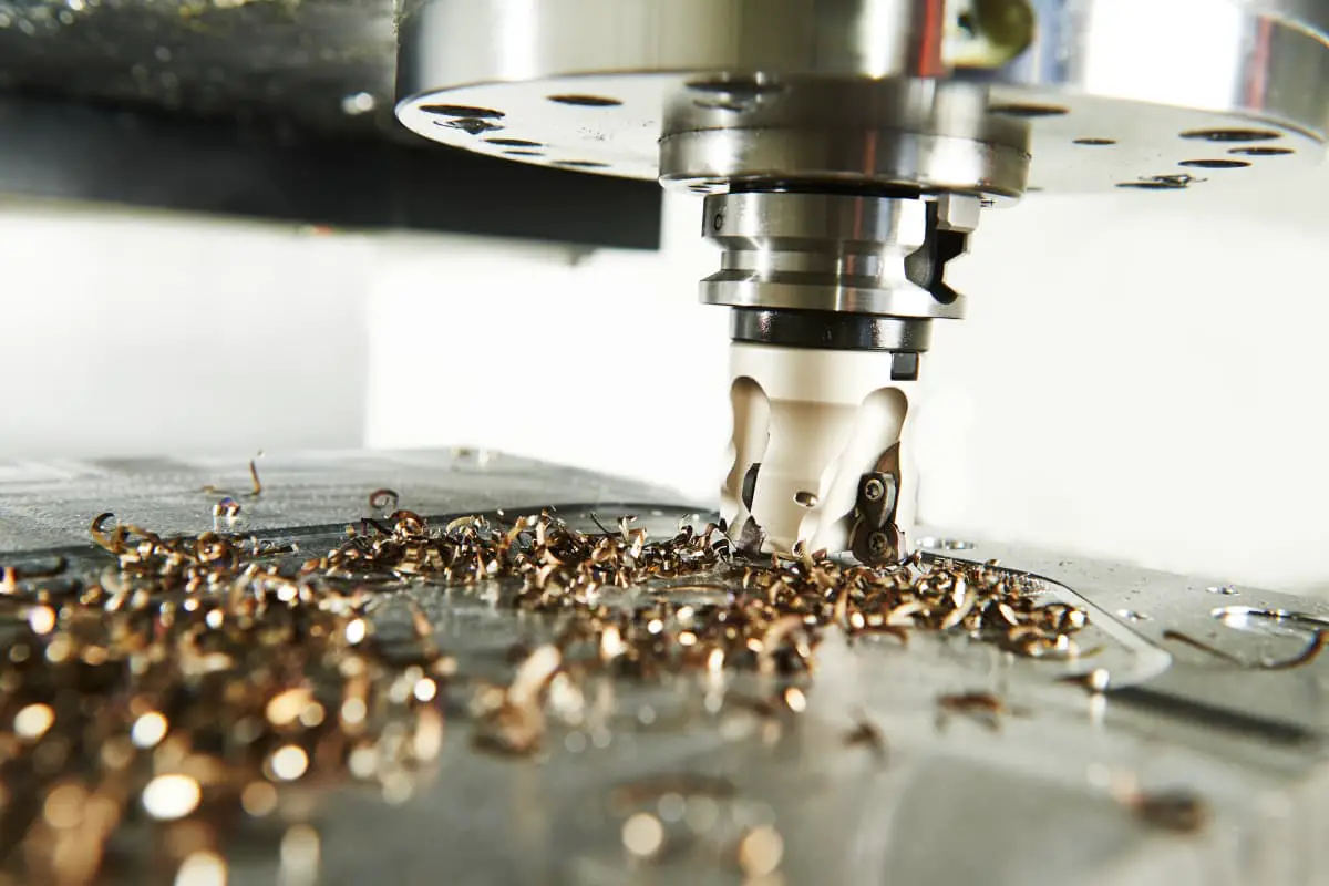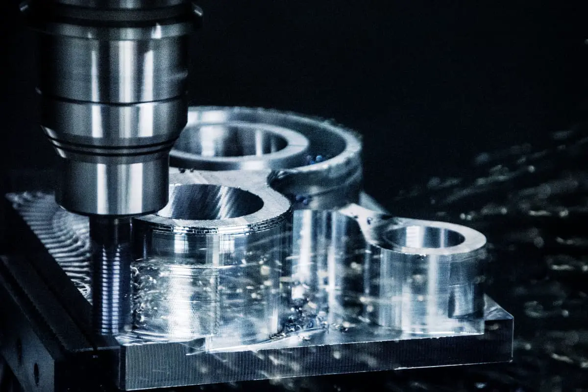
Milling processing is a method of cutting workpieces on a milling machine using a rotating multi-blade tool, which is the most basic method for processing planes and grooves. During milling, the rotation of the milling cutter is the main motion, and the linear motion or rotary motion of the milling cutter or workpiece along the coordinate direction is the feed motion.
The milling cutter is a multi-blade tool, each of its teeth is equivalent to a lathe tool, and multiple teeth participate in cutting during milling processing. For a single tooth, its cutting characteristics are basically the same as turning, but the cutting process of the entire tool has its unique aspects.
I. Overview of Milling
1. Characteristics of Milling Processing
(1) High productivity in milling processing
During milling, due to the participation of multiple teeth in cutting, the metal removal rate is high, the cutting process of each tooth is discontinuous, and the tool body is relatively large, therefore, the heat dissipation and heat transfer conditions are better, milling speed can be higher, and other cutting parameters can also be larger, hence the productivity of milling is very high.
(2) Milling processing is intermittent cutting
During milling, each tooth cuts into and out of the workpiece in turn, forming intermittent cutting, and the cutting thickness of each tooth varies, causing large variations in cutting force, and the workpiece and tooth are subjected to periodic impacts and vibrations. Milling is in a state of vibration and instability, which requires the machine tool and fixture to have high rigidity and anti-vibration capabilities.
The heat, impact, and vibration of milling can reduce tool life and affect the surface quality of machining, generally speaking, milling mainly belongs to the category of rough and semi-finish machining.
(3) Chip holding and chip removal issues
Since the milling cutter is a multi-blade tool, the chip space and chip holding space of the teeth are semi-closed, the space between adjacent teeth is limited, therefore, it is required that the chips cut by each tooth must have enough space to accommodate and be able to be removed smoothly, otherwise it will cause tool damage.
(4) The same machined surface can be milled using different methods and tools
The same shaped machined surface can be processed with different milling cutters and milling methods when milling. For example, when milling a plane, cylindrical milling cutters, end milling cutters, face milling cutters, etc., can be used, and either climb milling or conventional milling methods can be adopted. This can meet the requirements of different workpiece materials and other cutting conditions, to improve cutting efficiency and tool life.
2. Milling Process Range
The milling processing range is very wide, as shown in Figure 1. With different types of milling cutters, it is possible to process planes, step surfaces, grooves, and shaped surfaces, etc. In addition, hole processing tools such as drills, reamers, and boring tools can also be installed on the milling machine to process holes on the workpiece.
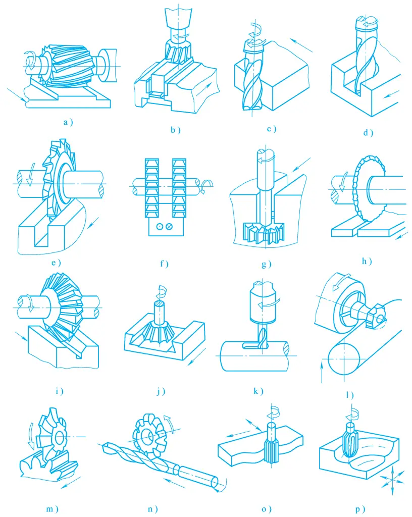
a), b), c) Milling planes
d), e) Milling grooves
f) Milling steps
g) Milling T-slots
h) Milling slots
i), j) Milling corners
k), l) Milling keyways
m) Milling gear teeth
n) Milling spiral grooves
o) Milling curved surfaces
p) Milling three-dimensional curved surfaces
Milling can be used for rough machining, semi-finishing, or finishing of workpieces. The dimensional tolerance grade of milling processing is generally IT7~IT13, and the surface roughness Ra value is 12.5~1.6μm. Milling is not only suitable for single-piece and small-batch production but also for mass production.
3. Milling Parameters
During milling, the layer of metal between two transitional surfaces formed successively on the workpiece by adjacent teeth on the milling cutter is called the cutting layer. The milling parameters determine the shape and size of the cutting layer, which has a significant impact on the milling process.
According to the different distribution positions of the cutting edges on the milling cutter, milling can be divided into peripheral milling and face milling. Milling with teeth distributed on the cylindrical surface of the milling cutter is called peripheral milling, and milling with teeth distributed on the end face of the milling cutter is called face milling, as shown in Figure 2. The milling parameters include the following milling elements.
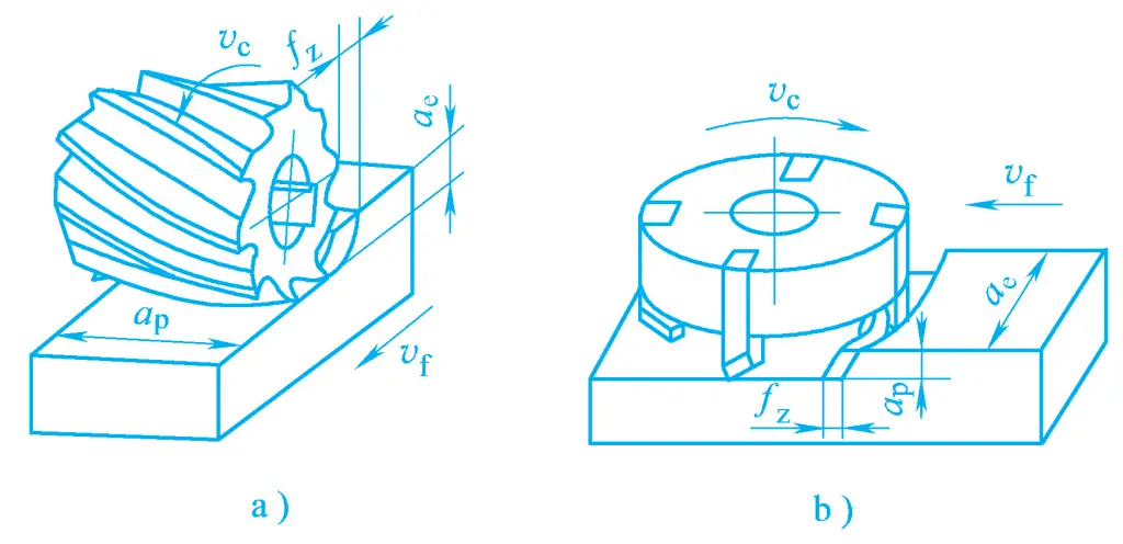
a) Peripheral milling
b) Face milling
(1) Milling Speed Vc
Milling speed is the linear speed of the milling cutter rotation, that is, the instantaneous speed of a selected point on the milling cutter cutting edge relative to the workpiece in the main motion direction, which can be calculated by the following formula:
Vc=πdn/1000
Where
- V c – Milling speed (m/min or m/s);
- d- Milling cutter diameter (mm);
- n- Milling cutter rotation speed (r/min or r/s).
(2) Feed Rate
During milling, the relative displacement of the workpiece and the milling cutter in the feed direction is called the feed rate, which has three representation methods:
1) Feed per tooth fz
The relative displacement of the milling cutter relative to the workpiece in the feed direction when each tooth of the milling cutter rotates, measured in mm/z.
2) Feed per revolution f
Refers to the relative displacement of the milling cutter relative to the workpiece in the feed direction when the milling cutter makes one complete revolution, measured in mm/r. The relationship between feed per tooth and feed per revolution is as follows:
fz=f/z
Where z is the number of teeth on the milling cutter.
3) Feed speed Vf
The relative displacement of the workpiece and the milling cutter in the feed direction per unit of time, measured in mm/min. The relationship between them is as follows:
Vf=fn =fzzn
Where n is the milling cutter speed (r/min).
(3) Axial depth of cut ap
Refers to the size of the cutting layer measured parallel to the axis of the milling cutter. For end milling, ap is the depth of the cutting layer; for peripheral milling, ap is the width of the surface being machined.
(4) Radial depth of cut ae
Refers to the size of the cutting layer measured perpendicular to the axis of the milling cutter. For end milling, a e is the width of the surface being machined; for peripheral milling, ae is the depth of the cutting layer.
II. Milling Machines
There are many types and forms of milling machines, among which lifting table milling machines, non-lifting table milling machines, and gantry milling machines are basic types. To adapt to different machining objects and production types, many derivative varieties of milling machines have been developed, such as rocker and slide milling machines, tool milling machines, profile milling machines, etc. In addition, there are various specialized milling machines, such as drill milling machines, crankshaft milling machines, etc. Below is a brief introduction to common types of milling machines.
1. Lifting table milling machine
The characteristic of this type of machine tool is that it has a lifting table that can move up and down along the vertical guide rails of the bed, and the worktable can adjust its position and complete feed motion in three mutually perpendicular directions. This type of machine tool is widely used, mainly for processing medium and small workpieces in single-piece and small-batch production. Common lifting table milling machines include the following types:
(1) Horizontal lifting table milling machine
The spindle of the horizontal lifting table milling machine is arranged horizontally, and its appearance and components are shown in Figure 3. The bed 1 is fixed on the base 8, containing the main motion’s speed change, control mechanisms, and the spindle 3. The lifting table 7 moves up and down along the vertical guide rails of the bed, the saddle 6 moves laterally on the lifting table 7, and the worktable 5 can perform longitudinal feed motion on the saddle. The lifting table, worktable, and saddle can all move quickly.
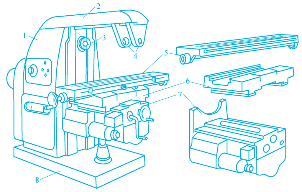
1—Bed
2—Beam
3—Spindle
4—Tool post support
5—Worktable
6—Saddle
7—Lifting table
8—Base
(2) Horizontal universal lifting table milling machine
The difference between the horizontal universal lifting table milling machine and the horizontal lifting table milling machine is that there is a rotary table on the saddle, and the worktable moves longitudinally in the guide rails on the rotary table. The rotary table can rotate around the vertical axis within a ±45° range, thereby expanding the technological range of the milling machine.
The X6132 model milling machine is a commonly used horizontal universal lifting table milling machine, and its appearance is shown in Figure 4. This machine tool has a relatively complete structure, a wide range of speed changes, good rigidity, convenient operation, and an automatic adjustment device for longitudinal feed clearance.
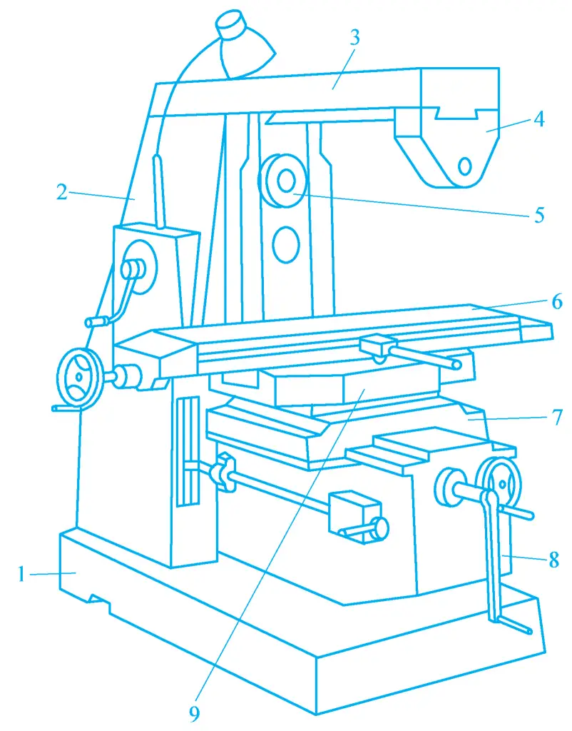
1—Base
2—Bed body
3—Hanging beam
4—Knife bar bracket
5—Main spindle
6—Workbench
7—Bed saddle
8—Lifting table
9—Rotary table
(3) Universal rotary head milling machine
The universal rotary head milling machine is structurally similar to the horizontal lifting table milling machine, as shown in Figure 5. It is essentially a horizontal milling machine, but at both ends of its slide 2, an electric motor 1 and a universal vertical milling head 3 are installed, whose milling head can be tilted in any direction to perform milling operations.
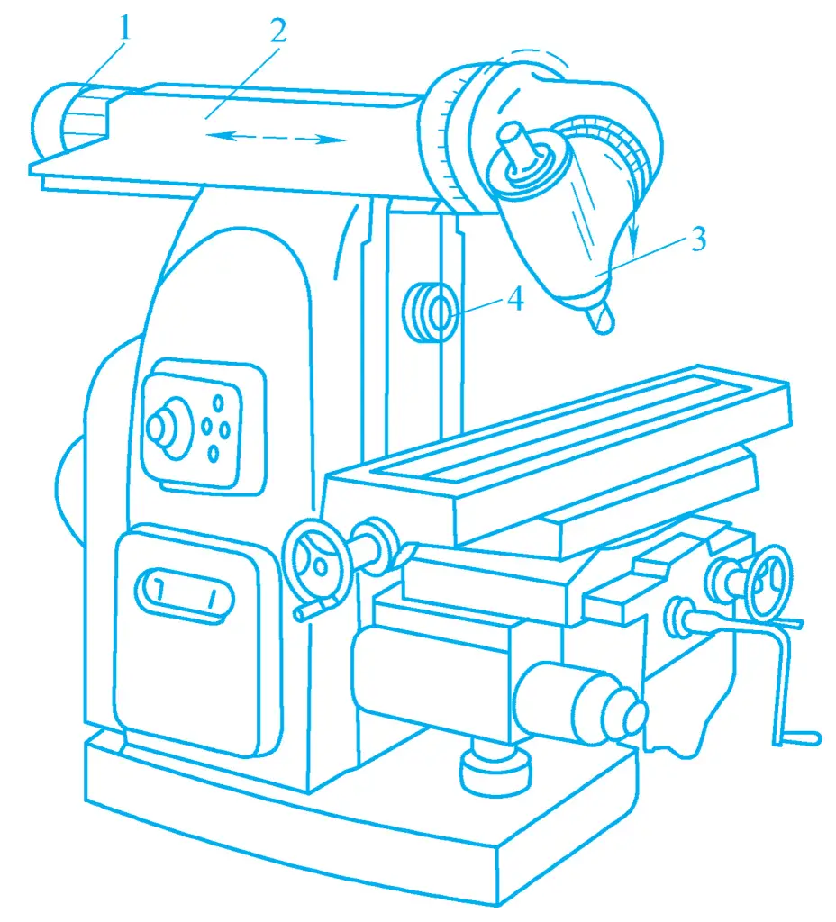
1—Electric motor
2—Slide
3—Universal vertical milling head
4—Horizontal main spindle
(4) Vertical lifting table milling machine
The biggest difference between the vertical lifting table milling machine and the horizontal lifting table milling machine is that the spindle is arranged vertically, as shown in Figure 6. The vertical milling head of the vertical lifting table milling machine can rotate to the right or left within a ±45° range in the vertical plane, to expand the machining range of the milling machine.
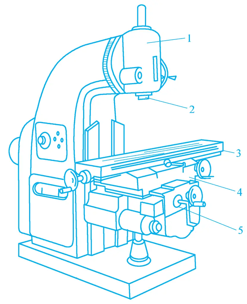
1—Milling head
2—Main spindle
3—Workbench
4—Saddle
5—Lifting table
2. Milling machine without lifting table
This type of milling machine’s workbench can only move longitudinally and laterally on a fixed base (rectangular workbench) or rotate around a vertical axis (circular workbench), with vertical adjustment and feed motion completed by the machine’s main spindle box. It has better rigidity and vibration resistance than the lifting table milling machine, suitable for processing with larger cutting amounts. Figure 7 shows the appearance of the milling machine without a lifting table.
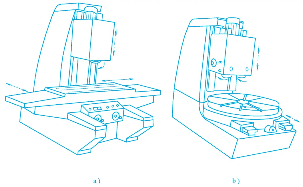
a) Workbench movement
b) Workbench rotation
3. Gantry milling machine
The gantry milling machine is a large, high-efficiency, universal milling machine, mainly used for processing various large workpieces such as planes, grooves, etc. It can perform rough milling, semi-finish milling, and also finish milling. Figure 8 shows the appearance of the gantry milling machine.
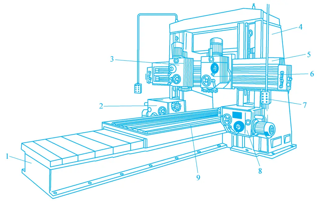
1—Bed
2, 8—Horizontal milling head
3, 6—Vertical milling head
4—Column
5—Crossbeam
The machine tool has a frame structure, the beam 5 can move up and down on the column 4 to accommodate the height of the workpiece. Two vertical milling spindle boxes (vertical milling heads) 3 and 6 are mounted on the beam. Two horizontal milling heads 2 and 8 are mounted on the two columns, respectively, each milling head is an independent component, containing the main motion speed change mechanism, spindle, and operating mechanism.
The flange-type main motor is fixed at the end of the milling spindle box. The worktable can move longitudinally horizontally on the bed 1. The vertical milling head can move horizontally across the beam, and the horizontal milling head can move up and down on the column.
All these movements can be feed movements, or they can be rapid positioning movements to adjust the relative position between the milling head and the workpiece. The spindle is mounted inside the spindle sleeve and can be manually extended or retracted to adjust the back cutting amount. 7 is a pendant button station.
Gantry milling machines can use multiple milling heads to machine several surfaces of a workpiece or machine several workpieces at the same time, so the productivity is very high, and they are widely used in batch and mass production.
III. Common Milling Machine Accessories
1. Universal dividing head
The universal dividing head is an important accessory of the milling machine (see figure 9), used to expand the machining range of the milling machine. When machining certain workpieces (such as gears, spline shafts, workpieces with spiral grooves, etc.) on the milling machine, the universal dividing head is used, and its base is fixed on the milling machine worktable. There is a rotating body on the base, and the side of the rotating body has a dividing plate, with several circles of equally divided small holes on both sides of the dividing plate.
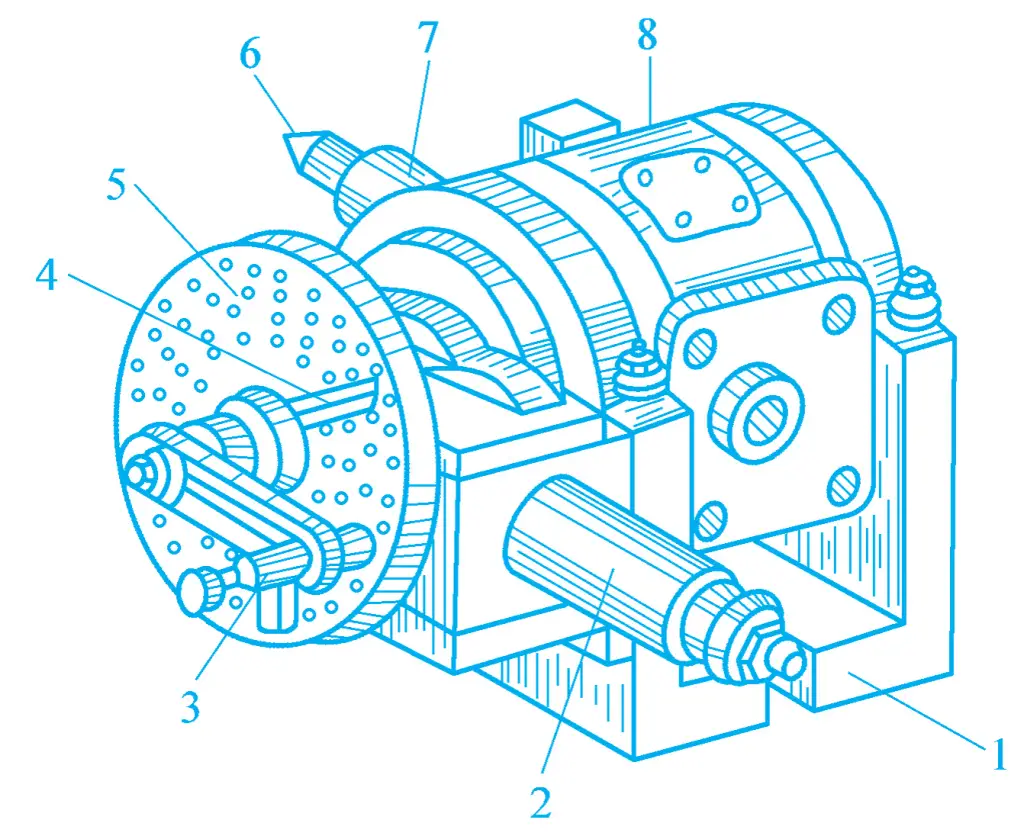
1—Base
2—Side shaft
3—Handle
4—Dividing scale
5—Dividing plate
6—Center tip
7—Spindle
8—Rotating body
By turning the handle, the internal transmission mechanism of the universal dividing head drives the spindle to rotate. The spindle can rotate at any angle between -6° and 90° with the rotating body, thus the workpiece can be inclined at the required angle relative to the worktable surface. The front end of the spindle has a standard taper hole, which can insert the center tip, and the exterior has threads for mounting chucks, dial plates, and collet chucks to hold different workpieces.
The number of circles and holes that the handle should turn on the universal dividing plate can be calculated according to the needs of the workpiece machining, to complete the equal or unequal division of the workpiece. The workpiece is supported between the center tip on the spindle of the dividing head and the center tip on the tailstock mounted on the worktable, or it can be machined using a chuck, as shown in figure 10.
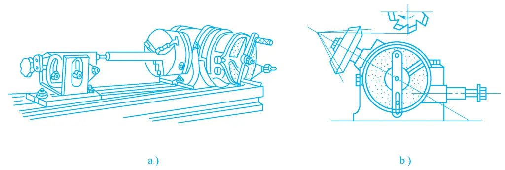
a) Clamping method for long shafts
b) Clamping method for bevel gears
In addition, by equipping a set of exchange gears between the side shaft of the universal dividing head and the feed screw of the worktable, the rotation of the universal dividing head spindle is driven by the worktable feed screw at a certain transmission ratio, thus the longitudinal feed motion of the worktable and the rotational motion of the universal dividing head spindle are combined to form a helical motion for machining spiral grooves.
2. Vertical milling head
The vertical milling head (see figure 11) is mounted on a horizontal milling machine, allowing the horizontal milling machine to function as a vertical milling machine, thus expanding its machining range. The vertical milling head can rotate 360° in the vertical plane, and its spindle speed is generally the same as that of the milling machine spindle, with a transmission ratio of 1:1.
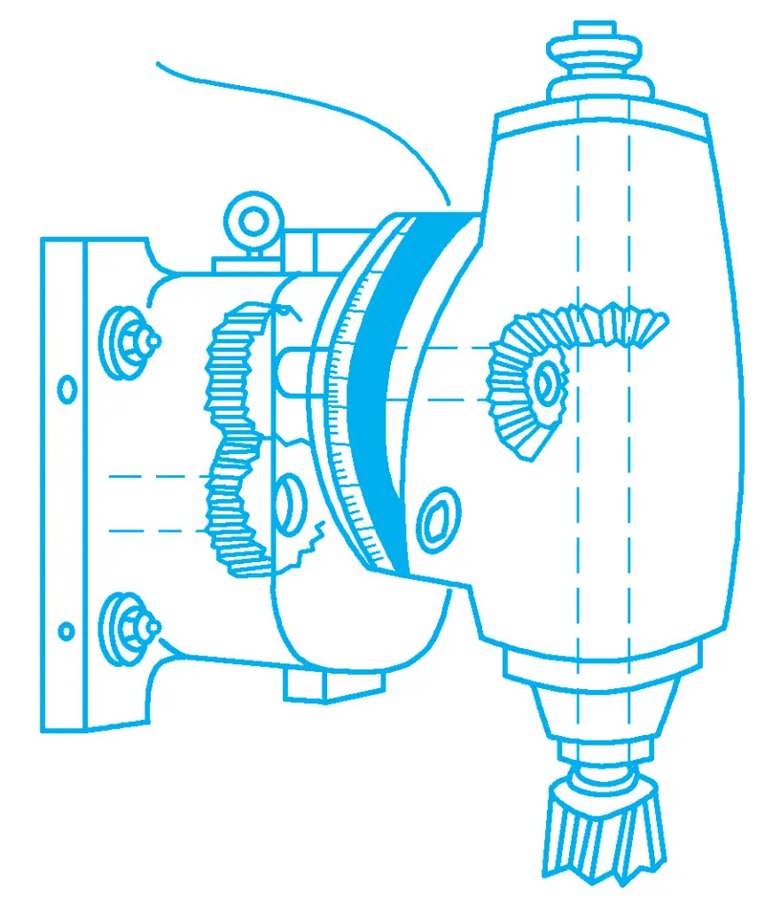
3. Universal milling head
The universal milling head (see Figure 12) is also used on horizontal milling machines, and it can rotate 360° in two mutually perpendicular planes. Therefore, it can make the milling head spindle form any angle with the worktable surface, realizing the milling processing of various surfaces with angle requirements in one clamping. The transmission ratio between its spindle and the milling machine spindle is also 1:1.
IV. Milling Cutter
1. Types of milling cutters
Milling cutters are a type of multi-tooth cutting tool, with a wide variety, and can be classified according to their use as follows.
(1) Milling cutters for machining planes
1) Cylindrical milling cutter
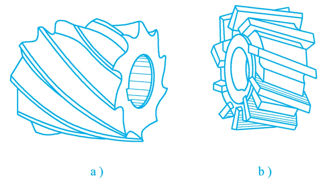
It can be used to machine relatively narrow planes on horizontal milling machines. The cylindrical milling cutter can be made entirely of high-speed tool steel (see Figure 13a), or it can be manufactured with cemented carbide inserts (see Figure 13b).
a) Integral type
b) Insert type
To improve the stability during milling, spiral-shaped teeth are common. This milling cutter has two types: the coarse-tooth cylindrical milling cutter has fewer teeth, high tooth strength, large chip space, and more regrinding times, suitable for rough machining; the fine-tooth cylindrical milling cutter has more teeth and operates smoothly, suitable for finishing.
When selecting the diameter of the milling cutter, it should ensure that the milling cutter spindle has sufficient rigidity and strength, usually based on the milling amount and the milling cutter spindle to select the diameter of the milling cutter.
2) Face milling cutter
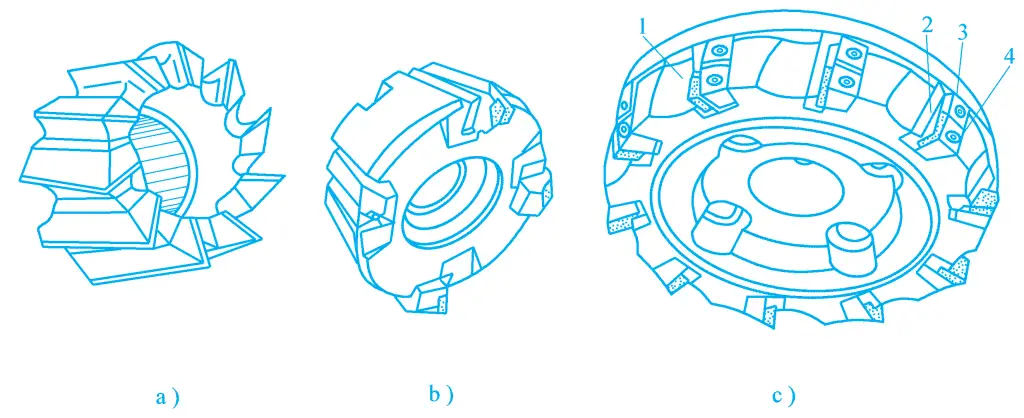
Small diameter face milling cutters are made entirely of high-speed tool steel (see Figure 14a), large diameter face milling cutters are assembled with welded cemented carbide cutter heads (see Figure 14b), or use mechanically clamped indexable cemented carbide inserts (see Figure 14c). Cemented carbide face milling cutters are suitable for high-speed milling of planes, because of their good rigidity, high efficiency, and good machining quality, thus they are widely used.
a) Integral cutter blade
b) Welded cemented carbide cutter blade
c) Mechanically clamped indexable cemented carbide cutter blade
1—Cutter body
2—Positioning seat
3—Positioning seat clamp
4—Cutter blade clamp
(2) Milling cutters for machining grooves
1) Three-edge milling cutter
In addition to the circumferential surface having the main cutting edge, the three-edge milling cutter also has secondary cutting edges on both side surfaces, thereby improving cutting performance, increasing cutting efficiency, and reducing the surface roughness of the workpiece. It is mainly used for machining grooves and step surfaces. The three-edge milling cutter can be divided into straight-tooth three-edge milling cutter, staggered-tooth three-edge milling cutter, and inserted-tooth three-edge milling cutter, as shown in Figure 15.
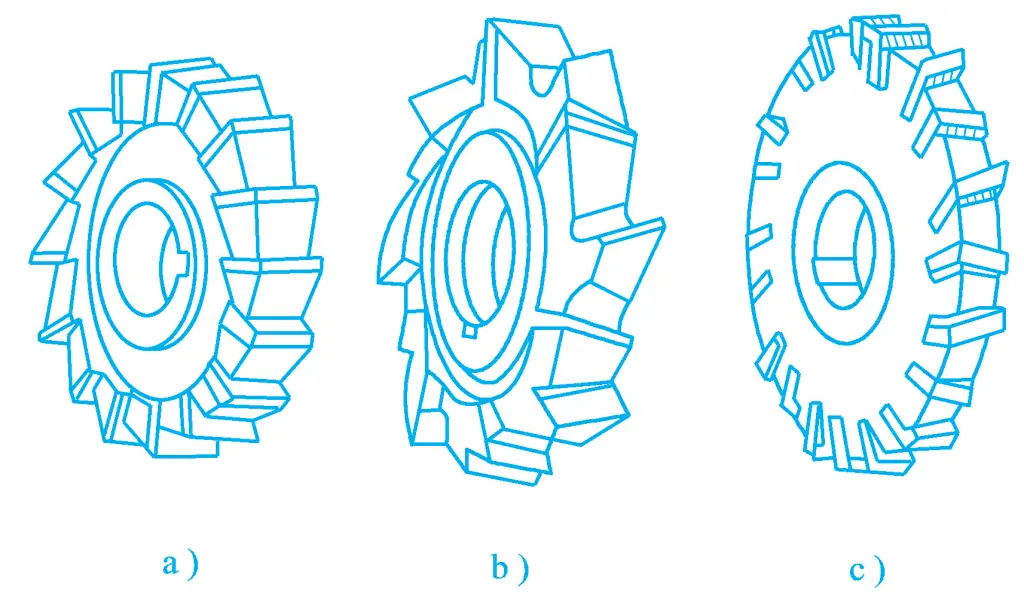
a) Straight-tooth three-edge milling cutter
b) Staggered-tooth three-edge milling cutter
c) Inserted-tooth three-edge milling cutter
2) Saw blade milling cutter
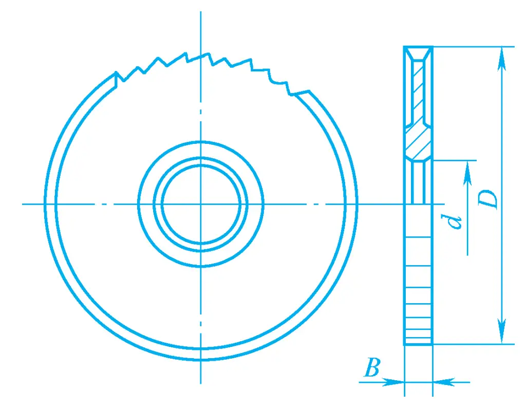
Figure 16 shows the saw blade milling cutter, mainly used for cutting off workpieces or milling narrow slots on workpieces. To avoid clamping the cutter during the milling process, the thickness of the blade decreases from the edge to the center.
3) Vertical milling cutter
Figure 17 shows the vertical milling cutter, similar to a small diameter cylindrical milling cutter with a handle, which can be used for machining grooves, as well as flat surfaces, step surfaces, and forming surfaces using a template.
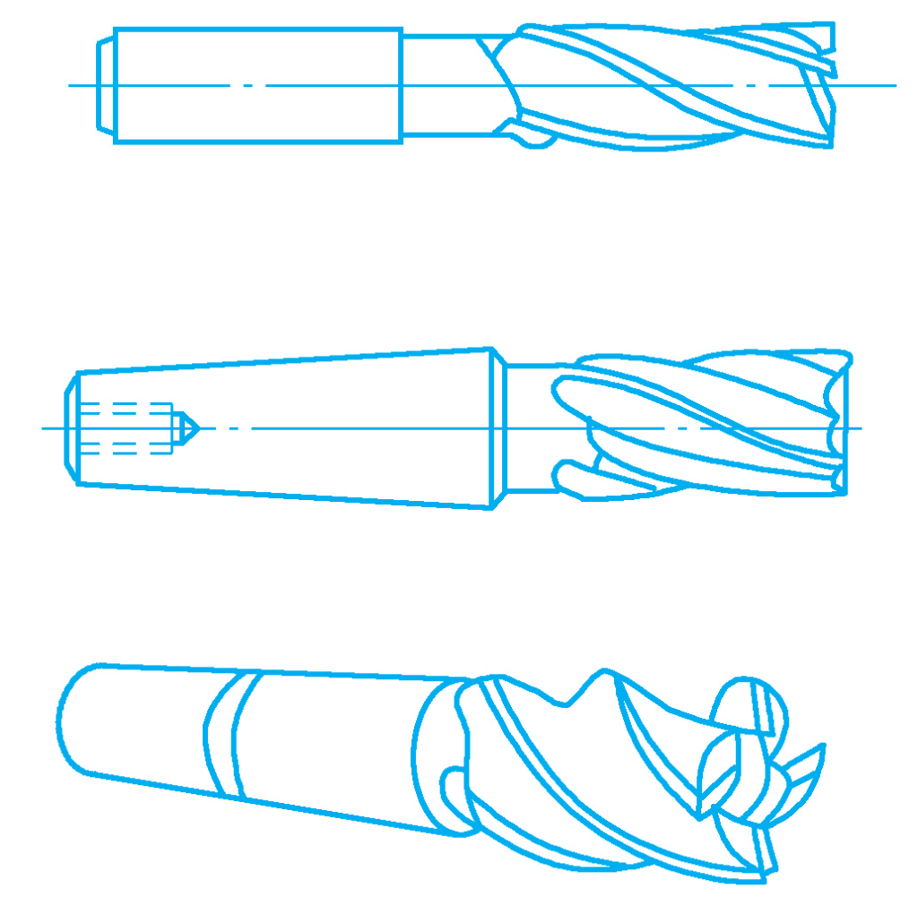
When the diameter of the vertical milling cutter is small, the shank is made straight; when the diameter is large, the shank is made tapered. The cutting edge on the cylindrical surface of the vertical milling cutter is the main cutting edge, and the cutting edge on the end face does not pass through the center, which is the secondary cutting edge. It is not suitable to make axial feed movement during work.
4) Keyway milling cutter
Figure 18 shows the keyway milling cutter, mainly used for machining keyways on shafts. The keyway milling cutter shown in Figure 18a has a shape similar to that of a vertical milling cutter, but it only has two teeth, and the end face cutting edge extends to the center, with the end face cutting edge being the main cutting edge and the circumferential cutting edge being the secondary cutting edge. Therefore, it can make an appropriate amount of axial feed when machining keyways that are not open at both ends. The keyway milling cutter shown in Figure 18b is specially used for machining semi-circular keyways on shafts.
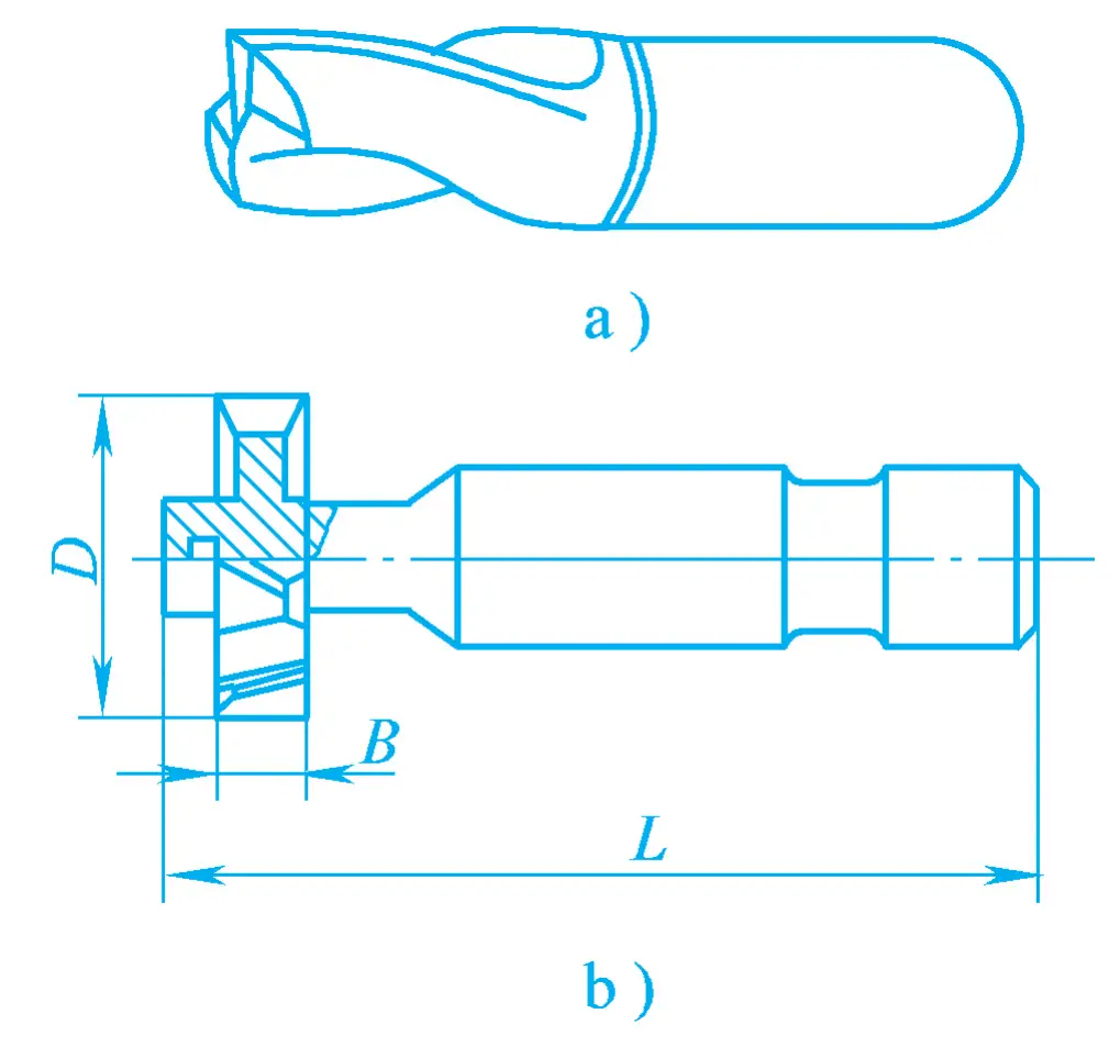
a) Keyway milling cutter
b) Semi-circular key milling cutter
5) Angle milling cutter
Figure 19 shows the angle milling cutter, mainly used for machining grooves and inclined surfaces with angles. The single angle milling cutter shown in Figure 19a has a conical cutting edge as the main cutting edge, and the end face cutting edge as the secondary cutting edge. The double angle milling cutter shown in Figure 19b has cutting edges on both conical surfaces as the main cutting edges. It includes symmetrical double angle milling cutters and asymmetrical double angle milling cutters.
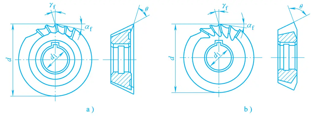
a) Single angle milling cutter
b) Double angle milling cutter
(3) Milling cutters for machining forming surfaces
1) Forming milling cutter
The forming milling cutter is a special tool used on milling machines for machining forming surfaces, and its cutting edge shape is designed according to the contour shape of the workpiece surface. It has high productivity and can ensure the interchangeability of workpiece shape and size, therefore it is widely used. Figure 20 shows several types of forming milling cutters.
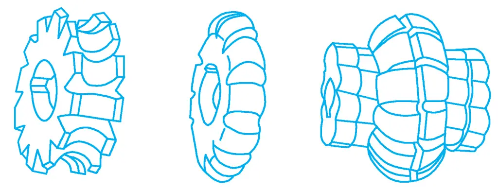
2) Mold milling cutter
Figure 21 shows the mold milling cutter, used for machining mold cavities or convex mold forming surfaces, widely applied in mold manufacturing. It evolved from the vertical milling cutter, mainly divided into conical vertical milling cutters, cylindrical ball nose vertical milling cutters, and conical ball nose vertical milling cutters. The type and size of the mold milling cutter are selected according to the shape and size of the workpiece.
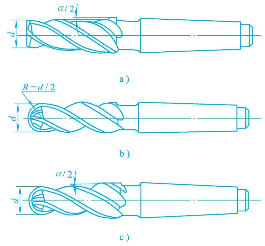
a) Conical vertical milling cutter
b) Cylindrical ball nose vertical milling cutter
c) Conical ball nose vertical milling cutter
Hard alloy mold milling cutters can replace diamond files and grinding heads for machining various molds with hardness less than 65HRC after quenching, and they have high cutting efficiency.
2. Installation of milling cutters
The installation method of milling cutters on the spindle varies according to the structure of the cutter body.
(1) Installation of hole milling cutters
1) Cutter shank
Hole-type milling cutters are generally mounted on the milling machine spindle using a cutter shank, which consists of a cutter shaft, washers, a locking key, a bushing, and a nut, as shown in Figure 22a.

The diameter size of the cutter shaft is designed and manufactured according to the inner hole of commonly used milling cutters, generally available in φ16mm, φ22mm, φ27mm, φ32mm, φ40mm, and φ50mm six types. Figure 22b shows a type of cutter shaft without a bushing, when using this type of cutter shaft, the neck of the cutter shaft is directly supported on the cutter shank bracket, while the previous type of cutter shank is supported on the cutter shank bracket through a bushing.
2) Drawbar
After the cutter shank is mounted on the spindle, it must be tightened with a drawbar before use, the shape and use of the drawbar are shown in Figure 23.
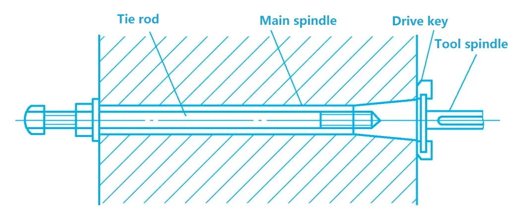
3) Milling cutter installation
First, insert the cutter shaft into the spindle hole, and tighten it with a drawbar. Several washers of appropriate length are installed at the inner end of the cutter shaft to determine the position of the milling cutter.
When installing the milling cutter, place a locking key between the milling cutter and the cutter shaft, then install washers and a bushing of appropriate length on the outside of the milling cutter, pull out the cantilever to the appropriate position, mount the cutter shank bracket on the cantilever and match it with the cutter shank bushing (when using the cutter shank shown in Figure 22b, the neck of the cutter shank is directly inserted into the support hole of the cutter shank bracket), and tighten the cantilever, cutter shank bracket fastening nut, and cutter shank nut.
(2) Installation of shank milling cutters
1) Taper shank milling cutter installation
The taper of taper shank milling cutters is generally Morse taper. If the taper of the milling cutter shank matches the taper of the spindle hole, it can be directly installed in the spindle hole. If the taper of the milling cutter shank does not match the taper of the spindle hole, it cannot be directly installed in the spindle hole, and must be installed using an intermediate sleeve transition, then tightened with a drawbar, the installation and removal process is shown in Figures 24a and b.
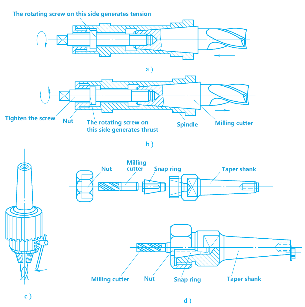
a) Tighten the milling cutter
b) Dismantle the milling cutter
c) Install straight shank milling cutter with drill chuck
d) Install straight shank milling cutter with spring collet
2) Installation of straight shank milling cutters
When the milling cutter has a straight shank, it is to be installed using a drill chuck or a spring collet, as shown in Figures 24c and d.
(3) Installation of carbide face milling cutters
The holding part of carbide face milling cutters can be divided into two types: one is with a shank structure, and the other is a sleeve type structure. Small diameter face milling cutters are generally made with a shank structure, the taper shank matches with the spindle taper hole for positioning and torque transmission. The threaded hole at the end of the shank is used to tighten the milling cutter, and its installation method is similar to that of vertical milling cutters.
Large diameter face milling cutters are all made into a sleeve structure, and their centering and installation methods with the spindle have three types: Figure 25a shows a stop made on the end face of the cutter body matching with the front end of the milling machine spindle; Figure 25b shows the use of a center shaft installed in the spindle taper hole matching with the inner hole of the cutter body for centering; Figure 25c shows the use of an assembly ring structure for tool centering. After the tool is positioned on the spindle, it is fastened to the spindle with screws.

V. Milling machining methods
1. Milling methods
Adopting appropriate milling methods can reduce vibration, stabilize the milling process, and improve the surface quality of the workpiece, the life of the milling cutter, and the productivity of milling.
(1) End milling and peripheral milling
Compared with peripheral milling, end milling is more likely to achieve a smaller surface roughness value and higher labor productivity. This is because more teeth are involved in milling during end milling, resulting in smaller changes in cutting force, making the milling more stable. Additionally, the secondary cutting edge and chamfering tip have a polishing effect, while in peripheral milling, only the main cutting edge works.
Moreover, during end milling, the spindle has good rigidity, and it is easy to use carbide indexable inserts, thus allowing for larger cutting parameters and higher productivity. In plane milling, end milling has basically replaced peripheral milling, but peripheral milling can process shaped surfaces and composite surfaces.
(2) Climb milling and conventional milling
There are two ways of circular milling: climb milling and conventional milling.
1) Conventional milling
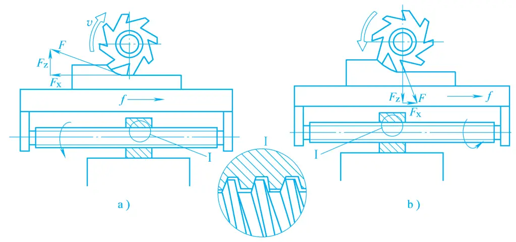
As shown in Figure 26a, during milling, the direction of the cutting speed when the milling cutter enters the workpiece is opposite to the direction of the feed motion of the workpiece, which is called conventional milling.
a) Conventional milling
b) Climb milling
In conventional milling, the cutting thickness gradually increases from zero to the maximum value. At the beginning of the cut, due to the influence of the blunt radius of the cutting edge, the tooth slips on the surface of the workpiece, producing squeezing and friction, until after a certain extent of sliding, the tooth can cut into the metal layer. This makes the tooth prone to wear, and the workpiece surface produces a severe cold-hardened layer.
The next tooth repeats the process of sliding, squeezing, and friction on the cold-hardened layer produced by the previous tooth, exacerbating tooth wear and increasing the surface roughness of the workpiece. Additionally, when the tooth begins to cut into the workpiece, the vertical milling component force Fz is downward, and when the milling cutter turns a certain angle later, the vertical milling component force Fz is upward, which can easily cause vibration and has a tendency to lift the workpiece, requiring a larger clamping force.
In conventional milling, the longitudinal milling component force Fx is opposite to the feed direction, keeping the screw and nut contact surfaces always tight, so the worktable does not experience creeping, making the milling process more stable. Therefore, in production, when the milling machine does not have a gap adjustment mechanism, conventional milling is generally used.
2) Climb milling
As shown in Figure 26b, during milling, the direction of the cutting speed when the milling cutter exits the workpiece is the same as the feed motion direction of the workpiece, which is called climb milling. In climb milling, the cutting thickness gradually decreases from the maximum to zero, without the slipping phenomenon of the tooth in conventional milling, greatly reducing the hardening degree of the machining, resulting in higher processed surface quality and longer tool life.
As can be seen from Figure 26b, in climb milling, the cutting force acting on the tooth at different positions is also unequal. However, at any instant, the vertical milling component force Fz always presses the workpiece towards the worktable, avoiding up and down vibration, making the milling relatively stable.
On the other hand, although the size of the longitudinal milling component force Fx varies at different instants, its direction is always the same as the feed direction. Due to the gap between the screw and nut driving the worktable, when the longitudinal component force F x exceeds the friction force of the guide rail pair below the worktable, the milling cutter will cause the worktable to drive the screw to move to the right, causing the worktable to vibrate.
Due to the constant change in cutting force, the worktable moves back and forth longitudinally within the gap range of the screw and nut, and the feed is uneven, which in severe cases can cause the milling cutter to chip. Therefore, if using climb milling, it is necessary to have a mechanism to eliminate lateral clearance in the feed screw nut pair of the milling machine worktable, or take other effective measures.
The X6132 universal milling machine is equipped with a climb milling clearance elimination mechanism, which can eliminate the lateral clearance in the feed screw nut pair of the worktable, solving the problem of the worktable moving left and right during climb milling. The motion of the worktable of CNC milling machines mostly uses other gapless transmission methods such as ball screws, so there is no need to consider the issue of clearance.
(3) Symmetrical end milling and asymmetrical end milling
In end milling, according to the different relative positions of the milling cutter and the workpiece, it can be divided into symmetrical end milling, asymmetrical conventional milling, and asymmetrical climb milling, as shown in Figure 27.

a) Symmetrical end milling
b) Asymmetrical conventional milling
c) Asymmetrical climb milling
1) Symmetrical end milling
During the milling process, the axis of the face milling cutter is always located at the symmetrical center of the milling arc length, with the upper part of climb milling equal to the lower part of conventional milling. This milling method is called symmetrical end milling, as shown in Figure 27a.
When using this method, since the diameter of the milling cutter is larger than the milling width, the cutting thickness when the tooth enters and exits the workpiece is greater than zero, thus avoiding the next tooth cutting on the cold-hardened layer cut by the previous tooth. Generally, this milling method is often used in end milling, especially suitable for milling hardened steel.
2) Asymmetrical conventional milling
When the axis of the face milling cutter is offset to one side of the symmetrical center of the milling arc length, and the climb milling part is larger than the conventional milling part, this milling method is called asymmetric climb milling, as shown in Figure 27b. The characteristic of this milling method is that the cutter teeth cut in with a smaller cutting thickness and cut out with a larger cutting thickness.
In this way, the impact of cutting in is smaller, suitable for end milling of non-alloy steel and high-strength low-alloy steel, this cutting method can increase the tool life by more than twice compared to symmetric milling. In addition, due to the larger contact angle of the cutter teeth and more teeth participating in the cutting at the same time, the change in cutting force is small, the cutting process is more stable, and the roughness value of the machined surface is smaller.
3) Asymmetric conventional milling
When the axis of the face milling cutter is offset to one side of the symmetrical center of the milling arc length, and the conventional milling part is larger than the climb milling part, this milling method is called asymmetric conventional milling, as shown in Figure 27c. The characteristic of this milling method is that the cutter teeth cut in with a larger cutting thickness and cut out with a smaller cutting thickness.
It is suitable for machining materials such as stainless steel with medium strength and high elasticity and plasticity. This can reduce the sliding, squeezing phenomenon of the cutter teeth during climb milling and the cold hardening degree of the machined surface, which is beneficial to improve the tool life. Under other constant conditions, as long as the offset distance is selected appropriately, the tool life can be doubled compared to symmetric end milling.
2. Milling methods for typical surfaces
(1) Milling flat surfaces
Milling flat surfaces can be done on a horizontal milling machine or on a vertical milling machine, using face milling cutters, cylindrical milling cutters, or even end milling cutters, etc. Figures 28a and b show milling flat surfaces with a face milling cutter on a horizontal milling machine and a vertical milling machine.
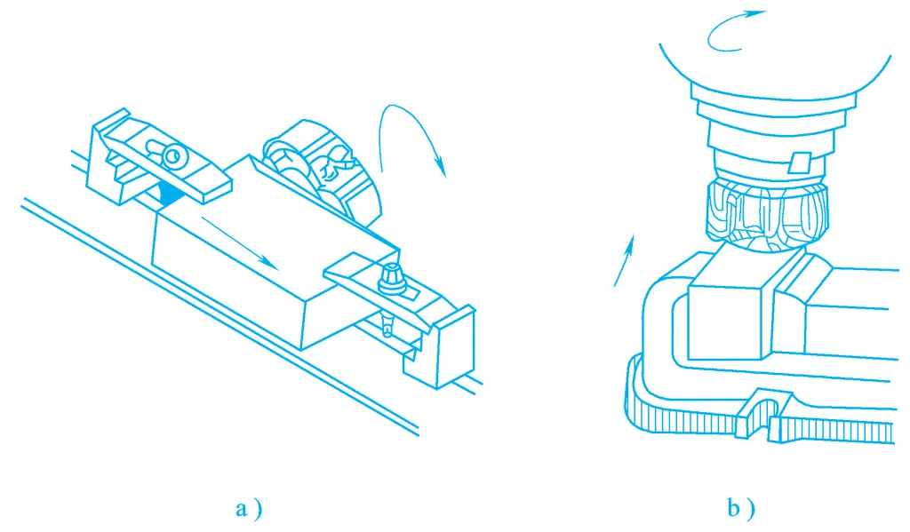
a) Milling flat surfaces on a horizontal milling machine
b) Milling flat surfaces on a vertical milling machine
(2) Milling beveled surfaces
Milling beveled surfaces is essentially milling flat surfaces, but it requires tilting the workpiece or milling cutter at an angle, or using an angled milling cutter.
1) Tilting the workpiece to mill beveled surfaces
Mainly includes milling beveled surfaces according to lines and using a vise for milling beveled surfaces, in addition, a universal rotary table, tilting wedges, special fixtures, etc., can also be used for milling beveled surfaces.
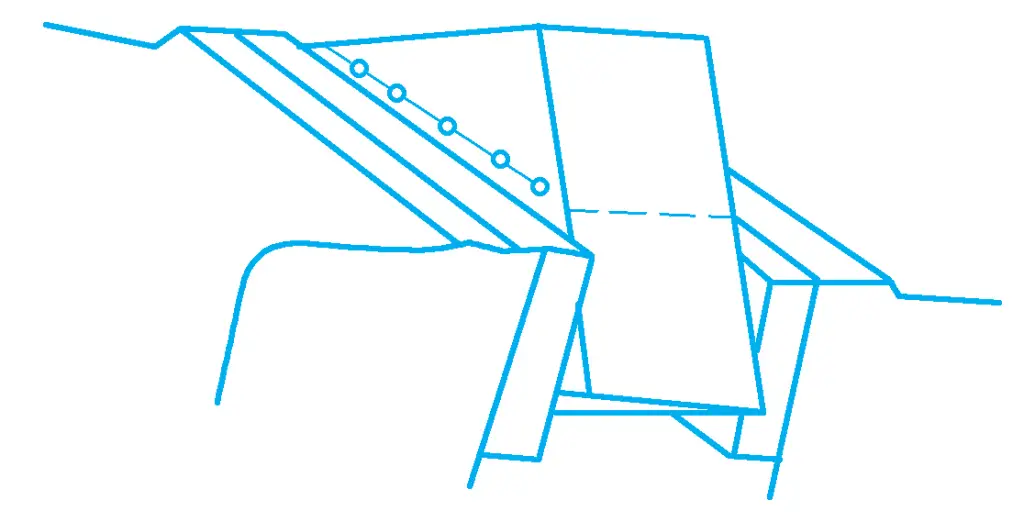
- Milling beveled surfaces according to lines, the workpiece after drawing lines can be clamped with a vise for milling beveled surfaces, as shown in Figure 29.
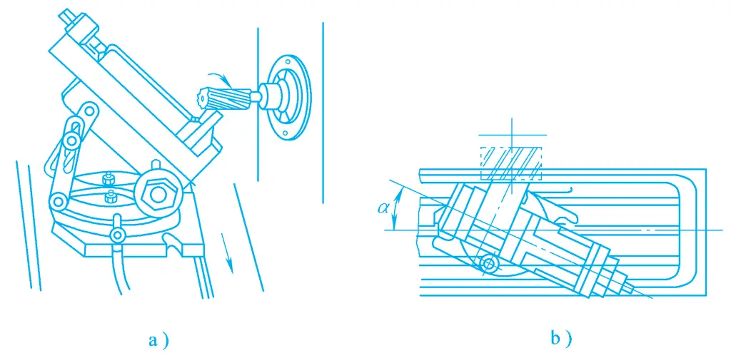
- Using a vise to mill beveled surfaces, Figure 30a shows the method of milling beveled surfaces with a workpiece mounted on a universal vise, and Figure 30b shows the method of milling beveled surfaces with a common rotatable vise on a horizontal milling machine.
2) Tilting the milling cutter to mill beveled surfaces
Mainly includes milling beveled surfaces with a face milling cutter and milling beveled surfaces with the cylindrical cutting edge of an end milling cutter.
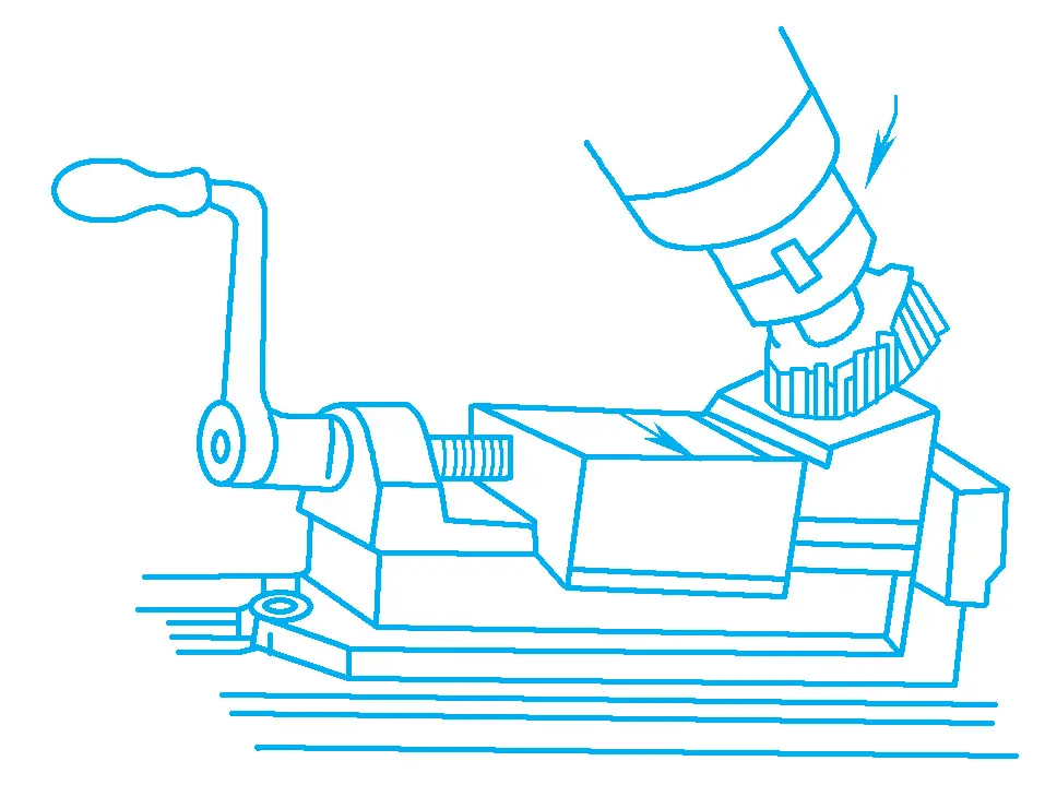
Milling beveled surfaces with a face milling cutter. As shown in Figure 31, after mounting the face milling cutter on the spindle of the vertical milling head, if the spindle of the vertical milling head is tilted at an angle, then the face milling cutter will also tilt at the same angle to mill the beveled surface. The size of the tilting angle depends on the machined surface of the workpiece.
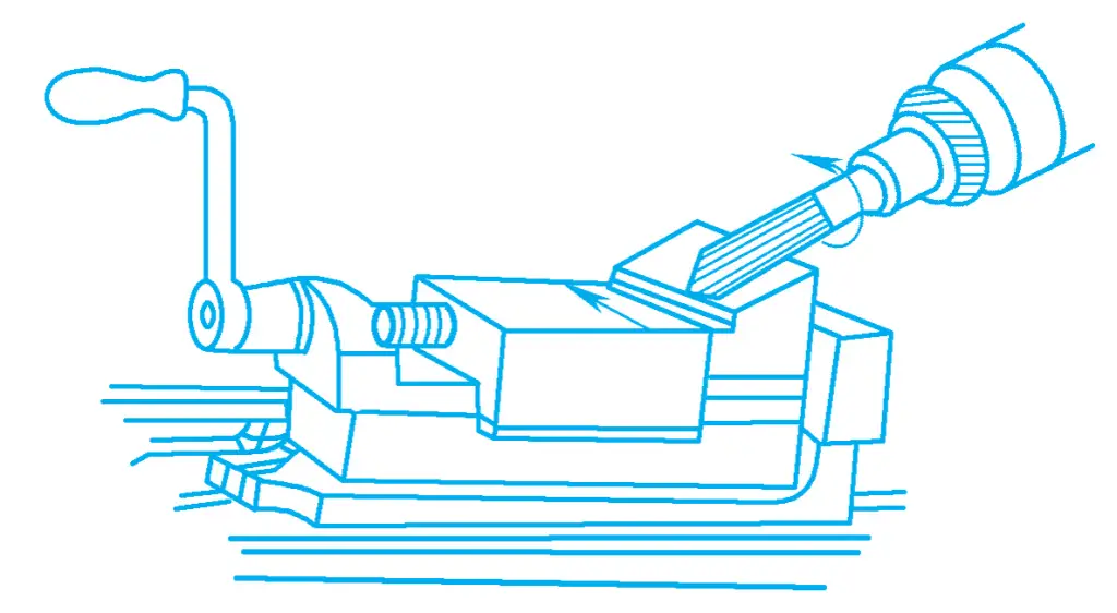
Milling beveled surfaces with the cylindrical cutting edge of an end milling cutter. When the vertical milling head does not rotate, if the reference surface of the workpiece is parallel to the worktable surface, the flat surface milled with the cylindrical cutting edge of the end milling cutter is perpendicular to the worktable surface. If the vertical milling head is rotated at a certain angle, then beveled surfaces can be milled, as shown in Figure 32.
3) Milling beveled surfaces with an angle milling cutter
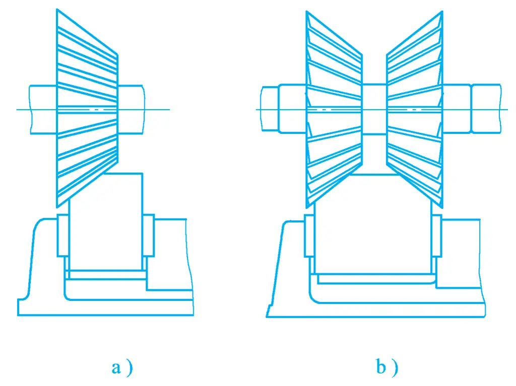
Figure 33a shows the working situation of milling beveled surfaces with a single angle milling cutter. Angle milling cutters are only suitable for milling standard angle (30°, 45°, 60°, etc.) beveled surfaces and narrow beveled surfaces. When there are two beveled surfaces on the workpiece, two angle milling cutters can be combined to mill, to improve productivity, as shown in Figure 33b.
(3) Milling steps and grooves
1) Milling of steps
Figure 34 shows the milling of steps on a horizontal milling machine, where steps of small size can be milled with a three-face cutter, and larger ones with a combination cutter. The milling of steps can also be done on a vertical milling machine, where larger diameter end mills are often used.
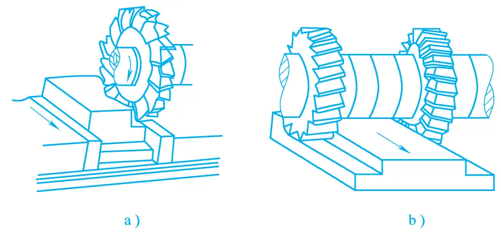
a) Milling steps with a three-face cutter
b) Milling steps with a combination cutter
2) Milling of right-angle grooves and keyways
Right-angle grooves are divided into through grooves, closed, and semi-closed types. Right-angle through grooves are mainly milled with a three-face cutter on a horizontal milling machine, but can also be milled with an end mill on a vertical milling machine. Closed and semi-closed grooves can only be milled with keyway cutters and end mills, as shown in Figure 35.
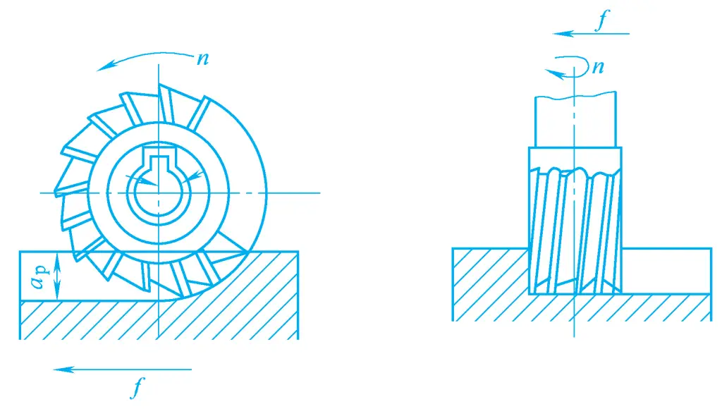
Grooves for keys installed on various transmission shafts are called keyways, which can be divided into flat keyways and semi-circular keyways according to the shape of the groove bottom. Milling flat keyways is essentially milling right-angle grooves on the shaft.
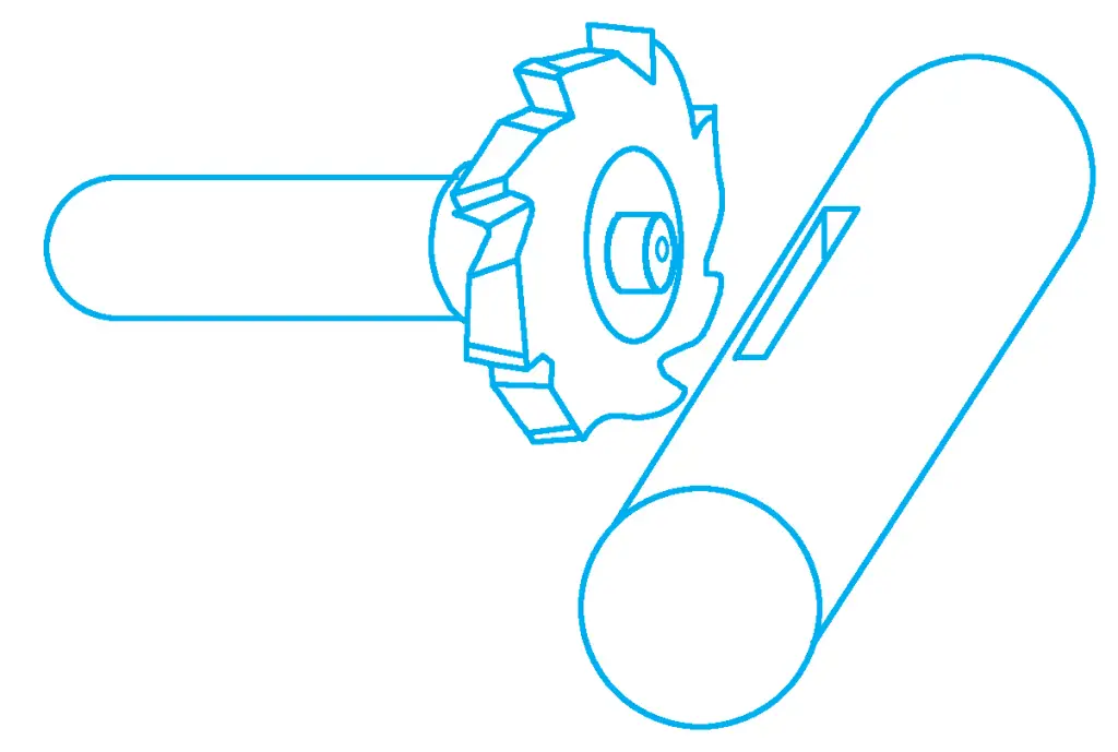
When milling keyways, the cutter should be selected according to the shape of the keyway. Circular head keyways that are closed or semi-closed at both ends of the shaft are mainly processed with a keyway cutter on a vertical milling machine or keyway milling machine. For through grooves, a three-face cutter is mostly used on a horizontal milling machine, while semi-circular keyways are mainly milled with a semi-circular keyway cutter on a horizontal milling machine.
When machining on a horizontal milling machine, the cutter is above the workpiece, which is convenient for the operator to visually inspect. Additionally, a center can be installed on the cutter bar support to press against the center hole at the front end of the semi-circular key cutter, increasing the rigidity of the cutter, as shown in Figure 36.
3) Milling of special-shaped grooves
In mechanical manufacturing, some parts have grooves of special shapes, such as milling T-slots on a milling machine. The milling steps are shown in Figure 37, starting with milling a right-angle through groove on a vertical milling machine (or with a three-face cutter on a horizontal milling machine), then milling the T-slot with a T-slot cutter on a vertical milling machine, and finally using a chamfering cutter for chamfering.
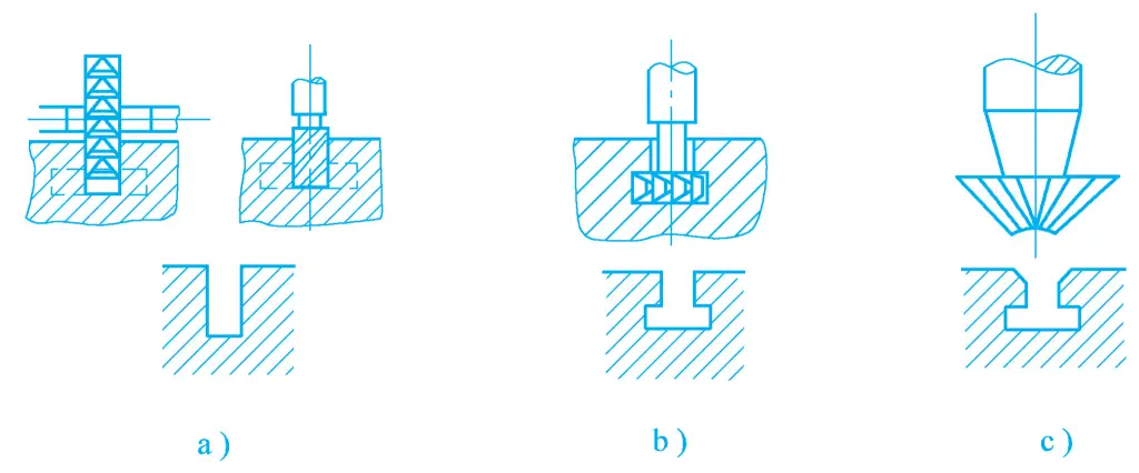
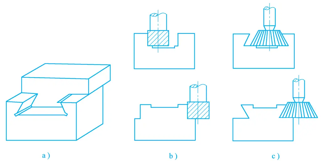
Figure 38 shows the machining method and steps for parts with dovetail slots and dovetail blocks, which are basically the same as machining T-slots. The first step is to mill a right-angle slot with an end mill or face mill (see Figure 38b), and the second step is to mill the dovetail slot or dovetail block with a dovetail slot cutter (see Figure 38c).
