Essential Guide to Common Metal Types and Uses
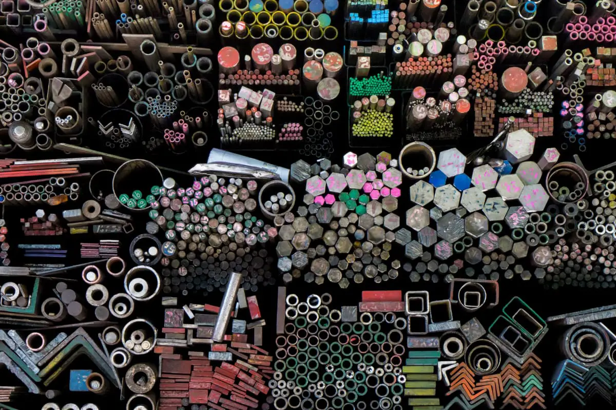
I. Non-alloy Steel Non-alloy steel refers to an iron-carbon alloy with wc <2.11%, containing small amounts of impurities such as Si,…
The main functions of the relief valve are two: one is to maintain a constant outlet pressure of the hydraulic pump in the throttle adjustment system of the quantitative pump, and to overflow the excess oil of the hydraulic pump back to the tank. At this time, the relief valve acts as a pressure relief valve; the second is to act as a safety device in the system.
According to the different structures, relief valves can be divided into direct-acting type and pilot-operated type.
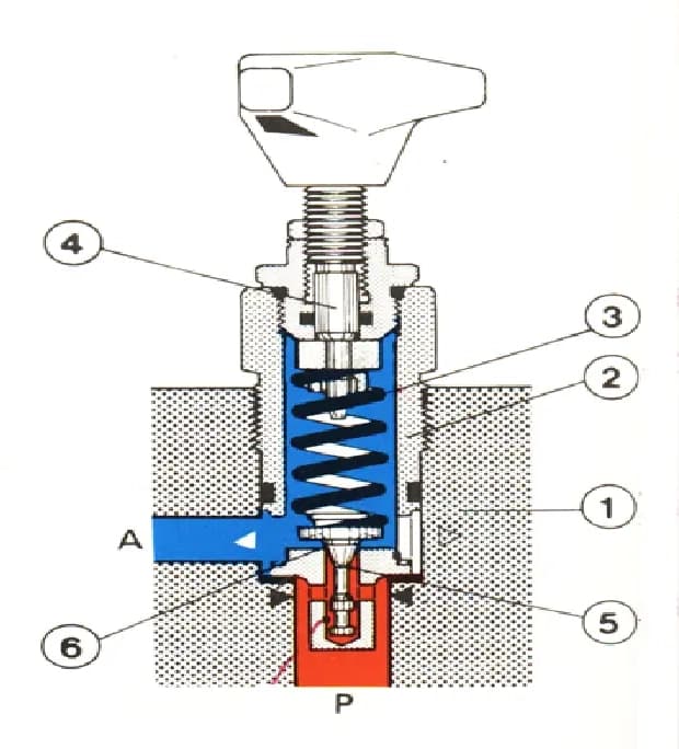
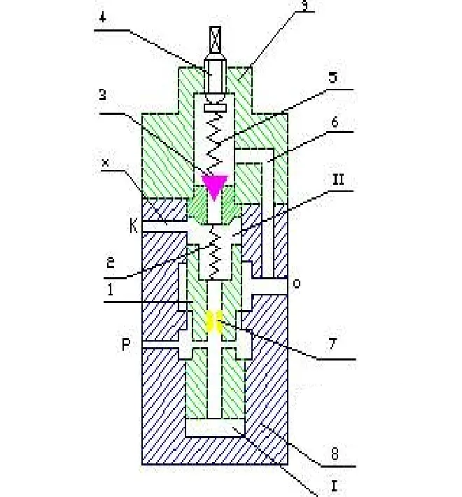
Direct-acting relief valves can be divided into ball valve type, cone valve type, slide valve type, etc., according to the form of their spools. Now, take the Rexroth DBD direct-acting relief valve as an example to explain the structure and working principle of the direct-acting relief valve. Its structure is as follows.
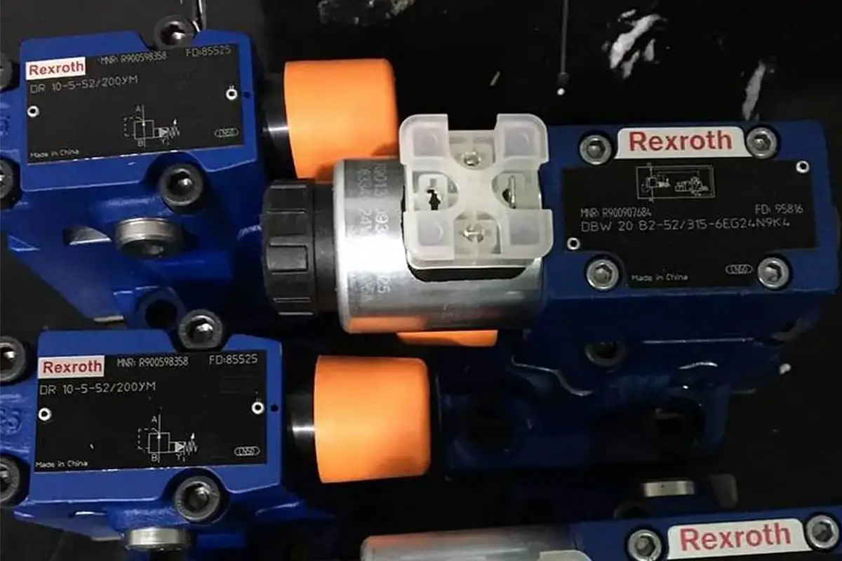
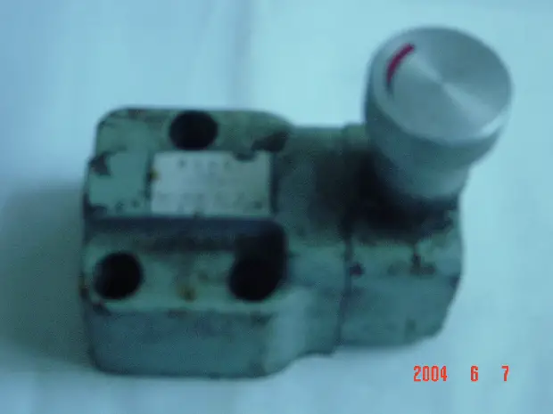
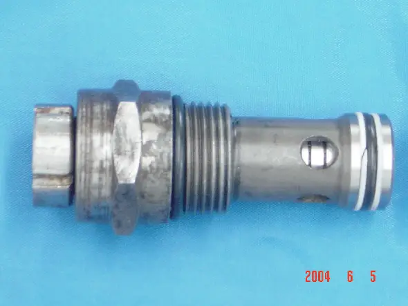
The following 2 pictures are the physical objects of the relief valve.
The opening pressure of the relief valve is P
Pk ·A=PR =KX0 , or Pk =KX0 /A
When the spool is in a certain position, the force balance of the spool is:
P·A=K(X0 +x)
In the formula, x is the additional compression amount of the spring.
It can be seen from the above formula that when the spool is in different positions, the overflow pressure changes. However, since the additional compression amount x of the spring is relatively small compared to the pre-compression amount X 0 , it can be considered that the overflow pressure P remains essentially constant. This is the working principle of the relief valve acting as a pressure relief valve.
The direct-acting relief valve controls the overflow pressure by directly balancing the spring force on the upper end of the spool with the hydraulic pressure on the lower end. Generally, direct-acting valves are only made as low-pressure, low-flow overflow valves.
The pilot-operated relief valve consists of a main valve and a pilot valve. The structural principle of the pilot valve is the same as that of the direct-acting relief valve, but generally adopts a conical seat valve structure. The main valve can be divided into: spool type (single-stage concentric) structure, two-stage concentric structure, and three-stage concentric structure. The figure below shows the working principle diagram of a single-stage concentric relief valve.
Now let’s study the state when the main valve spool is in a certain equilibrium position. Ignoring the weight of the spool and friction, the force balance of the main valve is:
PA=P 1 A+F a =P 1 A+K(x 0 +x) or P=P 1 +K(x 0 +x)/A
From the above equation, it is known that the pressure controlled by the pilot-operated relief valve consists of P 1 and F a /A. Due to the presence of the main valve chamber P 1 . Even if the controlled pressure P is high, the force of the balance spring on the main valve only needs to be small, as long as it can overcome the friction to reset the main spool.
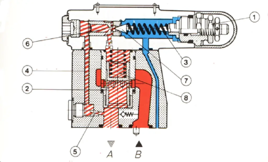
The figure below shows the structural principle diagram of a two-stage concentric high-pressure relief valve. The valve consists of a pilot valve and a main valve. The guide surface and conical surface of its main spool fit well with the valve sleeve, and the concentricity requirements at both places are high, hence the name two-stage concentric.
When the system pressure is below the set value of the pressure regulating spring, the main spool is pressed down on the valve seat, and the inlet and overflow ports are not connected. When the system pressure exceeds the set value of the pressure regulating spring, the pilot valve opens, and the oil returns to the oil chamber.
In this way, the main spool is lifted up, connecting the P chamber and the 0 chamber, allowing the pressure oil to overflow from the P chamber to the 0 chamber. The damping hole damps the movement of the spool to improve the stability of the relief valve’s operation. This type of valve has good sealing, high oil throughput capacity, low pressure loss, and compact structure.
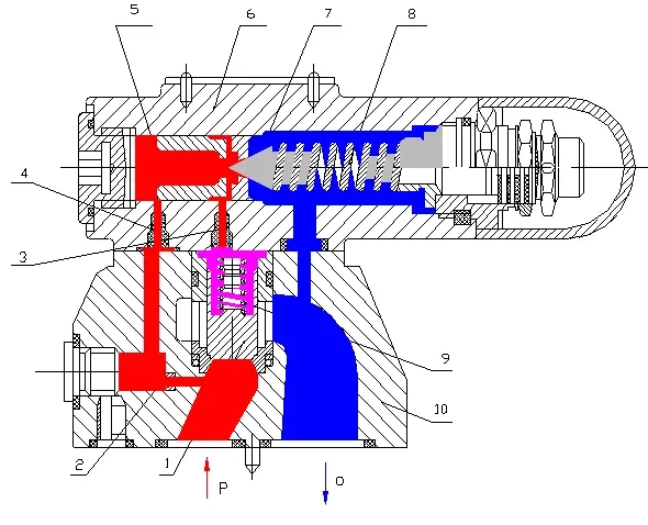
1 – Main Valve Spool
2, 3, 4 – Throttle Orifice
5 – Pilot Valve Seat
6 – Pilot Valve Body
7 – Pilot Valve Spool
8 – Pressure Adjustment Spring
9 – Soft Spring
10 – Valve Body
When the overflow volume changes, the valve opening degree also changes accordingly, and the overflow pressure changes as well. This is the pressure-flow characteristic of the relief valve. The figure below shows two working positions of a direct-acting relief valve. Figure a is the closed state, and figure b is the open state.
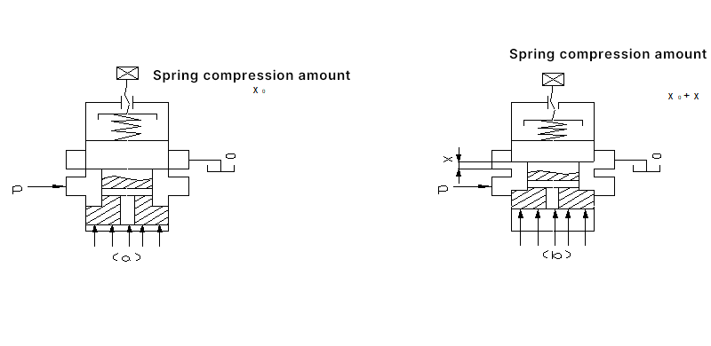
When the system pressure Pk is such, the hydraulic pressure balances with the spring preload, and the valve is in a critical state of just opening. At this time, the force balance equation of the spool is:
Pk.πd2/4=KX0
where
When the oil pressure increases to P, the valve opening is x, and the force balance equation of the valve core is: P k . πd 2 /4=K(x 0 +x)
Subtracting the two equations yields x= (πd 2 /4K)(p-p k )
The flow through the valve port can be calculated using the thin-walled orifice flow formula:
That is Q=Cq.a.(2/ρ)1/2p=Cq. πdx(2/ρ)1/2p
Rearranging the two equations yields: Q=(Cq π2d3/4K)(2/ρ)1/2(p3/2-pk.p1/2)
The above equation is the pressure-flow characteristic equation of the relief valve, and the corresponding characteristic curve is shown in the figure below.
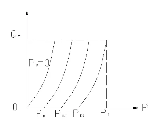
The following conclusions can be drawn from the above equation:
1) Different opening pressures p k correspond to different curves.
The size of P k can be adjusted by changing the pre-compression amount x 0 of the spring;
2) When the opening pressure p k is constant, the overflow pressure increases with the increase of overflow volume.
When the overflow volume reaches the rated flow QT of the valve, the corresponding pressure value is called the full flow overflow pressure PT of the overflow valve. It can be seen from the above formula that the smaller the spring stiffness K, the steeper the curve, the smaller the pressure change caused by the change of overflow volume, and the better the constant pressure performance.
Conversely, the pressure regulation performance is poor. The pressure regulation deviation (P k – P k ) and the opening ratio P k /PT are commonly used to measure the quality of constant pressure performance. The smaller the pressure regulation deviation, the better the constant pressure performance of the valve. And further, the opening ratio is used to measure the quality of constant pressure performance, the higher its value, the better.
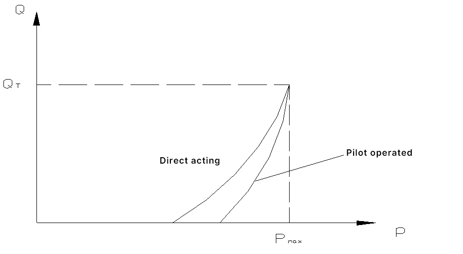
The constant pressure performance of overflow valves varies with their structure. The curves of direct-acting and pilot-operated relief valves with the same set pressure are drawn below for comparison. It can be seen from the figure that the constant pressure performance of pilot-operated relief valves is better than that of direct-acting relief valves.
The above analysis ignores the impact of frictional force when the valve spool moves. If frictional force is considered, the force balance equation for the spool when the valve closes to open is:
P’k. πd2/4=KX0+Ff
Therefore
P’k=4(KX0+Ff)/ πd2
And when the valve goes from open to closed, the force balance equation for the spool is
P“k.πd2/4=KX0-Ff
That is
P”k=4(KX0-Ff)/πd2
From the above two equations, it can be seen that due to the presence of frictional resistance, the opening pressure and closing pressure of the overflow valve are not equal.
The closing pressure is lower than the opening pressure, and the pressure-flow curve during the opening process does not coincide with that of the closing process, as shown in the figure below.
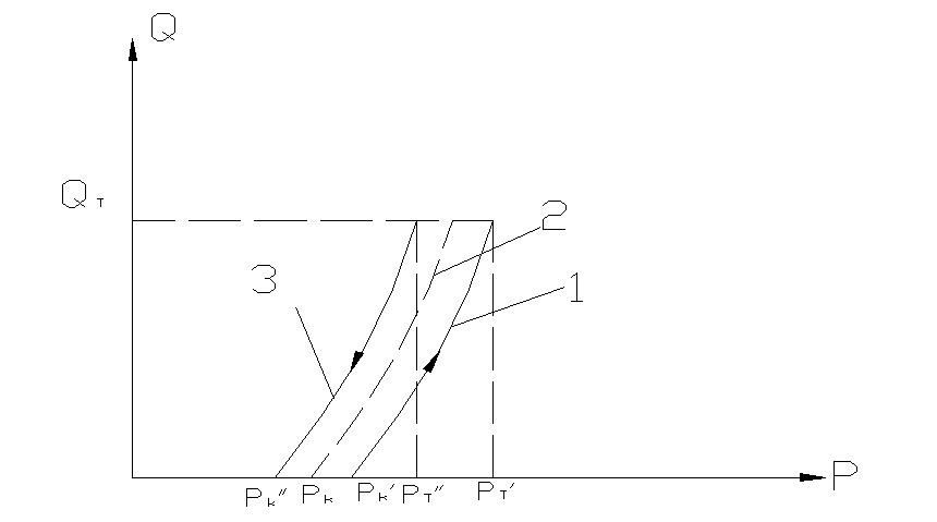
The dashed line 2 in the figure represents the ideal curve without friction resistance. Due to the need to overcome the friction resistance F f , the actual pressure loss must be greater than P k and rise to P’ k before the valve opens. When the overflow increases, the pressure rises along curve 1. When the overflow is Q T , the pressure is P’ T . Similarly, the pressure must decrease to P” T for it to drop along curve 3. When fully closed, the pressure is P” k .
There are two meanings to the working pressure stability of a relief valve. One refers to the variation in the adjusted pressure when the valve’s adjustment device remains unchanged. The other meaning refers to the fluctuation or oscillation of the system pressure when the relief valve is working, which is related to the flow pulsation of the pump source and the dynamic characteristics of the valve and pipeline, representing a comprehensive indicator.
When the pressure regulating spring is fully relaxed and the valve passes the rated flow, the difference between the inlet chamber pressure and the return chamber pressure is the valve’s pressure loss. It is mainly related to the damping in the main oil path of the valve, but when testing the pressure loss of the pilot-operated relief valve, it is also affected by the preload force of the balance spring.
For the pilot-operated relief valve, when its remote control port is directly connected to the oil tank and the valve passes the rated flow, the difference between the inlet chamber pressure and the return chamber pressure is called the unloading pressure. Obviously, it is related to the channel resistance and the preload force of the balance spring.
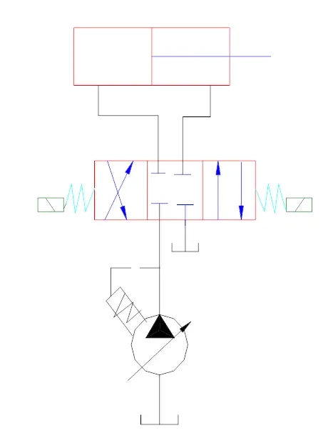
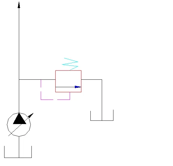
In the use of quantitative pump throttle speed regulation, adjusting the opening size of the throttle valve can regulate the flow into the actuator, and the excess oil from the quantitative pump flows back to the tank through the overflow valve. During the working process, the valve is always open, and the working pressure of the hydraulic pump is determined by the adjustment pressure of the overflow valve and is basically constant. See the figure below.
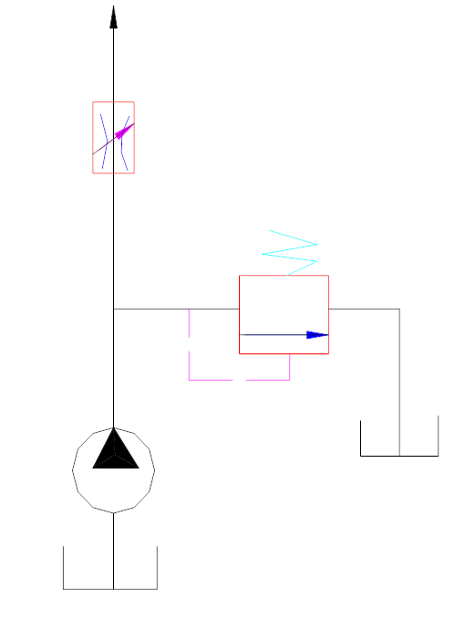
At this time, the valve is normally closed. Only when the system pressure exceeds the adjustment pressure of the overflow valve, the valve opens, and the oil flows back to the tank through the valve, so the system pressure does not increase further, thus preventing system overload and serving as a safety function. See the figure below.
By installing the overflow valve in the return oil path, adjusting the pressure spring of the overflow valve can regulate the size of the back pressure. See the figure below.
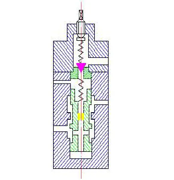
Connecting the remote control port K of the pilot-operated relief valve to the inlet of the remote pressure adjustment valve, and the outlet of the remote pressure adjustment valve to the tank, thus forming a remote pressure adjustment circuit. See the right figure. The structure of the remote pressure adjustment valve is shown in the left figure, which is similar to the pilot valve in the relief valve. Adjusting the pressure spring of the remote pressure adjustment valve can achieve remote pressure adjustment.
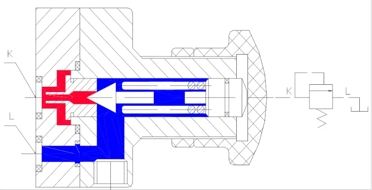
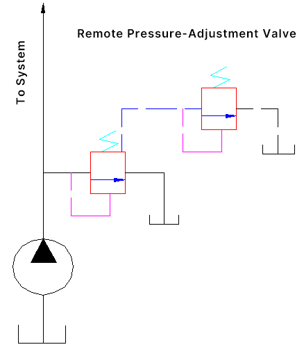
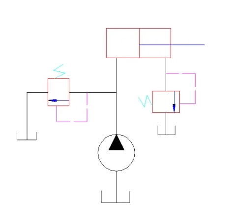
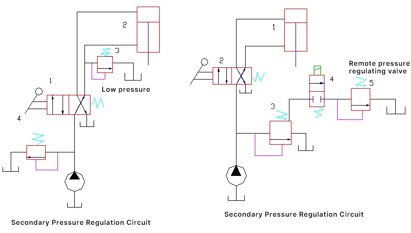
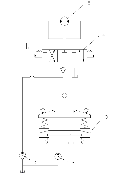
Figure 7-15 is an example of a two-stage pressure adjustment circuit. The piston descends for the working stroke, and the high-pressure relief valve 4 limits the system’s maximum pressure. The piston ascends for the non-working stroke, and the adjustment pressure of the low-pressure relief valve 3 only needs to overcome the self-weight of the moving parts and friction resistance. This circuit is commonly used in the hydraulic system of presses.
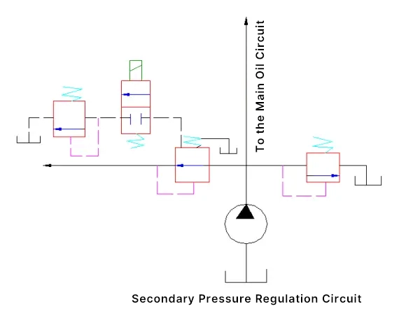
Figure 7-16 is another example of a two-stage pressure adjustment circuit. The descending pressure of the piston is adjusted by the high-pressure relief valve 3. The system pressure during piston ascent is adjusted by the remote pressure adjustment valve 5.
A pressure reducing valve is a type of pressure control valve that uses the principle of pressure drop generated by fluid flow through a gap to make the outlet pressure lower than the inlet pressure. Pressure reducing valves can be divided into three types: constant pressure reducing valves, constant ratio reducing valves, and constant difference reducing valves. Among them, the constant pressure reducing valve is the most widely used, commonly referred to as a pressure reducing valve.
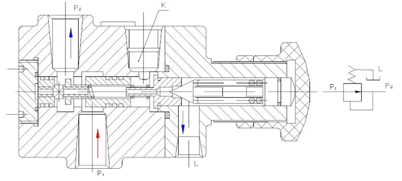
Pressure reducing valves are also divided into direct acting and pilot operated types. The figure below shows the working principle of a pilot operated pressure reducing valve. It is divided into two parts, with the pilot valve regulating the pressure and the main valve reducing the pressure. The hydraulic oil flows in from the inlet and out from the outlet. The pressure at the outlet is lower than at the inlet.
The force balance equation on the main valve spool is:
P2.A=P3A+Fa=P3A+K(x0+x)
Namely
P2=P3+K(x0+x)/A
where
Since the main valve spring only needs to overcome the frictional force of the spool movement, the spring preload is small, and its stiffness is also small. During design, x 0 >>x, so the above equation can be approximately expressed as:
P 2 =P 3 +KX 0 /A= constant
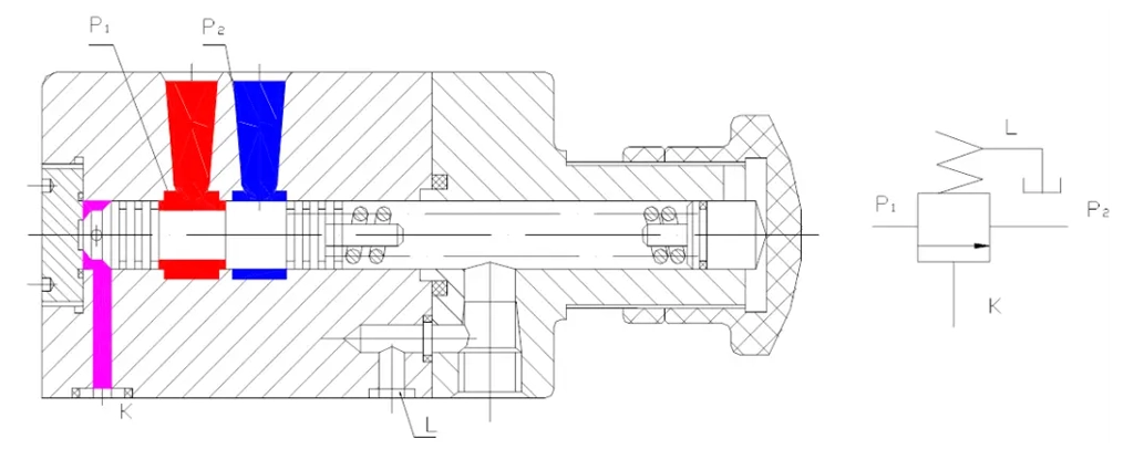
The figure below shows the structure and graphic symbols of a single-stage concentric pressure reducing valve. Compared with a single-stage concentric relief valve, the structure is very similar, but there are obvious differences in the shape of the valve spool and the connection of the oil ports.
The differences are:
The figure below shows the structure of a high-pressure reducing valve. Its principle is basically the same as that of a single-stage concentric pressure reducing valve.
Pressure reduction circuits are often needed in clamping systems, control systems, and lubrication systems. The figure shows a common type of pressure reduction circuit. The maximum pressure of the oil discharged by the hydraulic pump is adjusted by the relief valve according to the needs of the main system.
When hydraulic cylinder A needs a pressure lower than the supply pressure of the pump, a pressure reducing valve can be connected in series in the oil circuit. The pressure reducing valve can maintain a constant pressure after reduction, but it should be at least 0.5MPa lower than the pressure set by the relief valve. When the speed of the actuator needs to be adjusted, the throttle element should be installed at the outlet of the pressure reducing valve.
The figure below shows a two-stage pressure regulating circuit, where the remote control port of the pressure reducing valve is connected to the remote pressure regulation through a two-position two-way solenoid valve to obtain two kinds of preset pressures.
In the illustrated control circuit, the control oil from the hydraulic control pump 2 enters the pressure reducing valve type pilot control valve 3, then by operating the handle of the valve, the hydraulic directional valve 4 in the main circuit can be switched, thus making the hydraulic valve work.
It includes a pilot valve group with two small valves, operated by a handle. The handle can rotate around a ball hinge to apply operating force on any of the small valves. Since each small valve controls a unidirectional action, this type of valve can control the left and right switching actions between the main directional circuits of the main circuit.
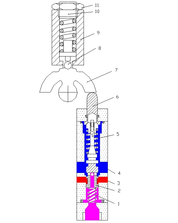
The figure shows the structure of the pressure reducing valve type pilot control valve. When the handle is operated, the push rod 9, the pressure adjusting spring 10, and the valve core 13 move downward. After moving a certain distance, the opening on the valve core 13 faces the P port, allowing the hydraulic oil output from the hydraulic control pump to be reduced to P A and then flow through the A port to the hydraulic control end face of the directional valve, pushing the main directional valve to work, thus achieving speed control and reversing rotation control of the hydraulic motor.
A sequence valve is a pressure valve that can automatically connect or disconnect a certain oil circuit under a certain control pressure.
According to the different control methods, it can be divided into two types: one is the internally controlled sequence valve, which directly uses the pressure at the valve inlet to control the opening and closing of the valve, simply called a sequence valve; the other is the externally controlled sequence valve, which is controlled by external pressure independent of the valve inlet, also called a sequence valve. According to the different structures, it can be divided into direct-acting and pilot-operated sequence valves.
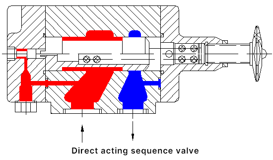
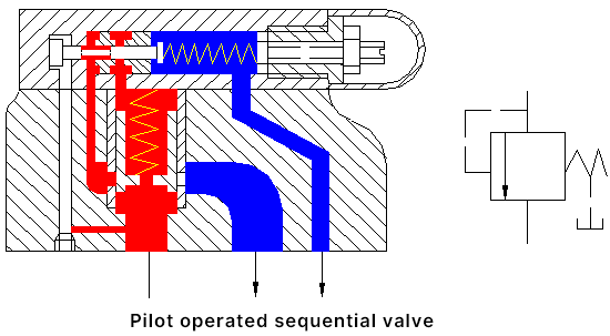
As shown in the figure below, the following two figures are respectively for direct-acting sequence valve and pilot-operated sequence valve. It can be seen from the figure that they are very similar to relief valves. The main difference is that the outlet of the relief valve is connected to the oil tank, while the outlet of the sequence valve is connected to other oil circuits of the system. Therefore, its oil drain port must be connected to the oil tank separately. In addition, the sequence valve has good sealing performance, so the length of the oil seal between the spool and the valve body is longer.
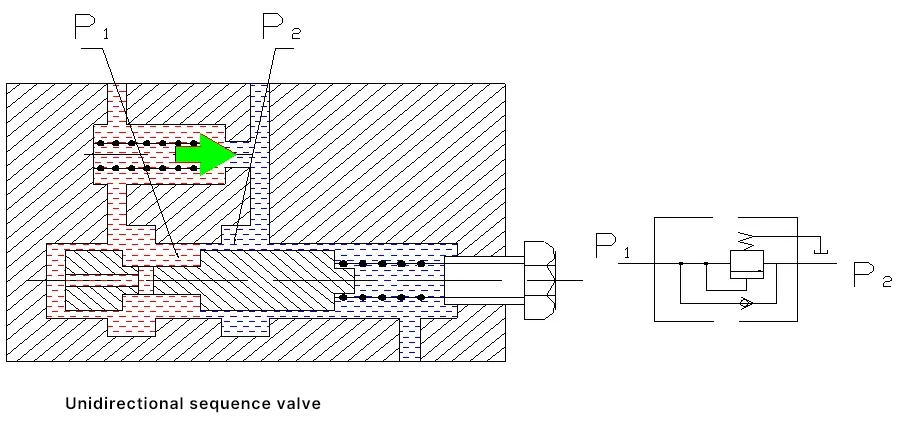
The figure below shows the structural schematic and graphic symbol of the check sequence valve. It is composed of a sequence valve and a check valve in parallel.
When the oil enters from port P 1 , the check valve is closed; when the inlet pressure exceeds the set value of the pressure spring, the sequence valve opens, and the oil flows out from P 2 . When the oil enters from port P 2 , the oil flows out from port P 1 through the check valve.
The figure below shows the structure of a hydraulically controlled sequence valve, which mainly differs from the sequence valve in that the spool is solid, and the pressure oil entering from port P 1 cannot enter the bottom of the slide valve. The control pressure oil at the bottom of the slide valve is introduced from the control port K.
When the control oil pressure exceeds the set pressure of the spring, the valve port opens, connecting port P 1 and P 2 . The opening and closing of the valve port are independent of the inlet pressure of the main oil circuit of the valve but are determined by the level of control oil pressure introduced from control port K.
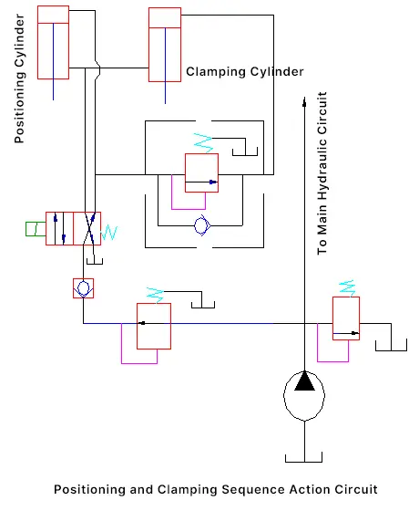
(1) Used to make two or more actuators act in a certain sequence.
The figure below shows a positioning and clamping circuit, which requires positioning first and then clamping. As shown in the figure, the hydraulic pump supplies oil, one route to the main system, and another route through the pressure reducing valve, check valve, and directional valve to the upper chamber of the positioning cylinder, pushing the piston downward for positioning. After positioning, the piston of the cylinder stops moving, the sequence valve opens, and the pressure oil enters the upper chamber of the clamping hydraulic cylinder, pushing the piston downward to clamp.
(2) Used as a back pressure valve
(3) The one-way sequence valve can be used as a balance valve to prevent vertical moving parts from sliding down due to their own weight when the pump is not working.
(4) The pilot-operated sequence valve can be used as a relief valve.
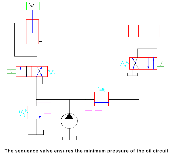
(5) To ensure the minimum pressure in the oil circuit as shown in the figure, the piston of hydraulic cylinder I starts to rise, and only when the pressure exceeds the set pressure of sequence valve A does hydraulic cylinder II act; thus, when hydraulic cylinder II acts, the piston of hydraulic cylinder I will not fall due to the low pressure and its own weight.
A pressure relay is a conversion device that converts pressure signals in the hydraulic system into electrical signals. Its function is to automatically connect or disconnect related circuits according to the changes in hydraulic system pressure, through the micro switch inside the pressure relay, to achieve sequential actions or safety protection, etc.
The figure below shows the structure of a diaphragm-type pressure relay. Its working principle is to control the oil port K to connect to the hydraulic circuit where the hydraulic signal is needed, and then the pressure oil causes the plunger 3 to rise, making the spring seats on both sides touch the outer sleeve shoulder; at the same time, the steel ball moves horizontally causing the lever to rotate around the axis, the other end of the lever presses down the contact of the micro switch, sending out an electrical signal.

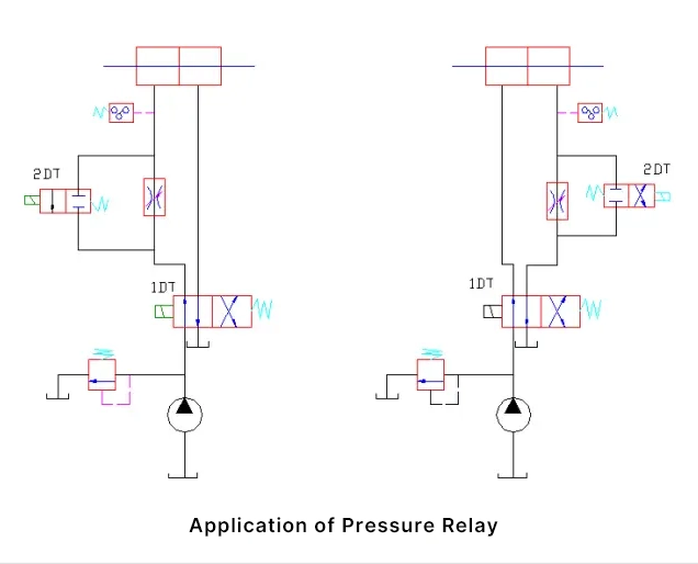
The pressure relay is installed between the throttle valve and the hydraulic cylinder as shown in the left figure, called boost signal sending. Installed in the return oil path, located between the hydraulic cylinder and the throttle valve as shown in the right figure, called zero pressure signal sending.
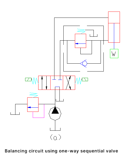
To prevent the vertical hydraulic cylinder and its connected working parts from sliding down due to their own weight, a balance circuit is often used.
The figure below shows a balance circuit composed of check sequence valves. The set pressure of the check sequence valve should be adjusted to balance the weight of the moving parts.
Theoretical stress
P=W/A
where
Due to the presence of the sequence valve, the moving parts will not slide down due to their own weight. The piston only moves downward when the solenoid 1DT is energized, causing the hydraulic pressure in the lower chamber of the cylinder to exceed the set pressure of the sequence valve.
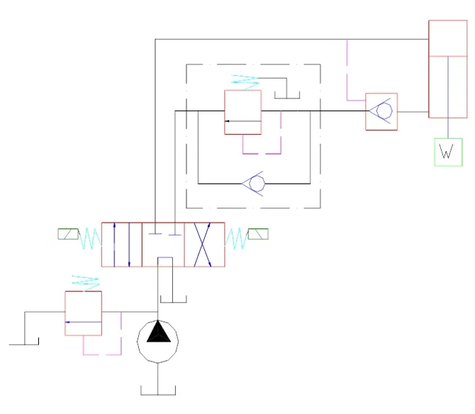
As shown in the figure below, we add a hydraulically controlled check valve between the check sequence valve and the hydraulic cylinder. Because the hydraulically controlled check valve has good sealing when closed, it can prevent the moving parts from slowly sliding down due to leakage of the sequence valve when the three-position four-way solenoid directional valve is in the state of stopping the actuator.
The figure below shows a lifting balance circuit using a hydraulic sequence valve. This circuit is suitable for situations where the balance weight changes. When the directional valve is switched to the right position, the hydraulic cylinder lifts the weight.
When the directional valve is switched to the left position, the piston moves downward to lower the weight. Switching the directional valve to the middle position stops the piston’s movement. The characteristic of this circuit is that the opening and closing of the hydraulic sequence valve depend on the oil pressure at the control port, regardless of the load size.
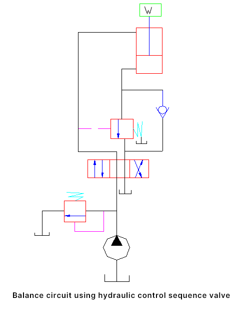
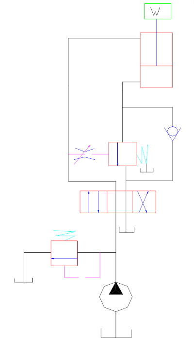
However, the balance circuit in the figure above is imperfect. When the pressure oil opens the hydraulic sequence valve and the piston starts to move downward, the pressure in the upper chamber of the hydraulic cylinder will rapidly decrease, which may cause the hydraulic sequence valve to close and the piston to stop moving.
Subsequently, as the pressure increases, the hydraulic sequence valve opens again, and the piston starts to move. Therefore, the piston continues to descend, creating the so-called “nodding” phenomenon. To solve this problem, a throttle valve can be installed in the control oil circuit to slow down the opening and closing actions of the hydraulic sequence valve. The figure below shows this.
In the working cycle of construction machinery, to maintain a large amount of force, power loss and oil heating will occur. To reduce the loss, the pump should operate under no-load conditions, which is called unloading.
In actual systems, there are two methods of unloading: one is to direct the pump’s output back to the tank, with the pump working at zero pressure, called flow unloading; the other is to keep the pump’s flow at zero while maintaining the original pressure, also called flow unloading. The following introduces several typical unloading circuits.
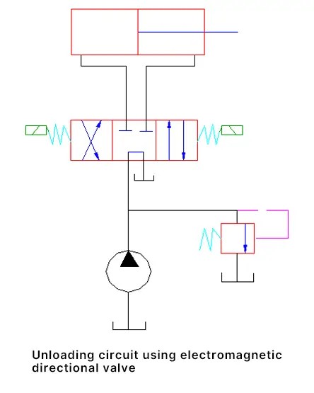
When a three-position directional valve with a middle position function of “H”, “K”, or “M” is in the middle position, the oil output from the pump goes directly back to the tank. The figure below shows this. This method is relatively simple, but it is not suitable for systems where one pump drives two or more actuators.
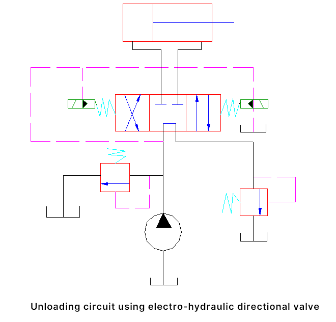
When the flow is large, an electro-hydraulic directional valve can be used, as shown in the figure below. The electro-hydraulic directional valve used in the figure adopts internal control and internal oil return. To provide control oil pressure, a back pressure valve with an adjustment pressure of 0.3 to 0.5 MPa is added to the oil return circuit. This can correspondingly increase the unloading pressure.
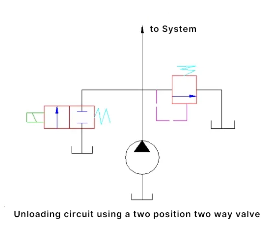
As shown in the figure below, a two-position two-way solenoid valve is specifically added to unload the pump. The flow rate of the two-position two-way solenoid valve must match the flow rate of the pump.
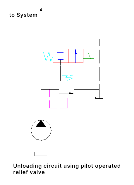
As shown in the figure below, the remote control port of the pilot-operated relief valve can be connected to the tank through a two-position two-way solenoid directional valve. When the solenoid of the two-position two-way valve is energized, the remote control port of the relief valve is connected to the tank, at this time the main valve of the relief valve is fully opened, and all the oil discharged by the pump returns to the tank, unloading the hydraulic pump.
In this circuit, the two-position two-way valve passes only a small amount of flow, so a small flow specification can be used. In products, a small specification solenoid directional valve and a pilot-operated relief valve can be combined together, this combination valve is called a solenoid relief valve.
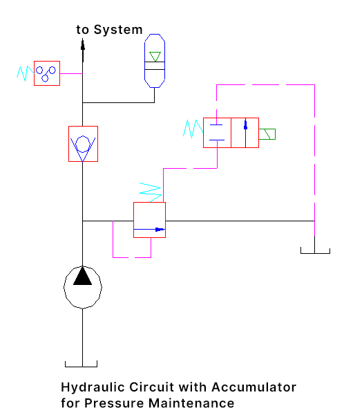
As shown in the figure below, the hydraulic pump supplies oil to both the system and the accumulator. When the pressure reaches the set pressure of the pressure relay, the pressure relay sends a signal, energizing the solenoid of the two-position two-way solenoid directional valve, unloading the hydraulic pump, and the accumulator maintains the system pressure. The maintenance time depends on the system’s leakage, the capacity of the accumulator, and the return interval of the pressure relay, etc.
As shown in the figure below. When the piston moves to the end and stops moving, the pump pressure rises to the maximum value. At this time, the pump’s oil supply is reduced to only compensate for its own leakage and the valve leakage, the pump’s oil supply is small, while the actuator is still maintained at a certain pressure by the pump, and the power consumed by the pump is very small.
In principle, this type of unloading method performs ideally, but the pump itself needs to have a higher efficiency, otherwise, even if the pump is in an unloaded state, its power consumption is still considerable.