Essential Mechanical Parts: A Comprehensive Guide
Are you curious about the invisible forces that keep our world running smoothly? Mechanical parts play a crucial role in…
Figure 1 is the basic structure of a closed single-point press. The composition of an open press includes the frame (bed), transmission system, clutch, brake, connecting rod and slide mechanism, and the drawing cushion under the worktable. Closed presses include closed single-point presses, closed double-point presses, and closed four-point presses.
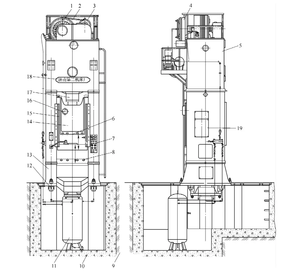
1 – Flywheel
2 – V-belt
3 – Small Pulley
4 – Clutch
5 – Upper Crossbeam
6 – Lower Surface of the Slide
7 – Electric Control Switchboard
8 – Worktable Plate
9 – Foundation
10 – Concrete
11 – Air Tank
12 – Tighten the screw
13 – Machine base
14 – Slider
15 – Guide rail
16 – Lubricating oil hole
17 – Connecting rod
18 – Manufacturer’s nameplate
19 – Technical parameters nameplate
A closed-type press with a slider driven by a single connecting rod is called a closed single-point press; a press with a slider driven by two connecting rods is called a closed double-point press; a press with a slider driven by four connecting rods is called a closed four-point press. Closed multi-point presses not only have large tonnage but also have extra-large worktable sizes, suitable for the stamping of large and extra-large parts, such as car bodies, large vehicle cover parts, etc.
The transmission system of a closed mechanical press is much more complex than that of an open press, mainly including the main motor, small pulley, V-belt, large pulley and flywheel, clutch and brake, gears, crankshaft or eccentric wheel, headstock (upper crossbeam), transmission shaft, and spindle, etc.
The transmission system is the heart of the mechanical press. Its nominal pressure F 公称 , the stamping force required by the stamping process, and the stamping work are all realized through the operation of the transmission system.
At the same time, it also directly implements the number of strokes per minute of the slider, and the stamping force and stamping work output at different angular positions of the crankshaft’s crank. Therefore, the transmission system is the most important and critical component of the mechanical press.
The power for the operation of the transmission system of a mechanical press comes from the electric motor. When the electric motor is powered on and starts, the rotational power of the motor is transmitted to the flywheel through the small pulley on the outer end of the motor shaft via the V-belt.
In the non-working state, the clutch is disengaged, and the flywheel rotates freely to store energy, ready to output sufficient stamping work during stamping processing; once the clutch is engaged, the rotational power of the electric motor can drive the crankshaft through the clutch, pulling the connecting rod mounted on the crank of the crankshaft, and dragging the slider to reciprocate vertically up and down along the stamping direction within the guide rail.
Presses use motors with large power, slow start-up, and large starting current. When the motor stops, it must take some time to come to a complete stop due to the inertia of the rotor’s rotation. The combination of the clutch and brake can control the mechanical press to start or stop while the motor is rotating, meeting the requirements of high-speed stamping and instantaneous stopping of the mechanical press.
Clutches used in Chinese-made open presses, especially those with a nominal pressure of 1600kN or less, mostly adopt rigid clutches with simple structure and low cost. There are many types of clutches for mechanical presses, generally divided into rigid clutches and friction clutches.
Common rigid clutches include toothed clutches, sliding pin clutches, and turning key clutches. Among them, the turning key clutch has better performance and has now replaced toothed clutches and sliding pin clutches and is widely used in Chinese-made open mechanical presses.
Advantages of rigid clutches: simple and compact structure, small size, easy to manufacture, easy to maintain, low manufacturing cost, and low usage cost, no need for compressed air. Its disadvantages: small torque transmission, unable to stop the slider at any position, unsafe operation, accompanied by impact and vibration when engaged.
The application of rigid clutches is more suitable for small open presses. Because the tonnage is small, the transmitted torque is also not large. To reduce the impact when engaging, the rigid clutch can be installed on the crankshaft. Small presses generally have a low height, and the slider is small. When adjusting the die, the flywheel can be manually rotated without needing to jog the stroke standard.
Figure 2 shows the widely used double turning key clutch. Its structure and action process are as follows:
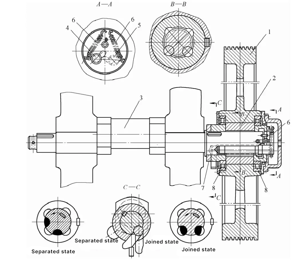
1 – Flywheel
2 – Engagement sleeve
3 – Crankshaft
4, 5 – Turning keys
6 – Spring
7 – Cam plate
8 – Bearing
The flywheel 1 contains a coupling sleeve 2 with four semi-circular grooves, and two turning keys 4 and 5 are fitted into the two notches at the right end of the crankshaft 3. The sequence of operation: when the tail end of the turning key 4 on the left loses control of the operating mechanism (see Figure 3), the right ends of turning keys 4 and 5 rotate a certain angle under the action of spring 6, putting both turning keys into the engaged working state, and the press starts.
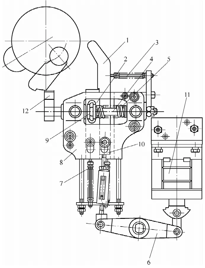
1 – Sword plate
2 – Rack
3, 5, 7 – Spring
4 – Camshaft
6 – Lever
8 – Housing
9 – Gear
10 – Pull rod
11 – Electromagnet
12 – Cam
When the press stops, it is the cam 12 in Figure 3 that returns to its original position. When the tail end of the turning key 4 on the left touches this part, it causes the turning key 4 to rotate back and lie down into the crankshaft slot. At the same time as the turning key 4 rotates back, its right end pawl actuates the pawl on the right end of the turning key 5, also causing the turning key 5 to rotate into the crankshaft’s notch, and the flywheel idles.
Figure 3 shows the operating mechanism of the turning key clutch. The housing 8 is mounted on the bed wall underneath the turning key clutch, using the swing of the cam 12 to control the engagement and disengagement of the clutch. This operating mechanism can achieve two standards for the small press: single stroke and continuous stroke.
When the press starts a single stroke, it is necessary to fit the upper end of the pull rod 10 onto the pin at the lower end of the sword plate 1. After the electromagnet 11 is energized, it pulls the right end of the lever 6 upward, and the left end pulls the pull rod 10 downward, causing the sword plate 1 to also move downward. The sword plate 1 presses the rack 2 to move downward, rotating the gear 9. Since the gear 9 is keyed to the camshaft 4, the camshaft 4 also rotates.
Similarly, the cam 12 on the left end of the shaft swings, and the tail end of the turning key 4 in Figure 2 loses control, causing the key to engage with the crankshaft and start the slider. When the crankshaft rotates one round, the cam plate 7 mounted on the crankshaft in Figure 2 pushes the sword plate 1 to swing to the right, the rack 2 loses control of the sword plate 1, and moves upward under the action of spring 7.
The gear 9 reverses, causing the cam 12 to return to its original position, while blocking the tail end of the turning key. The turning key 4 in Figure 2 lies down into the crankshaft’s notch, the clutch disengages, and the belt-type brake on the other end of the crankshaft stops the slider from moving.
When the press starts a continuous stroke, it is necessary to fit the upper end of the pull rod 10 directly onto the pin at the lower end of the rack 2. When the electromagnet 11 is energized, the lever 6 directly pulls the rack 2 downward, rotating the gear 9, swinging the cam 12, and engaging the clutch. After the electromagnet 11 is de-energized, due to the action of spring 7, the rack 2 moves upward, causing the cam 12 to return to its original position, the clutch disengages, and the slider stops moving.
The open-type mechanical press uses three types of rigid clutches: the so-called tooth-embedded clutch, which engages by lateral insertion of teeth; the sliding pin, also known as the pin-type clutch; and the turning key clutch, which engage by inserting a sliding pin or rotating a key body to transmit rotational power (torque).
These clutches use rigid connecting elements such as teeth, pins, and keys for a hard connection, forcibly joining the flywheel’s drive shaft with the crankshaft as one, transmitting the rotational power (torque) from the electric motor through the drive shaft to the main shaft (crankshaft), and then pulling the slider up and down along the guide rail through the connecting rod to perform stamping processing.
The main disadvantages of this type of rigid clutch: during engagement, there are impacts and vibrations and noise is generated, polluting the environment; it is not possible to stop the slider at any position, making operation unsafe; disengaging to stop the crankshaft, the slider can only stop near the crankshaft’s near dead point, and adjusting the die requires manually moving the flywheel to obtain an inching stroke, which is inconvenient and unsafe.
More importantly, if during the downward closing and pressing of the die, it is discovered that there are foreign objects in the mold work area that urgently need to be cleared, or the material feed is not in place and needs adjustment, or hands are unintentionally extended into the mold work area without time to withdraw or unable to withdraw immediately, or the danger of crushing fingers is not yet realized…
The moment the upper die punches down, although the main operator notices the danger and quickly operates the separation switch to stop the slider, even if the clutch is disengaged, the slider will still move downward, completing a stroke before returning to the top dead point to stop. Mold accidents, equipment accidents, or even personal safety accidents are inevitable!
Figure 4 shows the belt-type brake mounted on the other end of the crankshaft. Its function is to brake the movement of the slider after the clutch disengages, stopping the press.
The brake wheel is keyed onto the crankshaft. The brake housing is mounted on the bed. The friction material on the inner surface of the brake band rubs against the outer surface of the brake wheel, generating braking torque. The adjusting screw can adjust the magnitude of the braking torque.
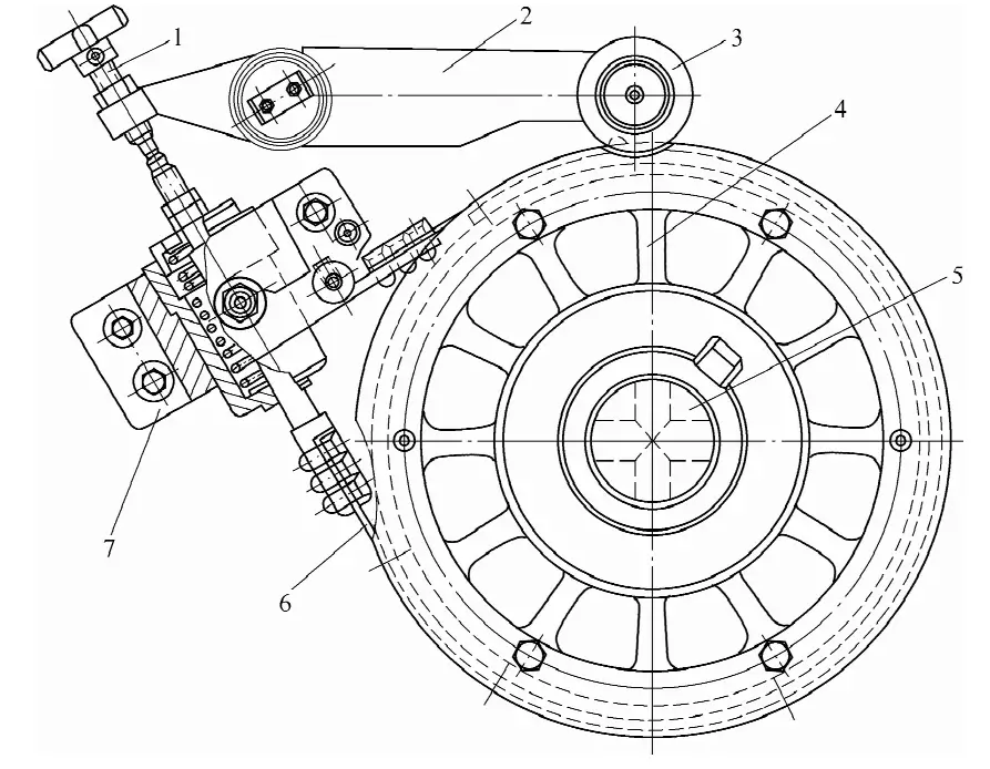
1 – Adjusting screw
2 – Brake lever
3 – Roller
4 – Brake wheel
5 – Crankshaft
6 – Brake band
7 – Brake housing
Medium and large presses all use friction clutches. The advantages of this type of clutch are: it transmits a large torque; it can realize various standardized operations, such as single stroke, automatic continuous stroke, inching adjustment stroke, etc.; adjusting the mold is relatively convenient, and the clutch engages smoothly with little impact. The disadvantages are: complex structure; large dimensions; relative slipping between friction plates consumes a considerable amount of energy and generates a large amount of heat.
There are many types of friction clutches, including dry and wet types, single-disc pad type and multi-plate type. Their power sources include pneumatic, hydraulic, and electromagnetic, etc. Figure 5 shows a single-disc pad type friction clutch that is widely used both domestically and internationally.
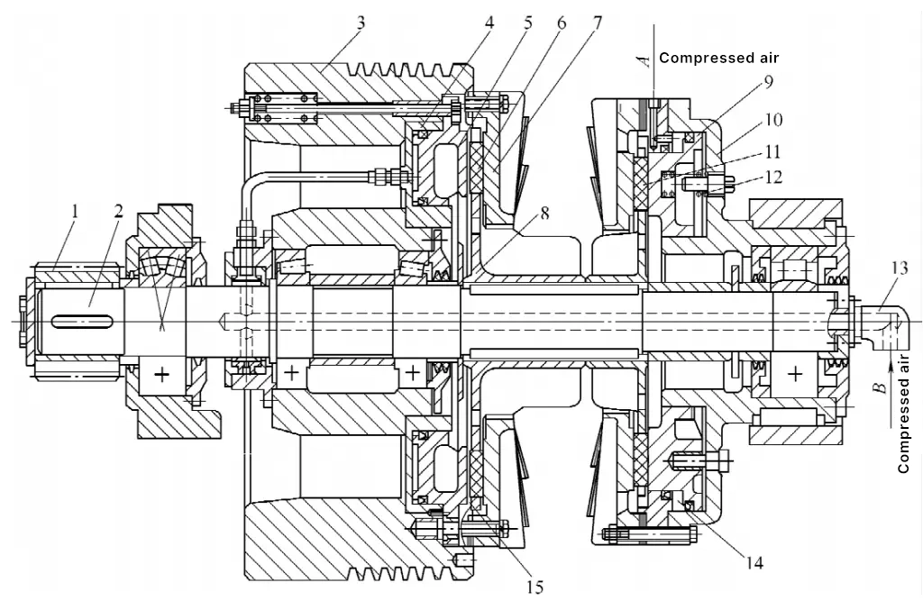
1 – Small gear
2 – Clutch shaft
3 – Flywheel
4 – Engagement cylinder
5 – Piston
6, 11 – Friction block
7 – Friction plate
8 – Friction block tray
9 – Piston
10 – Brake cylinder
12 – Spring
13 – Air intake
14 – Brake
15 – Clutch
The clutch and brake are mounted on the same shaft, with the clutch also mounted on the flywheel, and the brake housing fixed together with the press body. When the press is stopped, the flywheel 3 idles on the clutch shaft 2. When starting the press, the compressed air from the air distribution valve is divided into two paths, A and B, entering the brake and clutch.
Due to the time difference of the air valve, the compressed air from path A enters the brake cylinder 10 first, pushing the piston 9 to the right to disengage from the friction block 11, while compressing the spring 12.
The compressed air from path B enters the engagement cylinder 4 of the clutch from the right end of the shaft through the air intake 13 and the holes in the clutch shaft 2, pushing the piston 5 to the right, pressing the friction block 6 tightly against the friction plate 7. At this point, the flywheel drives the friction block tray 8 and the clutch shaft 2 to rotate, driving the transmission system of the press through the small gear at the left end of the clutch shaft 2.
When the press is stopped, the air distribution valve controlling the two cylinders is de-energized simultaneously. Due to a time difference in the distribution valve, the clutch cylinder vents first, disengaging the clutch. Then the brake cylinder vents, and under the action of the spring, the movement of the press’s slide is braked.
The connecting rod and slide system, as shown in Figure 6. This is a single-point press connecting rod and slide system. The connecting rod is mounted on the crank of the crankshaft, and the rotational motion of the crankshaft is converted into the reciprocating linear motion of the slide. The connecting rod converts the torque of the crankshaft into the punching force of the slide on the workpiece.
1 – Linkage Cover
2 – Linkage
3 – Adjusting Screw
4 – Slider
5 – Adjusting Motor
6 – Turbine
7 – Collapsing Block
8 – Ejector Rod
9 – Linkage Tile
The linkage consists of two main parts: the linkage and the adjusting screw. The upper end of the linkage is connected to the crankshaft’s crank, and the lower end of the screw is connected to the slider.
The slider mechanism includes the slider body, closed height adjustment mechanism, balancing device, overload protection device, and material return device, etc.
The lower surface has a trapezoidal groove or threaded hole for fixing the upper base plate of the punch die.
The closed height adjustment mechanism is set up to accommodate molds of different closed heights to be installed on the same press, so that punch dies with various closed heights can work on the same press.
For large and medium-sized presses, especially closed single-point presses, closed double-point presses, and closed four-point presses, the slider is heavy, and generally, a motorized adjustment mechanism is used. This mechanism consists of a dedicated motor and a set of reduction gears, and the closed height can be automatically adjusted by simply turning on the motor switch. For small presses, due to the smaller mass of the slider, the closed height can generally be adjusted manually with a dedicated wrench.
For closed presses, especially large-tonnage closed single-point, closed double-point, and closed four-point presses, the slider is heavy, and together with the upper die fixed on the slider, the mass is measured in tons, some even weighing dozens of tons.
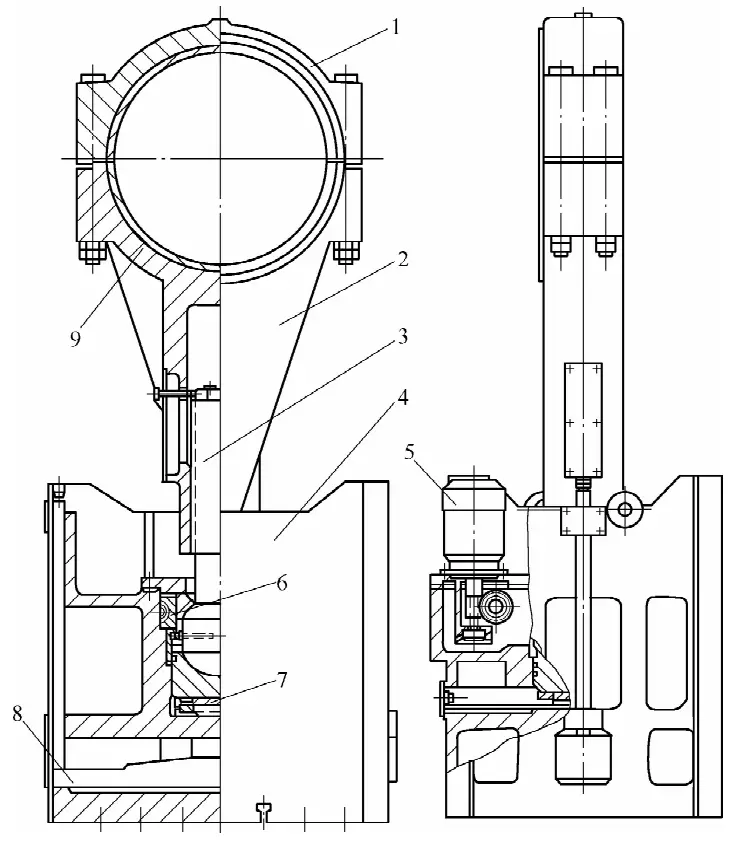
During the stamping process, such a heavy slider combined with the punch die can have an adverse effect on the stability of the vertical structure of the press. Therefore, pneumatic balancers are widely used on large and medium-sized closed presses, with the functions of:
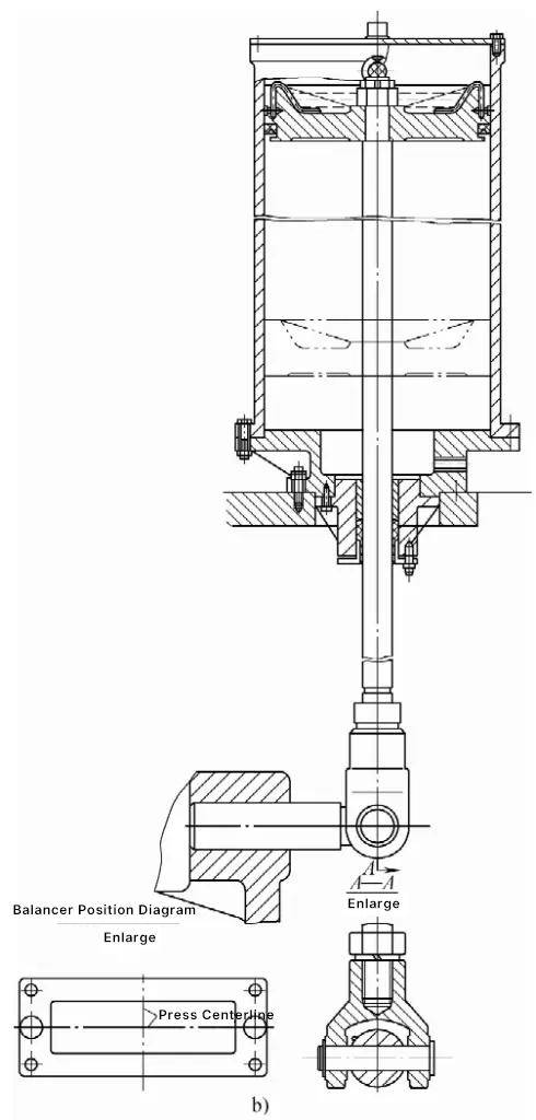
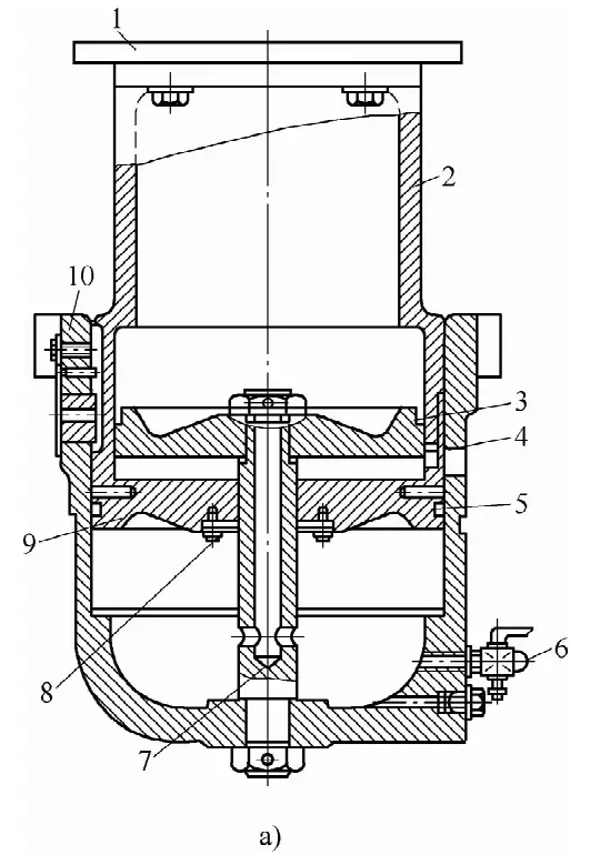
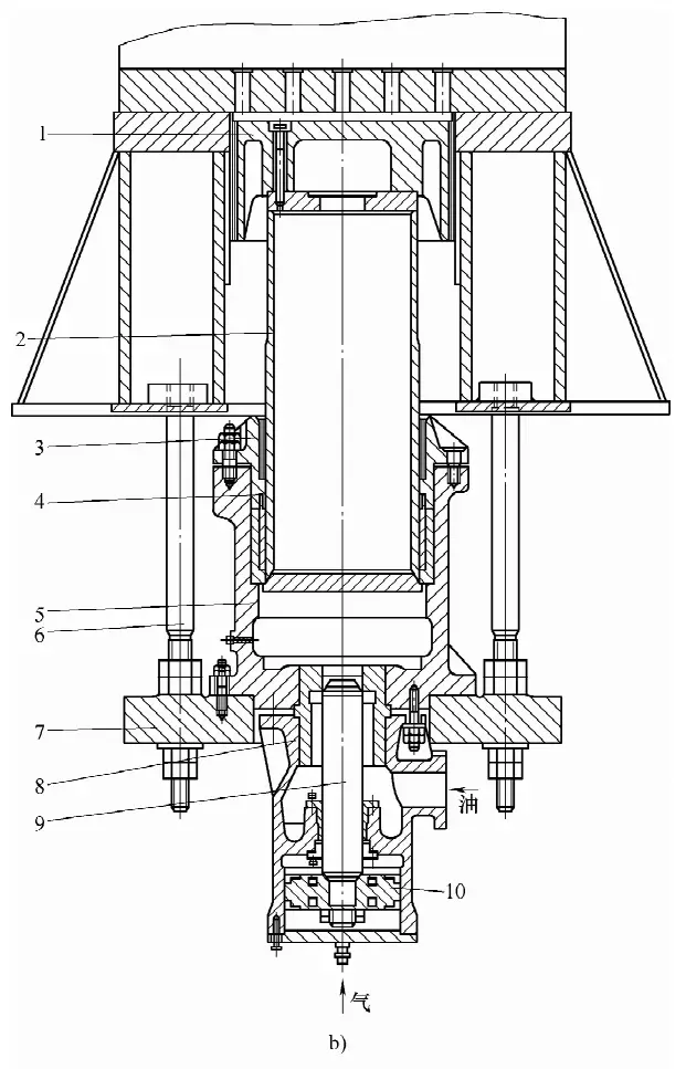
The typical structure of the balancer is shown in Figure 7.
a) Balancer for J31-400 Type Closed Single-Point Press
b) J36-400 type closed double-point press balancer
The installation position of the balancer depends on the overall layout of the press and should not overlook the convenience of maintenance. Typically, the balance cylinders are mounted on the top surface of the crossbeam, the front and rear sides of the crossbeam, or inside the left and right columns, with a number varying from 2 to 4, and heavy presses can have up to 6 balance cylinders. The resultant force line of each balancer must pass through the center of gravity of the slide block to prevent the slide block from tilting due to uneven force and not operating smoothly.
Mechanical presses are equipped with a blanking device inside the slide block, which is used to push the stamped parts out of the die during the return stroke of the slide block, or to unload the excess material from the punch. On open presses, rigid blanking devices are commonly used.
Common rigid blanking devices include exposed and concealed types, with the exposed type being more commonly used. In fact, a crossbar (also called a crossbeam), a rigid blanking device, is installed inside the slide block. Large and medium-sized closed presses often use pneumatic blanking devices.
During the stamping process of a mechanical press, the actual stamping force generated exceeds the allowable pressure of the press, which is considered an overload. Overloading the press can cause deformation or even damage to load-bearing parts of the press, such as the crankshaft and transmission gears, leading to equipment accidents.
Since the allowable pressure of the press depends on the bending strength of its crankshaft and the shear strength of the gear teeth profile, while the power of the press depends on the stored energy of its flywheel and the output power of the electric motor and its allowable overload capacity. When selecting a press, if only the pressure is calculated, the flywheel speed of the press may drop sharply due to power overload, causing the electric motor to slip, the coil to overheat, and burn out.
The nominal pressure of the press is the maximum pressure generated by the slide block before it reaches the bottom dead point during its entire stroke, and the pressure at the midpoint of its stroke is the smallest, only half of its nominal pressure. This is very important for extrusion, deep drawing, and punching thick plates, and should be carefully calculated. The press’s pressure-stroke curve should be compared with the pressure-stroke curve of different stamping processes of the stamped parts to control the actual stamping force not to overload.
Overloads of the press and phenomena that may cause overloads occur frequently at the stamping site: improper selection of the press; loose die screws, resulting in die misalignment and top die ejection; die adjustment loss; material thickness tolerance or increased thickness; excessive variance in blank volume; change in material grade with increased strength (resistance to deformation); die edge blunting or even chipping; stacked materials entering the die or foreign objects inside the die, etc. All of these can potentially cause equipment damage and accidents, necessitating the installation of overload protection devices inside the slide block, that is, overload protection devices.
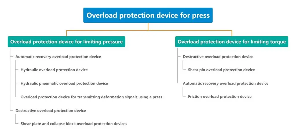
There are many types of overload protection devices for mechanical presses, as shown in Figure 8.
Commonly used overload protection devices for mechanical presses are shown in Figure 9.
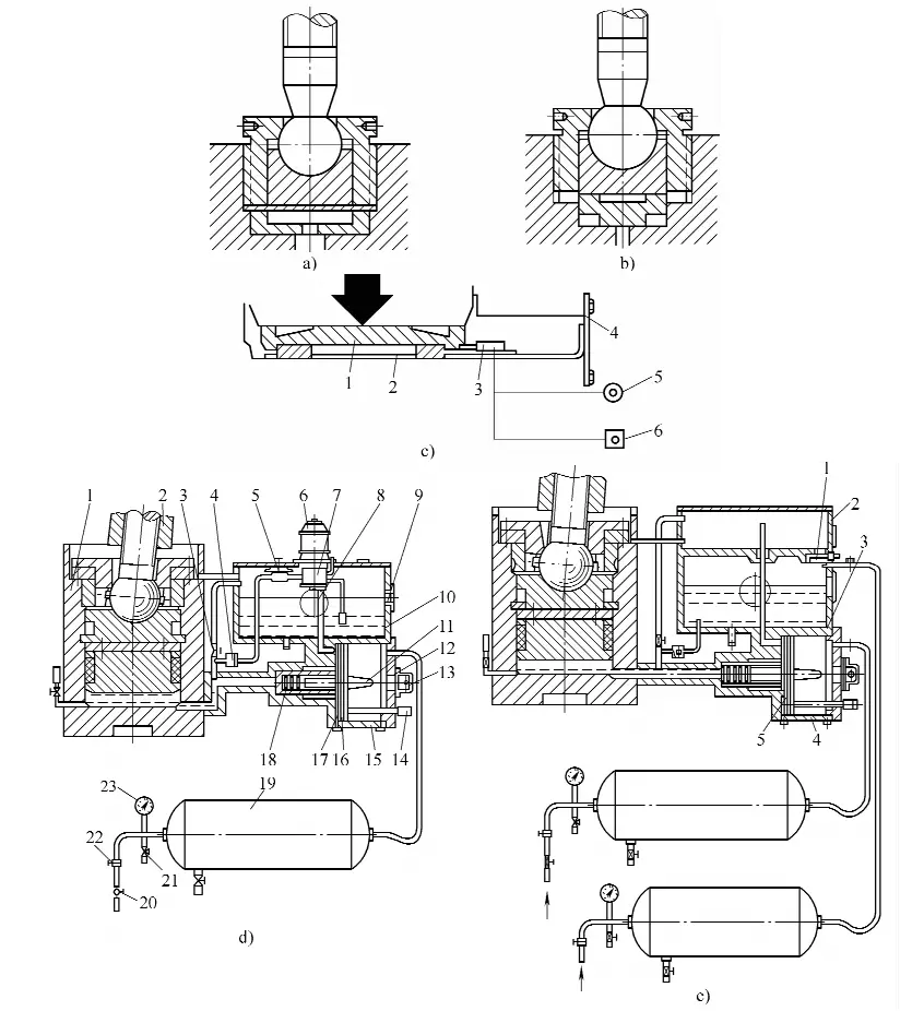
a) Shear plate type overload protection device
b) Collapsible block type overload protection device
c) German collapsible block type overload protection device
1-Pressure block
2-Pad
3-Travel switch
4-Lower cover
5-Red signal light
d-Button
d) German overload protection device with hydraulic pump
1-Slide block
2-Connecting rod
3, 20, 21-Gate
4-Check valve
5-Adjusting valve
6-Electric motor
7 – Hydraulic Pump
8 – A Pair of Trachea
9 – Oil Gauge
10 – Fuel Tank
11 – Tail Rod
12 – Crushing Disc
13 – Cover
14 – Push Rod
15 – Supercharging Cylinder
16 – Supercharging Piston
17 – A Pair of Cylinders
18 – Unloading Valve Core
19 – Air Storage Cylinder
22 – Pressure Reducing Valve
23 – Pressure Gauge
e) German Overload Protection Device without Hydraulic Pump
1 – Valve
2 – Upper Oil Tank
3 – Lower Oil Tank
4 – Boost Cylinder
5 – Boost Piston
During the deep drawing process of sheet metal, to prevent wrinkling due to a high degree of deformation, edge pressing deep drawing is usually adopted. The deep drawing pad is specifically designed to provide the edge pressing force. In addition, the deep drawing pad can also provide the ejection force for ejecting the formed stamping parts from the concave die, including punching and various forming, volume stamping parts.
Small presses do not install deep drawing pads, and the edge pressing and ejection of deep drawn parts are all undertaken by the die. There is no difficulty in the structural design of the die.
There are four structural forms of the deep drawing pad: rubber type, spring type, pure pneumatic type, and a combination of pneumatic and hydraulic type. Deep drawing pads that use elastic elements such as rubber and springs to provide edge pressing force and ejection force are mostly installed on the die, suitable for small, shallow deep drawing stamping parts and dies with small ejection force. For stamping on small open presses with nominal pressure F 公称 ≤1000kN, this type of deep drawing pad is often used.
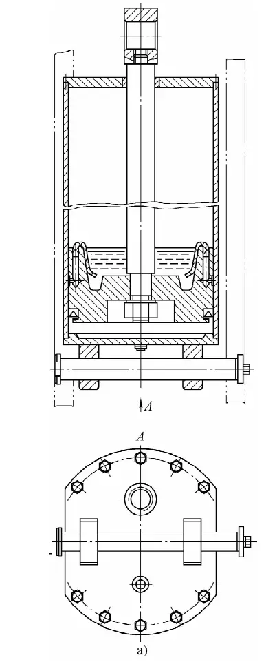
Large and medium-sized mechanical presses are closed presses with nominal pressure F 公称 ≤1600KN, including closed single-point presses, closed double-point presses, closed double-action double-point deep drawing presses, and closed four-point presses, generally use the two types of deep drawing pads shown in Figure 10.
a) Pneumatic Deep Drawing Pad
1 – Spacer plate
2 – Piston cylinder
3, 5, 8 – Sealing rings
4 – Fixed piston
6 – Air release valve
7 – Fixed piston rod
9 – Movable plug
10 – Cylinder body
b) Hydraulic deep drawing pad
1 – Tray
2 – Plunger
3 – Flange
4 – Sealing ring
5 – Hydraulic cylinder
6 – Bolt
7 – Base plate
8 – Locking cylinder body
9 – Valve stem
10 – Piston
Mechanical presses widely use compressed air to drive some components and during the stamping process, or to replace manual labor for various automation tasks. Large and medium-sized mechanical presses use pneumatic friction clutches, brakes, deep drawing pads, balance cylinders, manipulators, as well as blowing off stamped parts from the mold, cleaning the press worktable and mold work area, all driven or blown off by 0.4~0.6MPa compressed air.
Pneumatic transmission has the advantages of rapid action, simple maintenance, clean medium, and the convenience of centralized production supply and long-distance transportation of compressed air. At the same time, compressed air has a wide range of sources, low cost, and is an indispensable basic production material for manufacturing factories. The press production only needs to connect to the air main to input.
The moving, adjustable parts used on the press, especially those with relative motion (fitting) surfaces, should be lubricated to reduce the wear of machine parts, maintain the factory precision and technical condition of the press for as long as possible, improve its service life, and at the same time reduce energy consumption and maintenance costs.
Lubricants for mechanical presses can be divided into two categories: lubricating oils and greases. Commonly used lubricating oils include L-AN32, L-AN46, L-AN68, L-AN100 oils for total loss systems. Commonly used greases include No. 2, No. 3, No. 4 calcium-based greases and No. 2, No. 3, No. 4 sodium-based greases.
The lubrication methods adopted by general mechanical presses are centralized lubrication and dispersed lubrication. Centralized lubrication is provided by a multi-outlet lubrication device that can supply oil to multiple designated lubrication points. Grease centralized lubrication can be implemented with motor pumps or manual pumps. If centralized lubrication with lubricating oil is used, it can achieve circulating lubrication.
Distributed lubrication treats each lubrication point specified in the design as part of a lubrication system diagram, setting lubrication cycles as needed. Lubrication is performed on time and at the designated points. This method of lubrication requires the installation of devices such as covered oil cups, pressure grease nipples, oil lines, and ordinary oil cups for holding oil for lubrication.