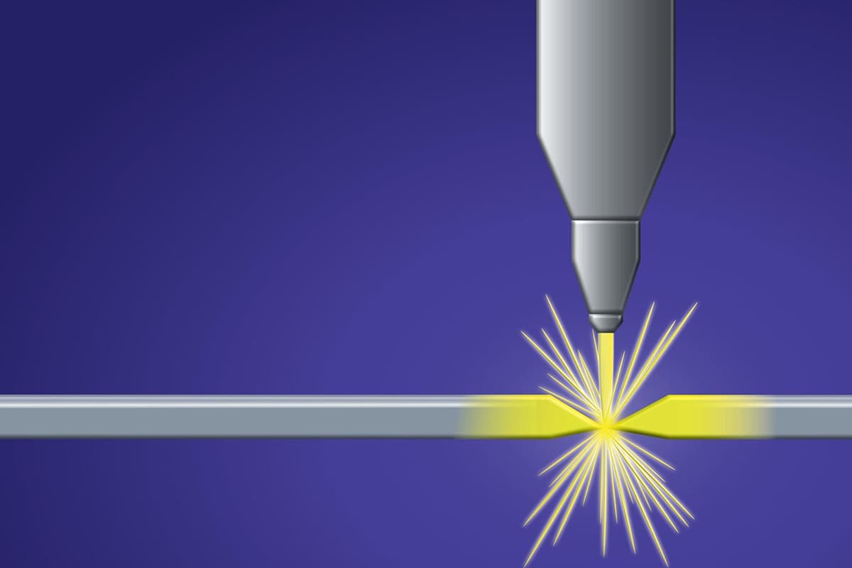
Plasma cutting

Plasma cutting is a high-precision thermal cutting process that utilizes a high-energy density, constricted arc and high-velocity plasma flow to melt and expel metal, creating a clean, continuous cut. This advanced technique ionizes gas to form plasma, which is then directed through a fine-bore copper nozzle to concentrate the energy.
The plasma arc cutting process offers several advantages over traditional methods:
- Speed: It achieves cutting speeds significantly faster than oxy-fuel cutting, especially for materials under 25mm thick.
- Minimal heat-affected zone: Due to its concentrated energy and rapid cutting action, plasma cutting introduces less heat into the workpiece, resulting in reduced thermal distortion and improved cut quality.
- Versatility: Suitable for cutting a wide range of conductive metals, including steel, aluminum, stainless steel, and other alloys.
- Precision: Capable of producing narrow kerf widths and maintaining tight tolerances, particularly with computer numerical control (CNC) integration.
However, plasma cutting does present some challenges:
- Environmental concerns: The process generates considerable noise, fumes, and particulate matter, necessitating proper ventilation and operator protection.
- Thickness limitations: While highly efficient for thinner materials, plasma cutting becomes less economical compared to oxy-fuel cutting for carbon steel plates exceeding 25mm in thickness.
- Initial cost: Plasma cutting systems generally require a higher initial investment than oxy-fuel equipment.
It’s worth noting that plasma technology extends beyond cutting applications. The versatility of plasma arc systems allows for welding, spraying, hardfacing, and gouging operations, making it a valuable multi-purpose tool in metal fabrication.
To optimize plasma cutting performance and mitigate its drawbacks, consider implementing water tables for noise reduction and fume control, as well as investing in high-definition plasma systems for enhanced cut quality and reduced environmental impact.
Characteristics and classification of plasma arc cutting
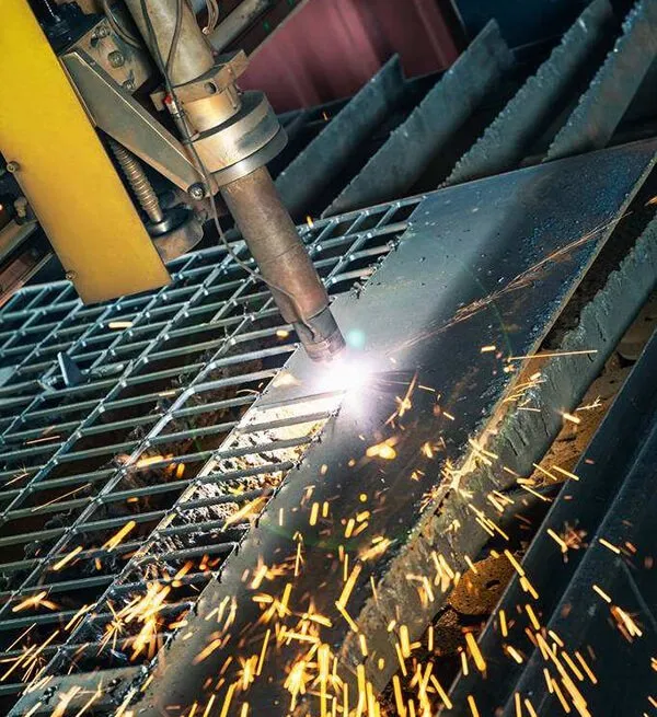
1.1 Characteristics of Plasma Arc Cutting
Plasma arc cutting utilizes a highly compressed, high-temperature arc between a cathode (typically a tungsten electrode) and an anode. This process creates a plasma jet characterized by high ionization, energy density, and flow rate.
The cutting mechanism involves forcing the arc and inert gas through a small-diameter nozzle, producing an extremely hot, high-velocity jet. This concentrated arc energy melts the workpiece material, while the high-temperature expanded gas jet expels the molten metal through the kerf.
When cutting ferrous materials like carbon steel or cast iron, oxygen can be added to the gas stream to provide additional exothermic energy, enhancing the cutting process.
Key advantages of plasma arc cutting include:
- Versatility: Can cut a wide range of metals and some non-metallic materials that are challenging for conventional methods.
- Speed: Significantly faster than oxy-fuel cutting, especially for thin materials (up to 5-6 times faster for thin carbon steel).
- Quality: Produces bright, clean cuts with minimal thermal distortion, ideal for precision parts.
- Flexibility: Suitable for cutting complex shapes and profiles.
However, plasma cutting also has some limitations:
- Kerf width and bevel angle tend to be larger compared to other methods, though special nozzles and techniques can mitigate this for thin materials.
- Thick plate cutting capability is inferior to oxy-fuel cutting.
- Higher equipment costs and power consumption compared to oxy-fuel systems.
- Potential safety concerns due to high voltage, arc radiation, smoke, and noise.
Plasma arc cutting equipment typically requires:
- Power supply: 25-200 kW, with cutting currents ranging from 30-1000 A and high no-load voltage.
- Gas supply: Argon or nitrogen-hydrogen mixtures, depending on the application.
- Water-cooled torch for heat management.
Both manual and automated plasma cutting systems are available. Manual cutting requires similar skills to oxy-fuel cutting but with additional parameter control. Automated systems offer higher precision and productivity, often incorporating water tables or jackets for noise and fume reduction.
In conclusion, plasma arc cutting offers significant advantages in speed, versatility, and cut quality for a wide range of materials and thicknesses. However, considerations of equipment cost, safety requirements, and limitations on very thick materials must be weighed against these benefits when selecting a cutting process.
1.2 Working Principle of Plasma Arc Cutting
Plasma arc cutting utilizes an extremely high-temperature plasma arc, typically ranging from 10,000°C to 14,000°C, which significantly exceeds the melting point of all known metals and non-metals. This extreme heat enables the cutting of a wide variety of materials, including most metallic and non-metallic substances.
Developed in the 1950s, plasma arc cutting was initially employed to cut metal materials that were challenging for traditional oxygen-acetylene flame cutting, such as aluminum alloys and stainless steel. As the technology evolved, its application expanded to include carbon steel and low alloy steel, making it a versatile cutting method in modern manufacturing.
The fundamental design of a plasma arc cutting torch closely resembles that of a plasma arc welding torch. However, the key difference lies in the gas flow characteristics:
- Welding application: Utilizes a low-velocity ionized gas flow to melt the base metal, forming a welded joint.
- Cutting application: Employs a high-velocity ionized gas flow to melt the base metal and forcefully expel the molten material, creating a kerf.
The effectiveness of the plasma arc for cutting is determined by several factors:
- Type of ionized gas
- Gas pressure
- Current intensity
- Nozzle channel geometry (aspect ratio)
- Standoff distance between the nozzle and workpiece
Figure 4.1 illustrates the basic structure of a plasma arc cutting torch.
In plasma arc cutting operations, the power supply is exclusively configured for DC positive polarity, with the workpiece connected to the positive electrode. This setup ensures optimal energy transfer and cutting performance.
When cutting metal, a transferred arc is employed. The method of initiating this transferred arc depends on the specific cutting torch design. Plasma arc cutting torches can be categorized into two main types:
- Pilot arc (maintenance arc) cutting torch
- Non-pilot arc (non-maintenance arc) cutting torch
Figure 4.2 depicts the circuit wiring diagram for a pilot arc cutting torch. The non-pilot arc cutting torch circuitry is similar but lacks the resistive branch present in the pilot arc configuration. This difference in design affects the arc initiation and stability characteristics of each torch type.
Understanding these principles and equipment configurations is crucial for optimizing plasma arc cutting processes in industrial applications, ensuring efficient and high-quality cuts across a wide range of materials.
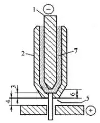
Fig. 1 basic structure of plasma arc cutting gun
- 1. Electrode;
- 2. Compression nozzle;
- 3. Compress the nozzle channel length;
- 4. Distance from nozzle to workpiece;
- 5. Compress the nozzle aperture;
- 6. Electrode retraction distance;
- 7. Lonic gas.
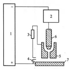
Fig. 2 basic circuit of maintenance arc cutting gun
- 1. Power supply;
- 2. High frequency arc starter;
- 3. Resistance;
- 4. Contactor contact;
- 5. Compression spray;
- 6. Electrode;
- 7. Workpiece.
The function of the resistor in Fig. 2 is to limit the arc maintenance current to the lowest value that can smoothly ignite the transfer arc.
High frequency arc starter is used to ignite the maintenance arc.
When the arc is struck, the contact of the contactor is closed, and the high-frequency arc starter generates high-frequency and high-voltage to ignite the maintenance arc.
After the maintenance arc is ignited, when the cutting gun approaches the workpiece, the high-speed plasma flame from the nozzle contacts the workpiece to form a path between the electrode and the workpiece, so that the arc is transferred between the electrode and the workpiece.
Once the transfer arc is established, the maintenance arc is automatically extinguished, and the contact of the contactor is automatically disconnected after a period of time delay.
Laser cutting
Laser cutting is an advanced and widely used cutting technology in material processing.
It is a processing method that uses a high-energy density laser beam as a “cutting tool” to thermally cut materials.
Laser cutting technology can be used to cut various kinds of metal, non-metal plates, composite materials and hard materials such as tungsten carbide and titanium carbide, and has been widely used in national defense construction, aerospace, engineering machinery and other fields.
Laser cutting principle, classification and characteristics
2.1 Laser cutting principle and classification
(1) Principle of laser cutting
Laser cutting is a precision thermal cutting method that utilizes a focused, high-power density laser beam to process materials. When the laser beam irradiates the workpiece, it rapidly heats the material to its melting point, vaporization temperature, or ignition point, depending on the material properties and desired outcome. Simultaneously, a high-velocity gas stream, typically nitrogen or oxygen, is directed coaxially with the laser beam to expel the molten material from the kerf, resulting in a clean, precise cut.
The process involves several key mechanisms:
- Absorption: The material absorbs the laser energy, converting it to heat.
- Melting: The localized heat causes the material to melt in a confined area.
- Vaporization: Some materials may partially vaporize, especially at higher power densities.
- Chemical reaction: In the case of oxygen-assisted cutting, an exothermic reaction can occur, enhancing the cutting process.
- Melt ejection: The coaxial gas jet removes the molten material, creating the cut.
Laser cutting offers several advantages, including high precision, minimal heat-affected zone, ability to cut complex geometries, and suitability for a wide range of materials, from metals to non-metals.
See Fig. 3 for a schematic representation of the laser cutting principle.
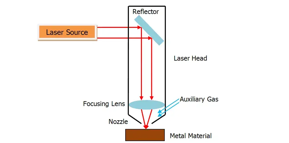
Fig. 3 principle of laser cutting
(2) Classification of laser cutting
Laser cutting can be categorized into four main types: laser vaporization cutting, laser melting cutting, laser oxygen cutting, and laser scribing with controlled fracture.
1) Laser vaporization cutting
In this process, a high-energy-density laser beam rapidly heats the workpiece, causing the material temperature to swiftly reach its boiling point. This results in material vaporization, forming a high-speed vapor jet. As the vapor is ejected, it simultaneously creates a kerf in the material.
Due to the typically high vaporization heat of materials, laser vaporization cutting demands substantial power and power density. This method is primarily employed for cutting extremely thin metal sheets and non-metallic materials such as paper, textiles, wood, plastics, and rubber.
2) Laser melting cutting
Laser melting cutting involves using laser heat to melt the metal material. A non-oxidizing gas (such as Ar, He, or N2) is then blown through a nozzle coaxial with the beam. The high-pressure gas stream expels the molten metal, creating a kerf.
This technique requires only about 1/10 of the energy needed for vaporization cutting, as it doesn’t necessitate complete material vaporization. Laser melting cutting is particularly effective for cutting materials that resist oxidation or active metals, including stainless steel, titanium, aluminum, and their alloys.
The efficiency and precision of laser melting cutting make it a preferred method in many industrial applications, especially where clean cuts and minimal heat-affected zones are crucial.
3) Laser oxygen cutting
Laser oxygen cutting combines the precision of laser technology with the exothermic reaction of oxygen cutting. This process utilizes a laser beam as the preheating source and oxygen as the cutting gas, creating a synergistic effect that enhances cutting efficiency and quality.
The mechanism operates on two primary fronts:
- Oxidation Reaction: The high-pressure oxygen stream interacts with the heated metal surface, initiating an exothermic oxidation reaction. This reaction releases a substantial amount of additional heat, further intensifying the cutting process.
- Material Removal: The combination of laser heating and oxidation produces molten metal and oxides. The high-velocity oxygen jet then expels this molten material from the kerf, creating a clean, narrow cut.
Due to the significant heat contribution from the oxidation reaction, laser oxygen cutting requires only about 50% of the laser energy needed for pure fusion cutting. This energy efficiency translates to considerably higher cutting speeds compared to laser vaporization or fusion cutting methods.
Laser oxygen cutting is particularly effective for materials with high oxygen affinity, such as:
- Carbon steels
- Low-alloy steels
- Certain grades of heat-treated steels
However, it is less suitable for materials that form refractory oxides or have low oxidation tendencies, such as stainless steels, titanium, aluminum, and their alloys. For these materials, other laser cutting techniques like fusion cutting with inert gas assist are more appropriate.
4) Laser scribing and controlled fracture
Laser scribing is a precision material processing technique that utilizes high-energy density lasers to create controlled, shallow grooves on the surface of brittle materials. This process involves the following steps:
- A focused laser beam, typically from a Q-switched or CO2 laser, scans the material surface.
- The intense localized heating causes rapid vaporization, creating a narrow, shallow groove.
- After scribing, controlled pressure is applied to the material.
- The brittle material fractures along the scribed line, resulting in a clean, precise break.
Controlled fracture, a related technique, leverages the steep temperature gradients generated during laser scribing to induce localized thermal stresses in brittle materials. This method:
- Creates a highly localized heat-affected zone along the scribed line.
- Generates thermal stresses due to rapid heating and cooling cycles.
- Exploits these stresses to propagate a crack along the desired path.
- Results in a controlled break with minimal material loss and high edge quality.
Both laser scribing and controlled fracture are particularly valuable for processing brittle materials such as glass, ceramics, and certain semiconductors, offering advantages in precision, speed, and reduced material waste compared to traditional cutting methods.
2.2 Characteristics of laser cutting
Compared with other thermal cutting methods, laser cutting is characterized by fast cutting speed and high quality.
It can be summarized as follows.
(1) Superior Cutting Quality
Laser cutting achieves exceptional cutting quality due to its small focal spot, high energy density, and rapid cutting speeds. This advanced technique offers several key advantages:
① Precision Kerf: The laser-cut kerf is exceptionally thin and narrow, with parallel sides perpendicular to the material surface. This precision allows for dimensional accuracies of cut parts reaching ±0.05mm (±0.002 inches), surpassing many traditional cutting methods.
② Immaculate Surface Finish: The cutting surface exhibits a clean and aesthetically pleasing appearance. Surface roughness is minimized to only a few tens of microns (typically 10-50 μm Ra), often eliminating the need for secondary finishing operations. In many cases, laser-cut parts can be used directly without additional mechanical processing, streamlining production workflows.
③ Minimal Heat Affected Zone (HAZ): The laser cutting process generates an extremely narrow heat affected zone. This localized heat input results in:
- Negligible alteration of material properties adjacent to the cut edge
- Minimal workpiece deformation, maintaining high overall accuracy
- Excellent kerf geometry, characterized by a consistent, rectangular cross-section along the cut path
The combination of these factors – precision, surface quality, and minimal thermal impact – makes laser cutting an ideal choice for applications requiring high-accuracy components, especially in industries such as aerospace, medical device manufacturing, and precision engineering.
See table 1 for the comparison of laser cutting, oxyacetylene cutting and plasma cutting methods.
The cutting material is 6.2mm thick low carbon steel plate.
Table 1 comparison of laser cutting, oxyacetylene cutting and plasma cutting
| Cutting method | Slit width / mm | Width of heat affected zone / mm | Slit shape | Cutting speed | quipment cost |
| Laser cut | 0.2~0.3 | 0.04~0.06 | parallel | Fast | High |
| Oxyacetylene cutting | 0.9~1.2 | 0.6~1.2 | Relatively parallel | slow | Low |
| Plasma cutting | 3.0~4.0 | 0.5~1.0 | Molded and inclined | Fast | Middle |
(2) High cutting efficiency
Laser cutting machines excel in productivity due to their unique transmission characteristics and advanced control systems. These systems typically incorporate multiple CNC (Computer Numerical Control) worktables, enabling fully automated and precisely controlled cutting processes.
The cutting operation is remarkably versatile and efficient. By simply modifying the CNC program, operators can swiftly transition between cutting parts with diverse geometries. This flexibility extends to both 2D and 3D cutting applications, accommodating a wide range of manufacturing requirements.
Key advantages of laser cutting efficiency include:
- Rapid setup times: Minimal tooling changes between jobs
- High-speed cutting: Laser beams move at velocities up to 20-30 m/min for thin materials
- Multi-axis capability: 5-axis systems allow complex 3D cuts in a single setup
- Automatic nesting: Software optimizes material utilization, reducing waste
- Continuous operation: Some systems feature automatic material loading/unloading for extended runtime
These features combine to significantly reduce cycle times, increase throughput, and enhance overall manufacturing productivity compared to traditional cutting methods.
(3) Fast cutting speed
A high-power laser system, typically utilizing a 1200 W source, can achieve remarkably high cutting speeds for various materials. When processing 2 mm thick low carbon steel plates, cutting speeds of up to 15,000 mm/min (590 in/min) are attainable, showcasing the efficiency of laser technology in metalworking.
The versatility of laser cutting extends to non-metallic materials as well. For instance, when cutting 5 mm thick polypropylene resin sheets, speeds can also reach 15,000 mm/min, demonstrating the system’s adaptability across different material types and thicknesses.
One of the key advantages of laser cutting is its non-contact nature, eliminating the need for mechanical clamping or fixturing of workpieces. This feature not only reduces tooling costs and simplifies setup but also significantly decreases auxiliary time for material loading and unloading. The absence of physical contact also minimizes the risk of workpiece deformation, particularly beneficial for thin or delicate materials.
Furthermore, the precision and speed of laser cutting contribute to reduced material waste and improved part consistency, enhancing overall manufacturing efficiency. The technology’s ability to perform complex cuts with minimal heat-affected zones makes it ideal for both prototyping and high-volume production scenarios in industries ranging from automotive to electronics manufacturing.
(4) Non-contact cutting
Laser cutting operates without physical contact between the cutting mechanism and the workpiece, eliminating tool wear and extending equipment longevity. This non-contact nature allows for precise cuts with minimal thermal distortion, particularly beneficial for heat-sensitive materials.
The versatility of laser cutting is unparalleled; processing diverse part geometries requires only adjustments to laser parameters such as power, frequency, and focal length. This flexibility significantly reduces setup time and enhances production efficiency compared to traditional cutting methods that necessitate tool changes.
Moreover, laser cutting offers several environmental and ergonomic advantages:
- Low noise emission, typically below 70 dB, enhancing workplace comfort
- Minimal vibration, ensuring high precision and reducing operator fatigue
- Near-zero pollution, as the process produces no chips and minimal fumes when properly ventilated
These characteristics make laser cutting an ideal choice for clean room environments and industries with strict quality and environmental standards, such as medical device manufacturing and aerospace applications.

