Flame Cutting vs Plasma Cutting: What’s the Difference?
When it comes to metal cutting, the choice between flame cutting and plasma cutting can significantly impact the efficiency and…
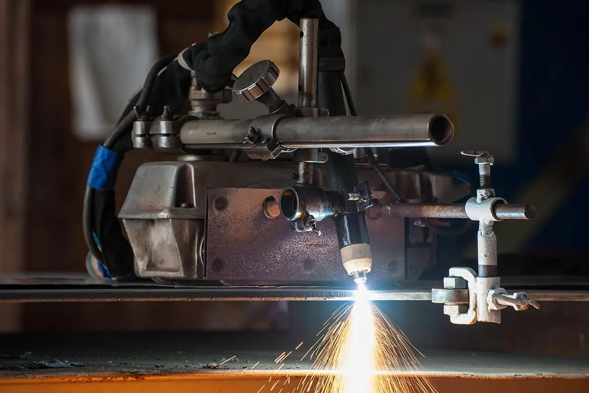
The plasma cutting machine uses compressed air as the working gas, and a high-temperature, high-speed plasma arc as the heat source to partially melt (and evaporate) the metal being cut. Simultaneously, the melted metal is blown away by a high-speed airflow, forming a narrow cutting seam.
Plasma cutting machines can be used to cut various metal materials such as stainless steel, aluminum, copper, cast iron, carbon steel, etc.
The plasma cutting machine not only has a fast cutting speed, narrow cutting seam, smooth cutting edge, small heat-affected zone, low workpiece deformation, simple operation, but also has significant energy-saving effects.
The plasma cutting machine is suitable for cutting, hole opening, patching, beveling, and other cutting processes in the manufacture, installation, and maintenance of various machinery and metal structures.

(1) Plasma Cutting Machine Cutting Current
The current size is related to the material and thickness of the cut piece. The cutting current increases with the thickness of the cut piece.
(2) Cutting Speed
The cutting speed depends on the thickness of the material to be cut and the cutting current. The speed of cutting significantly impacts the quality of the cut. If the speed is too fast, the plasma arc will not have enough time to melt the metal.
(3) Nozzle Height
The height of the nozzle from the piece being cut is related to the torch structure, generally 2-4mm from the metal surface.
(4) Working Gas
The development of plasma cutting now allows for the use of working gas (working gas is the conductive medium of the plasma arc, the heat carrier, and also eliminates the molten metal in the cut). It significantly impacts the cutting characteristics of the plasma arc and the cutting quality and speed. Commonly used plasma arc working gases include argon, hydrogen, nitrogen, oxygen, air, steam, and certain mixed gases.
(5) Gas Flow Rate
It affects the degree of arc compression and the effect of blowing away molten metal. If the flow rate is too high, the arc tends to be unstable. If the airflow is too small, it cannot blow away the molten metal and may even burn the conductive nozzle.
Cutting Torch:
1) Plasma generator, conduction nozzle, conductive electrode, gas distributor, ceramics, nozzle.
2) Cutting gas – Compressed air is used as the cutting gas for air plasma arc cutting.
3) Selection specifications – These include cutting current, cutting speed, gas flow, and parameters.
The stability of the plasma cutting machine arc directly affects the cutting quality. Instability in the plasma arc can lead to uneven cut edges, accumulation of defects, and reduced lifespan of the control system’s related components, along with frequent replacement of the nozzle and electrodes. Below are some analyses of common phenomena and some solutions:
The primary interference source for the plasma CNC system is the power supply section. It generally uses a high-frequency arc starter to ignite the arc. The secondary voltage of the high-frequency transformer can reach 3000-6000V, with a pulse frequency of hundreds of kilohertz.
The resulting radiation interference and pollution (interference) to the power grid are substantial.
Additionally, the large current AC/DC contactors and various relays shutting off can also cause surge impacts on the power grid.
The typical plasma cutting machine can cause internal computer chaos when arcing, making normal cutting impossible. The earliest CNC cutting machines even required the user to start the arc first, then start the computer and run the CNC system program.
This not only complicated the operation, but also did not fully utilize the computer, severely affecting its lifespan. Therefore, suppressing the interference from the plasma power source and reducing pollution to the power grid is a primary concern. Specific measures include:
(1) Add a shielding cover to the high-frequency arc starter to reduce high-frequency radiation;
(2) Modify the control circuit of the plasma power supply.
The control power supply of the plasma cutting machine is directly drawn from the grid voltage at 220V, and the arc start/stop control line is directly drawn from the cutting machine to the CNC cabinet, along with the power system of the CNC.
In this way, the high-frequency interference caused by plasma arc start/stop and the electromagnetic interference caused by large current are directly introduced into the grid.
The measure is to add an isolation transformer to the 220v strong electric control line, and at the same time, the control signal of arc start/stop is isolated by a relay into a relatively weak electric control line of AC 24v entering the CNC cabinet.
(3) Other wiring anti-interference measures
Add RC absorption circuits and varistor to the primary and secondary sides of the main transformer, parallel resistance-capacitance circuits on both ends of the current contactor and relay coil, and set up high-frequency bypass capacitors in the DC part. The purpose of all these measures is to suppress interference sources and reduce pollution to grid voltage.
The CNC device and servo unit of the CNC plasma arc cutting system are the core parts of the system, and their power supply is the main route for interference to enter.
Power supply interference is mainly generated through impedance coupling of the power supply line, and various high-power electrical equipment are the main sources of interference.
The power line of the CNC plasma arc cutting system. The cathode line of the torch and the plasma arc start/stop control line are hung together on the sliding bracket, equivalent to parallel wiring for several tens of meters, and the arc start/stop control line and the torch’s cathode line come from the plasma power supply.
The DC current on the cathode line of the torch is hundreds of amperes. Its electromagnetic field and the high-frequency signal of the high-frequency arc starter can cause electromagnetic interference to the power supply of the CNC device (CNC) and the servo unit through coupling.
Shielded cables with copper and aluminum as the shielding layer can effectively suppress high-frequency electromagnetic interference. After the shielding layer is grounded, it can also suppress the electrostatic induction of the changing electric field on the core wire.
Power supply filters are indispensable anti-interference components with beneficial interference suppression performance at high and low frequency bands. Points to note when using include:
a) The filter should be installed on a conductive metal surface, or connected to a grounding point through a braided grounding strap;
b) The location of the filter installation should be as close as possible to the power line entrance;
c) The input and output of the filter should preferably use shielded cables or twisted pair cables;
d) Avoid mutual coupling of input and output wires. It is strictly prohibited to bundle input and output wires together using a shielded cable.
When using shielded power transformers, the shielding layer should be connected to the AC neutral line of the primary winding. This can prevent interference from entering the secondary side of the power transformer.
Separating the shielded power transformers used by the numerical control device and the servo unit can also prevent mutual interference.
The numerical control device can be replaced with a purified AC stabilizer, or an interference suppressor made according to the principle of spectrum balancing method can be added, which will enhance its ability to resist power grid interference.
The high voltage and current changes within the high voltage wires can generate intense electric field fluctuations, forming electromagnetic wave interference, severely affecting nearby signal lines and low voltage control lines.
Keeping signal lines away from high voltage lines, as well as reasonably choosing shielded wires and twisted pair cables can avoid interference signals during transmission.
Using shielded cables can suppress interference entering the transmission lines via electromagnetic and electrostatic induction from stray electric floating magnetic fields. Moreover, the shielding layer uses the correct single-end grounding method.
The grounding process for CNC plasma cutting systems should be given enough attention, as its CNC part and servo units are moving parts on the track, and the strength of their interference is greatly related to the system’s grounding method.
(1) Separation of AC Ground and DC Ground
This avoids disturbances from AC power lines being transmitted to control devices due to resistance, ensuring the safety of internal devices in the control system, enhancing system reliability and stability, and reducing ground current interference from high current equipment.
(2) Floating the Logic Ground and Separating It from the Analog Ground
Floating refers to not having a conductive connection between the control device’s logic ground, analog ground, and the earth, using the floating “ground” as the system’s reference level. This largely suppresses external radiation interference from plasma arcs and electrostatic interference.
Because floating the logic ground increases the interference induction of the analog circuit, a good method is to connect the analog ground and logic ground separately to their respective busbars, and then connect the analog ground busbar to a grounding point through a capacitor. For analog values, this forms a DC floating ground and AC common ground system.
(3) Proper Grounding of the Cabinet
The CNC plasma arc cutting machine occupies a large area, so it is best to lay a separate grounding device. Moreover, the grounding device should be reliably connected to the machine tool’s guide rails, cabinet, and even the cable sliding bracket.
This provides a low-impedance leakage path for high-frequency interference voltages induced on the machine casing, eliminating the possibility of charge accumulation and voltage increase on the casing, making it safer for personnel and beneficial in suppressing interference surges.
If conditions permit, the power supply of the CNC device should use lighting electricity, as it is relatively clean; DC relay coils and rectifier diodes, AC relay coils and RC resistor-capacitor circuits should be used to suppress transient interference.
When the plasma cutter is working, if the working air pressure is significantly lower than what the manual specifies, it means the ejection speed of the plasma arc is weakened, and the input airflow is less than the prescribed value.
At this time, a high-energy, high-speed plasma arc cannot be formed, resulting in poor cut quality, incomplete cuts, and accumulation of slag at the cut. Possible reasons for insufficient air pressure include: insufficient air input from the compressor, too low pressure regulation of the cutting machine’s air regulation valve, oil contamination inside the solenoid valve, and blocked air passages.
The solution is to observe the output pressure display of the air compressor before use. If it does not meet the requirements, adjust the pressure or repair the air compressor. If the input air pressure has reached the requirement, check whether the adjustment of the air filter pressure reducing valve is correct; the pressure gauge display should meet the cutting requirements.
Otherwise, regular maintenance of the air filter pressure reducing valve should be performed to ensure the input air is dry and oil-free.
If the input air quality is poor, it will cause oil contamination inside the pressure reducing valve, making it difficult for the valve core to open and the valve port cannot open fully.
Additionally, if the nozzle pressure of the cutting torch is too low, the pressure reducing valve needs to be replaced; a reduced cross-sectional area of the air passage will also cause low air pressure, so the air pipe should be replaced according to the manual’s instructions.
If the input air pressure significantly exceeds 0.45MPa, then after forming the ion arc, the excessive airflow will disperse the concentrated arc column, causing the arc column energy to disperse and weakening the cutting strength of the plasma arc.
Causes of overpressure include improper air input regulation, excessively high adjustment of the air filter pressure regulator, or a failure of the air filter pressure regulator.
The solution is to check whether the air compressor pressure is adjusted appropriately, and whether the pressure of the air compressor and air filter pressure regulator is off balance.
After starting the machine, if there is no change in pressure gauge when rotating the air filter pressure regulator adjustment switch, it indicates that the air filter pressure regulator has failed and needs to be replaced.
Improper installation of the nozzle, such as not tightening the thread, improper adjustment of the equipment’s gears, not introducing flowing cooling water as required when using a water-cooled torch, and frequent arcing, can all cause premature nozzle damage.
The solution is to correctly adjust the equipment’s gears according to the technical requirements of the cutting workpiece, check whether the torch nozzle is firmly installed, and start circulating cooling water in advance for nozzles that require cooling water.
During cutting, adjust the distance between the torch and the workpiece based on the thickness of the workpiece.
Large electrical facilities in the operating site of the plasma cutter, as well as faults in the main circuit components within the cutter, can cause low input AC voltage. The solution is to check whether the power grid connected to the plasma cutter has sufficient load-bearing capacity and whether the power cord specification meets the requirements.
The installation site of the plasma cutter should be away from large electrical equipment and places frequently affected by electrical interference. During use, regularly clean the dust inside the cutter and dirt on the components, and check for wire aging.
Grounding is an essential preparation before cutting. Not using dedicated grounding tools, insulation on the workpiece surface, and severe aging of the ground wire due to long-term use can all cause poor contact between the ground wire and the workpiece.
The solution is to use dedicated grounding tools and check for insulating materials that may affect the contact between the ground wire and the workpiece surface. Avoid using aged ground wires.
When the plasma cutter is working, it first needs to ignite the plasma arc. This is done by a high-frequency oscillator stimulating the gas between the electrode and the inner wall of the nozzle, causing high-frequency discharge, which ionizes the gas locally to form a small arc.
This small arc, affected by compressed air, is sprayed out of the nozzle to ignite the plasma arc, which is the main task of the spark generator.
Normally, the operation time of the spark generator is only 0.5-1s. The inability to automatically extinguish the arc is generally due to the misalignment of the control circuit board components, and the discharge electrode gap of the spark generator is not suitable.
The solution: Regularly check the discharge electrode of the spark generator, keep its surface flat, adjust the gap between the discharge electrodes of the spark generator (0.8-1.2mm) in a timely manner, and replace the control board if necessary.
In addition to the above reasons, slow cutting speed, the verticality of the cutting torch to the workpiece during cutting, and the operator’s familiarity with the plasma cutter and operational level, all affect the stability of the plasma arc. Users should pay attention to these aspects!
Inspect the high-frequency pilot arc circuit. First, check the 110VAC supply and observe whether there are discharge sparks between G1 and G2. If not, it’s usually caused by an issue with the 110VAC supply or moisture absorption by the bakelite board holding G1 and G2, which prevents discharge and high voltage generation.
Dry the bakelite board with an electric blower and restore the 110VAC supply. If the pilot arc is still absent, check the high-frequency pilot arc wire.
Due to the skin effect of high frequency, the wire may not have good contact with the conductive ring inside the nozzle, or it might be short-circuited with the cooling water due to the sealing ring.
Disassembling the cutting torch, tightening the high-frequency wire or replacing the sealing ring usually resolves the issue.
When a high-frequency spark is observed, first check whether there is a 400VDC open circuit voltage. If not, check whether the three-phase power supply is missing a phase. Then, inspect the high-power SCR and trigger circuit board inside the power box.
If the power supply is normal, open the PLC control box and check the PLC’s input and output signals. Inputs include cooling water and cutting water flow signals, and nitrogen and oxygen pressure signals.
If there are no cooling water or cutting water flow signals, replace the cooling water pump and cutting water pump.
If there are no nitrogen or oxygen pressure signals, inspect the nitrogen and oxygen sources and check for leaks in the piping.
If all startup conditions are met, then check the cutting torch. If the sealing ring inside the electrode rod or on the nozzle is damaged, water will seep into the cavity between the electrode and nozzle, causing a short circuit between the DC power source and the nozzle, preventing a return circuit with the workpiece. Replacing the sealing ring and reassembling the cutting torch should resolve the issue.
This is characterized by an inability to pierce the workpiece, excessive slag, or uneven kerf. It’s usually caused by insufficient compression of the main arc, which results in a thicker arc column and inadequate penetrating power.
The main reasons are insufficient cutting gas pressure or leaks in the cutting gas pipeline.
Check the combined solenoid valve controlling the cutting gas, the combination switch, and the gas pipe. If you are using imitation nozzles, incorrect parameters can cause air flow disruption between the electrode and nozzle and lead to this issue.
During the operation of the plasma cutting machine, the plasma arc is first ignited. The high-frequency oscillator excites the gas between the electrode and the nozzle’s inner wall, causing high-frequency discharge, which partially ionizes the gas to form a small arc.
This small arc, propelled by compressed air, is ejected from the nozzle to ignite the plasma arc, which is the primary task of the spark generator.
Under normal circumstances, the operation time of the spark generator is only 0.5 to 1 second. The inability to automatically extinguish the arc is generally due to a misalignment of the components on the control circuit board, or the discharge electrode gap in the spark generator is inappropriate.
Regularly check the spark generator’s discharge electrode, keep its surface smooth, adjust the discharge electrode gap of the spark generator in time (0.8 to 1.2mm), and replace the control board if necessary.
Grounding is an indispensable preparation before cutting. Not using dedicated grounding tools, the presence of insulators on the workpiece’s surface, and the severe aging of the ground wire from long-term use can all lead to poor contact between the ground wire and the workpiece.
You should use specialized grounding tools, check for any insulating materials that might affect the contact between the ground wire and the workpiece’s surface, and avoid using aged ground wires.
Problem Description:
A plasma cutting machine is used to cut steel plates. The X and Y axes are stepper motors, with a transmission method of synchronous belt plus slider guide rail, and the end of the cutting torch head is a plasma generator.
The current issue is that during the machining process of the plasma cutting machine, at the moment when the plasma generator starts to arc, the X-axis will deviate to the left by several millimeters.
Cause Analysis:
When the power of the plasma generator is turned off, and the plasma cutting machine operates as usual, the software executes the arc-start operation and the X-axis does not deviate. This indicates that there is no problem with the plasma software and control card.
Solution:
The plasma power supply has a significant interference with the external environment, especially at the moment of arc initiation and piercing the steel plate. The solution is to ground the parts that may be affected by interference during machining.
(1) Ground the plasma power supply casing
(2) Connect a filter to the voltage input end of the plasma power supply to prevent interference with the external power supply circuit
(3) Ground the computer host casing. Ideally, the ground wire should be connected to the bolt at the connection part between the adapter cable and the control card
(4) Ground the plasma cutting machine casing
(5) Ground the power supply switch of the adapter board
Problem Description:
Cutting steel plates, X and Y axes are stepper motors, and the end of the cutting torch head is a plasma generator. Problem: When the plasma cutting machine is machining a square, the X-axis of the plasma cutting is normal, but when it moves to the Y-axis, it stops cutting due to arc interruption.
Cause Analysis:
Further testing during circular machining shows that it stops directly after arcing and cannot operate normally. When the power of the plasma generator is turned off, the plasma cutting machine can operate normally; this indicates that there is no problem with the plasma software and control card, and the Y-axis is being interfered with.
Solution:
(1) Ground the plasma power supply casing
(2) Connect a filter to the voltage input end of the plasma power supply to prevent interference with the external power supply circuit
(3) Ground the computer host casing. Ideally, the ground wire should be connected to the bolt at the connection part between the adapter cable and the control card
(4) Ground the plasma cutting machine casing
(5) Ground the power supply switch of the adapter board
Problem Description:
The control system experiences screen flashing, rebooting, and freezing during plasma cutting. These issues cease when the plasma power is turned off.
Solution:
(1) Ground the plasma power supply casing.
(2) Connect a filter to the voltage input end of the plasma power supply to prevent interference with the external power supply circuit.
(3) Ground the computer host casing. It is best to connect the ground wire to the bolt at the junction of the adapter wire and the control card.
(4) Ground the plasma cutting machine casing.
(5) Ground the switch power supply of the adapter board.
(6) The control system hardware has malfunctioned.