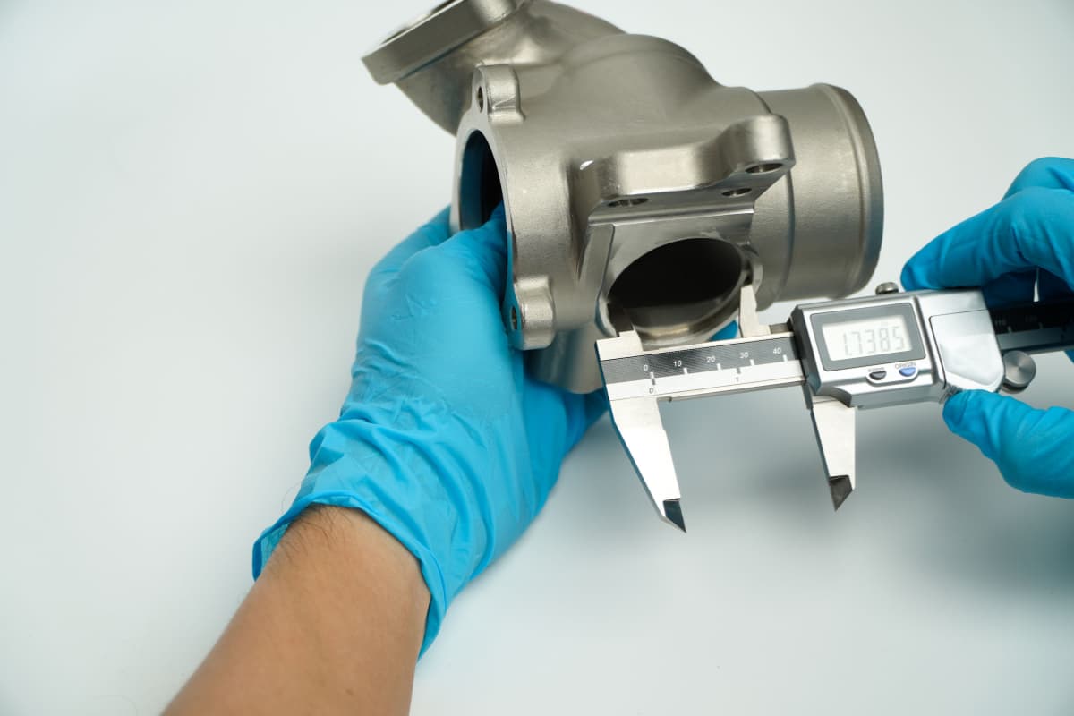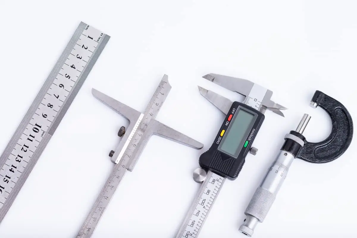
I. Precision measuring tools and instruments commonly used by lathe operators
Precision measurement work should be carried out under constant temperature conditions. The temperature of the constant temperature room is usually controlled at (20±1)°C, with humidity less than 65%. The room should be clean, dust-free, well-lit, equipped with precision measuring instruments, large and small precision plates, and common measuring tools and instruments.
In mechanical manufacturing, measuring instruments used to measure workpiece dimensions include measuring tools, measuring instruments, and measuring devices. Any measuring tools, measuring instruments (meters), and measuring devices that can directly or indirectly measure the value of the measured object are collectively referred to as measuring instruments.
Measuring tools refer to measuring instruments that reproduce values in a fixed form. Measuring instruments (meters) refer to measuring instruments that convert the measured quantity into directly observable indication values or equivalent information.
The following will introduce the measurement principles and methods of some precision measuring tools and instruments commonly used in factories.
1. Dial indicator
A dial indicator is a pointer-type measuring instrument widely used in turning operations. It can be used to measure the shape and position errors of workpieces, and can also be used to measure workpiece dimensions by comparison method. There are two types of dial indicators: dial type and lever type.
(1) Dial type indicator (also known as dial gauge)
The dial type indicator and its construction principle are shown in Figure 1. It uses the transmission between gears and racks to convert the micro linear displacement of the measuring rod into the angular displacement of the pointer. Its scale values come in 0.001mm and 0.002mm.
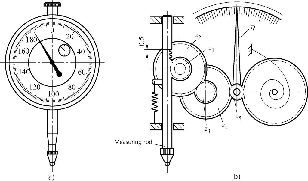
a) External view
b) Construction principle diagram
The transmission system of the dial type indicator consists of a rack, gear transmission, and two pairs of gears. The rack pitch on the measuring rod is P=0.5mm, z1 =40, z2 =120, z3 =16, z4 =160, z5 =12. When the measuring rod moves linearly by a distance a=0.2mm, the number of rotations n of the long pointer is

The dial is divided into 200 divisions, and the value b represented by each division is
b=0.2mm/200=0.001mm
The purpose of the hairspring is to eliminate errors caused by the meshing clearance of gear transmission, and the measuring force is generated by a tension spring.
(2) Lever dial indicator
The lever dial indicator with a scale value of 0.002mm and its construction principle are shown in Figure 2. When the spherical measuring rod 7 swings to the left, the rocker arm 6 pushes the cylindrical pin C on the sector gear 5, causing the sector gear 5 to rotate counterclockwise around axis B, at which point the cylindrical pin D disengages from the rocker arm 6.
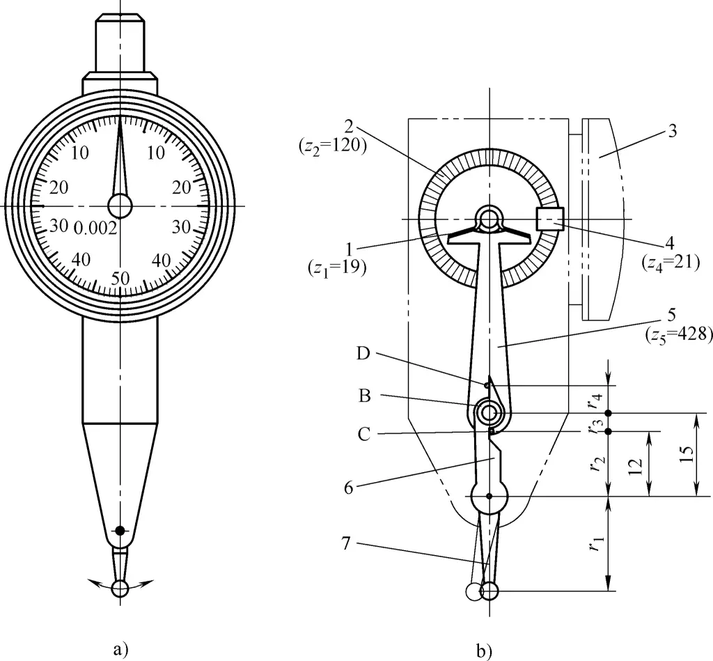
a) External view
b) Principle diagram
1, 4—Small gears
2—Face gear
3—Pointer
5—Sector gear
6—Rocker arm
7—Spherical measuring rod
When the spherical measuring rod 7 swings to the right, the rocker arm 6 pushes the cylindrical pin D on the sector gear 5, also causing the sector gear 5 to rotate counterclockwise around axis B, at which point the cylindrical pin C disengages from the rocker arm 6.
In this way, regardless of whether the spherical measuring rod 7 swings left or right, the sector gear 5 always rotates counterclockwise around axis B. The sector gear 5 then drives the small gear 1 and the coaxial face gear 2, which through the small gear 4 causes the pointer 3 to indicate the value on the dial.
As shown in Figure 2b, given r1 =16.39mm, r2 =12mm, r3 =3mm, r4 =5mm, z1 =19, z2 =120, z4 =21, z5 =428. When the spherical measuring rod 7 moves 0.2mm to the left, the number of rotations n of pointer 3 is

When the spherical measuring rod 7 moves 0.2mm to the right, the number of rotations n of pointer 3 is

The dial is divided into 100 divisions, and the measurement value b represented by each division is
b=0.2mm/100=0.002mm
Skill master’s experience:
1) When using a dial type indicator for measurement, the axis of the indicator’s measuring rod should be perpendicular to the surface of the measured workpiece, otherwise measurement errors will occur. Figure 3 shows the correct measurement method where the angle between the measuring rod axis and the measured surface of the workpiece is correct.

a) Correct measurement method
b) Incorrect measurement method
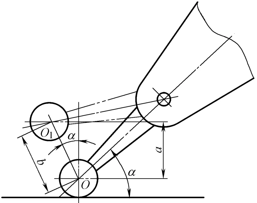
2) When using a lever dial indicator, the smaller the angle between the measuring rod axis and the measured workpiece surface, the smaller the error. If the angle α cannot be adjusted to be small due to measurement requirements (when α>15°), the measurement results should be corrected.
As shown in Figure 4, when the plane rises by a distance a, the lever dial indicator swings by a distance b, which is the reading of the lever dial indicator. Because b>a, the indicated reading increases.
a=bcosα
Where
a – Distance the plane rises (mm);
b – Distance the lever dial indicator swings (mm);
α – Angle between the lever dial indicator measuring rod axis and the measured surface (°).
3) When using a dial indicator, it should be securely fixed to avoid vibration; the measuring head should not suddenly contact the measured object; adjust the indicator properly; do not exceed the measurement range of the dial indicator; do not measure workpieces with relatively rough surfaces.
4) Prevent water, oil, or other liquids from entering the indicator or getting on the measuring rod, as this can easily cause measurement errors.
5) Dial indicators should not be placed or used near magnetic fields to prevent loss of accuracy due to magnetization of the components.
2. Lever micrometer
The lever micrometer (Figure 5) is a precision measuring tool composed of the thimble part of a micrometer and a lever gear transmission magnification part. It has high precision and is mainly used for precise measurements. It has scale values of 0.001mm and 0.002mm. It can be used for both comparative and absolute measurements.
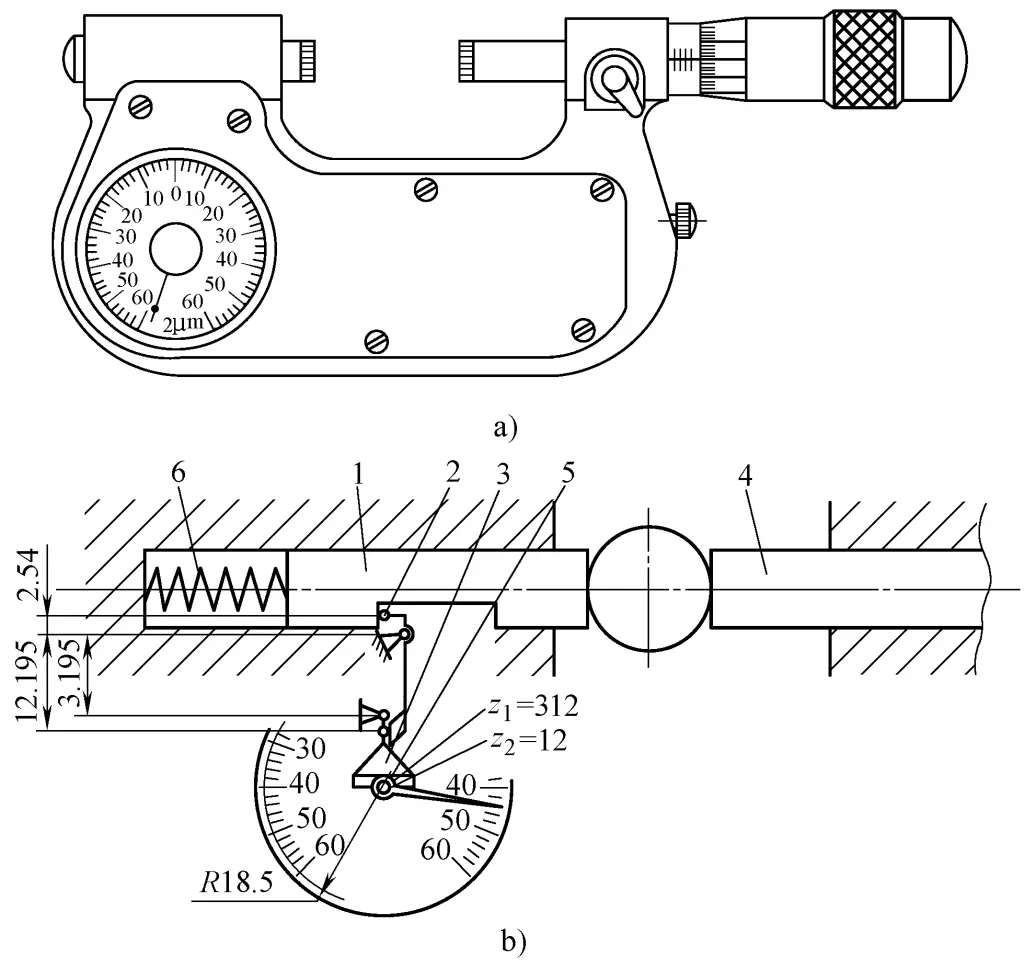
a) External view
b) Principle diagram
1—Movable anvil
2—Lever
3—Sector gear
4—Movable measuring rod
5—Small gear
6—Compression spring
The working principle of the lever micrometer is shown in Figure 5b. When the movable anvil 1 moves, it drives the pointer to rotate through the lever 2, sector gear 3, and small gear 5 mounted on the same axis, indicating the movement of the movable anvil 1 on the dial. The hairspring eliminates the clearance in the transmission chain, and the measuring force is generated by the compression spring 6.
If the length of the lever’s short arm r1 =2.54mm, the length of the lever’s long arm r2 =12.195mm, the pitch circle radius of the small gear r3 =3.195mm, the pointer length R=18.5mm, the number of teeth on the small gear z2 =12, the number of teeth on the sector gear z1 =312, the transmission magnification ratio k is

That is, when the movable anvil 1 moves a=0.002mm, the pointer rotates one division with a scale value b of
b≈ak=0.002mm×732=1.446mm
Skill master’s experience:
1) When using a lever micrometer for relative measurement, gauge blocks must be used to adjust the lever micrometer according to the size of the measured workpiece. When reading, the error of the gauge block or gauge block set should be considered.
2) When measuring a workpiece with a lever micrometer, first press the retraction button to allow the workpiece to gently contact the measuring rod anvil face, without forcing it.
3) Before measuring the workpiece, it should be placed on a cast iron surface plate to reach room temperature; during measurement, operation should be skilled and quick to prevent temperature changes from affecting measurement accuracy.
4) When measuring the diameter of a workpiece, the reading should be taken at the turning point of the pointer.
3. Lever snap gauge
The lever snap gauge is a measuring tool made using the lever gear transmission magnification principle, with scale values of 0.002mm and 0.005mm. It can be used with gauge blocks for relative measurement of workpieces, and can also measure the shape errors of workpieces.
The working principle of the lever snap gauge is shown in Figure 1-76a. When the movable anvil 1 moves, it drives the pointer 7 to rotate through the lever 2, sector gear 3, and small gear 5 mounted on the same axis, indicating the movement of the movable anvil 1 on the dial 8.
The hairspring 6 eliminates the clearance in the transmission chain, and the measuring force is generated by the spring 10. To reduce wear on the measuring surfaces and facilitate measurement, it is equipped with a retraction button 9. The external view of the lever snap gauge is shown in Figure 6b.
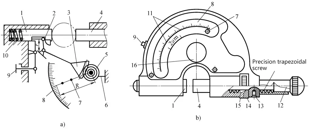
a) Working principle diagram
b) External view
1—Movable anvil
2—Lever
3—Sector gear
4—Adjustable anvil
5—Small gear
6—Hairspring
7—Pointer
8—Dial
9—Button
10—Spring
11—Tolerance indicator
12—Sleeve
13—Screw
14—Knurled nut
15—Disc spring
16—Cover
Before measuring, first loosen the sleeve 12, place the gauge block between the movable anvil 1 and the adjustable anvil 4, then turn the knurled nut 14 to align the pointer 7 with the zero position on the dial, and finally tighten the sleeve 12 to fix the adjustable anvil 4.
The disc spring 15 eliminates the clearance between the nut and the trapezoidal thread on the adjustable anvil, and the screw 13 prevents the adjustable anvil from rotating. Remove the cover 16 to adjust the tolerance indicator using a special wrench.
If the length of the lever 2 is r, the length of the pointer 7 is R, the number of teeth on the sector gear 3 is z1 , the number of teeth on the small gear 5 is z2 , when the movable anvil 1 moves a distance a, the distance b traveled by the pointer 7 is

Therefore
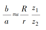
Where b/a is the magnification ratio, and let it equal k, then

The larger the radius R of the pointer 7, the more teeth z1 on the sector gear 3, the smaller the length r of the lever 2, and the fewer teeth z2 on the small gear 5, the greater the magnification ratio k.
4. Sine bar
A sine bar (also known as a sine ruler) is a measuring tool that uses the sine function principle for indirect measurement, as shown in Figure 7.
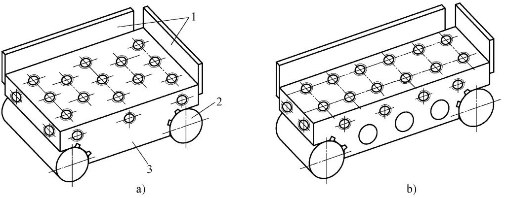
a) Wide type
b) Narrow type
1—End plate
2—Cylinder
3—Main body
The sine bar is mainly composed of a high-precision working plane and two precision cylinders of the same diameter. The axes of the two cylinders are parallel to each other, and the center line connecting them is parallel to the working surface. According to different uses, they are divided into wide type, narrow type, and type with center points.
The sine bar measures according to the principle of the sine function. When using, place gauge blocks or a set of gauge blocks with a size of h under one cylinder of the sine bar, so that the working plane of the sine bar forms an angle α with the surface plate. Compare this angle with the angle of the workpiece being inspected.
Skill master’s experience:
- The sine bar is a precision measuring tool, so it must be cleaned thoroughly before use.
- The surface roughness Ra value of the measured workpiece should be less than 1.6μm; the workpiece surface should not have burrs, dirt, and must not be magnetic.
- The sine bar should be handled gently, and it is strictly prohibited to hit or drag it to avoid wearing the cylinders and affecting accuracy.
- After using the sine bar, it should be cleaned thoroughly, coated with anti-rust oil, and stored in a special case.
- When placing the workpiece to be measured on the sine bar, use the front or side stop of the sine bar for positioning to ensure that the angle cross-section of the workpiece is in the vertical plane of the sine bar cylinder axis, otherwise it will lead to measurement errors.
5. Lever gear comparator
The division value of the lever gear comparator is 0.001mm, the measuring range is ±0.05mm, its range is smaller than a dial indicator, but the accuracy is higher than a dial indicator. The lever gear comparator is usually mounted on a special measuring stand for measurement, as shown in Figure 8.
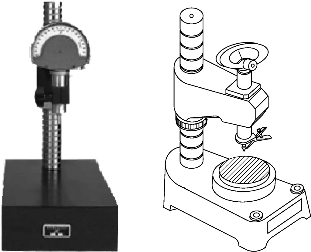
During measurement, the size of gauge blocks is used as a standard to measure the dimensions of precision workpieces using the comparison method, and it can also measure the shape and position errors of workpieces.
The lever gear comparator is shown in Figure 9. When the measuring rod 7 moves, it causes the sector gear 5 to rotate through lever 6, and the small gear 4 also rotates. The sector gear 3, which is coaxial with the small gear 4, transmits the motion to the small gear 2, and the pointer 1 indicates the corresponding reading on the dial.
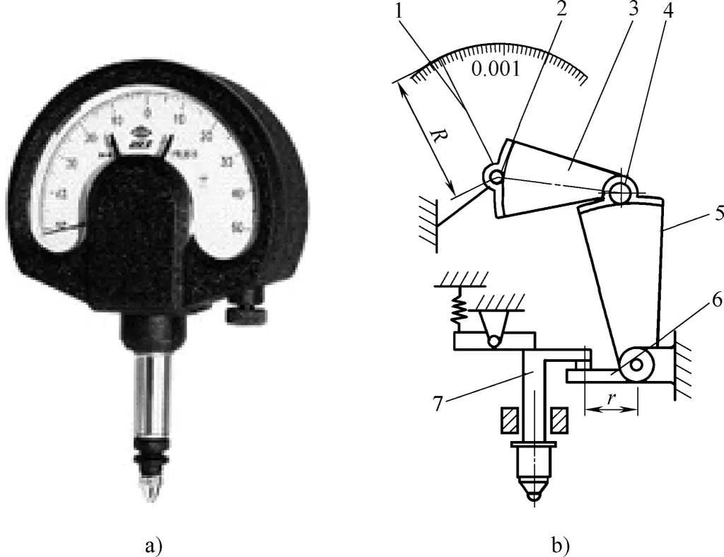
a) External view
b) Schematic diagram
1—Pointer
2, 4—Small gears
3, 5—Sector gears
6—Lever
7—Measuring rod
If the arm length of lever 6 is r, the length of pointer 1 is R, and the number of teeth of gears 2, 3, 4, 5 are z2 , z3 , z4 , z5 respectively. When the measuring rod 7 moves a distance a, the distance b that pointer 1 rotates is
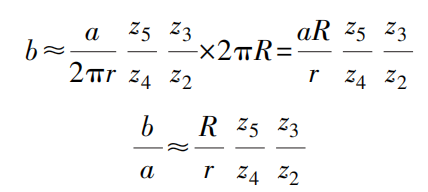
Where b/a is called the magnification ratio, and let it equal k, then

Given r=4.52mm, R=24.5mm, z2 =18, z3 =180, z4 =28, z5 =400, the magnification ratio k is

When the measuring rod 7 moves a distance a=0.001mm, the distance b that the pointer rotates one division is
b=ak=0.001mm×774=0.774mm
6. Torsion spring micrometer
The torsion spring micrometer uses a torsion spring as the transmission mechanism for size conversion and magnification. Its outstanding feature is its simple structure, large magnification factor, and no friction or clearance in the magnification mechanism, thus improving measurement accuracy and sensitivity. Its external view and schematic diagram are shown in Figure 10.
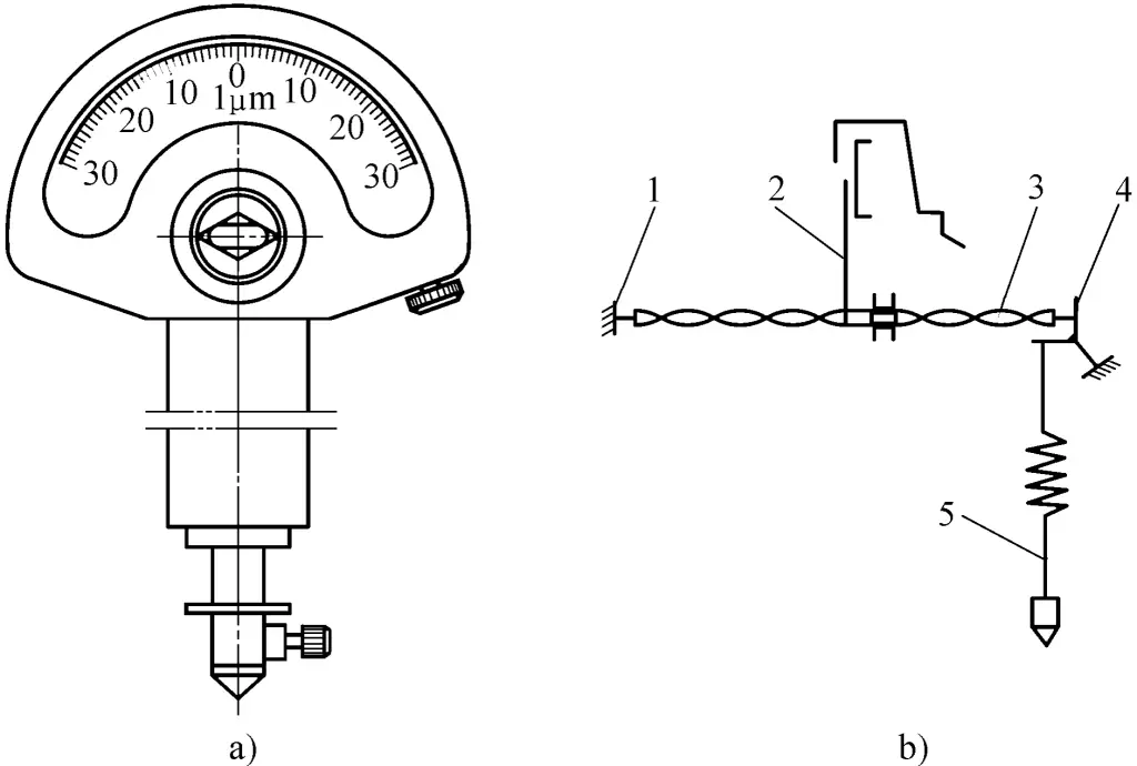
a) External view
b) Schematic diagram
1—Frame
2—Pointer
3—Torsion spring strip
4—Spring bridge
5—Measuring rod
The torsion spring strip 3 is a beryllium bronze metal strip with a rectangular cross-section (0.005mm × 0.1mm × 40mm), one end fixed to the frame 1 and the other end fixed to the spring bridge 4. A pointer 2 is installed in the center of the torsion spring. Half of the metal strip is twisted to the right from the center, and the other half is twisted to the left. When the measuring rod 5 has a small upward displacement, the upper end of the spring bridge 4 moves to the right, stretching the torsion spring strip 3, causing the glass fiber pointer 2 located at the center of the torsion spring strip to deflect at an angle, indicating the displacement of the measuring rod 5.
The measurement method of the torsion spring micrometer is the same as that of the lever gear comparator. Additionally, the head of the torsion spring micrometer can be mounted on a stand to perform various measurements on a platform. During measurement, the head should be perpendicular to the surface of the workpiece being measured.
Skill master’s experience:
1) The lever gear comparator and torsion spring micrometer should first be installed on a fixed measuring stand. Before measuring, adjust the measuring worktable of the measuring stand to make it perpendicular to the axis of the measuring rod of the lever gear comparator and torsion spring micrometer; then adjust the column of the measuring stand to make the measuring head lightly contact the gauge block or workpiece.
2) During the measurement process, try to use the central part of the dial scale as much as possible.
3) The structure of the torsion spring micrometer is fragile and the measuring range is small. Carefully adjust the contact distance between the measuring head and the workpiece; change the measuring head in a timely manner according to the shape of the workpiece.
4) The surface roughness Ra value of the measured workpiece should be less than 1.6μm; the workpiece surface should not have burrs or dirt. The workpiece should be placed on a cast iron surface plate and allowed to reach room temperature before measurement; during measurement, operation should be skilled and quick to prevent temperature changes from affecting measurement accuracy.
7. Gauge blocks
Gauge blocks are high-precision measuring tools whose working length is determined by the distance between two parallel measuring surfaces, mainly used for the transfer of length reference dimensions, as shown in Figure 11. Gauge blocks can also be used to verify measuring instruments, adjust the zero position of instruments in relative measurements, and adjust precision machine tools.
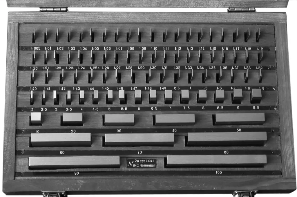
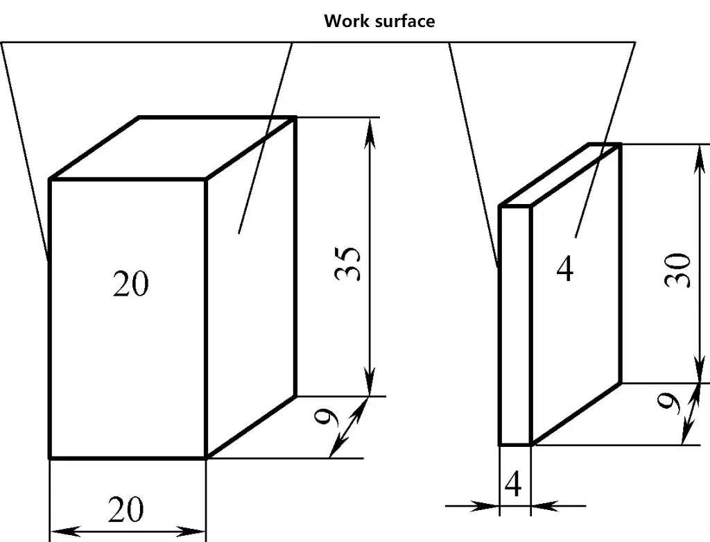
Gauge blocks are rectangular prisms with rectangular cross-sections made of chrome-manganese steel, nickel-chrome steel, or bearing steel. They have a pair of parallel, high-precision, low surface roughness measuring working surfaces. Each gauge block is marked with a nominal size, as shown in Figure 12.
The manufacturing precision of gauge blocks is divided into six grades: 00, 0, 1, 2, 3, and K, with 00 being the highest precision and 3 being the lowest, while K is the calibration grade.
The main basis for dividing gauge blocks into “grades” is their manufacturing precision, which depends on the limit deviation of the central length of the gauge block, the tolerance of length variation, and wringing ability. When used by grade, the nominal size marked on the gauge block is used directly, which is convenient but has manufacturing errors, resulting in less accurate measurement results.
Gauge blocks are divided into six classes according to their verification precision: 1, 2, 3, 4, 5, and 6, with 1 being the highest precision and 6 being the lowest. The main basis for dividing gauge blocks into “classes” is their verification precision, which depends on the limit deviation of the central length of the gauge block, the tolerance of plane parallelism, and wringing ability. When used by class, the actual size of the verified gauge block is used, resulting in higher measurement precision.
Gauge blocks are used in sets and can be combined to form various sizes. When the working surface of one gauge block slides along the working surface of another gauge block, they can adhere to each other with just a slight hand pressure. Therefore, multiple gauge blocks can be combined into a gauge block set as needed.
When combining gauge blocks to form a certain size, use the least number of gauge blocks to form the required size, generally not exceeding four blocks. When selecting gauge blocks, start from the last digit of the required combination size and select blocks that reduce the number of digits by one for each selection, and so on.
For example: To form a gauge block set of 38.935mm using a set of 83 gauge blocks, the selection method is as follows:
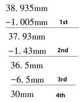
Skill master’s experience:
1) Gauge blocks are only allowed for verifying measuring instruments, performing precision measurements, and adjusting precision machine tools.
2) Before using gauge blocks, carefully inspect the appearance of the gauge blocks and the measured surface of the workpiece. Any magnetic workpieces should be demagnetized before using gauge blocks.
3) Before combining gauge block sets, clean the gauge blocks with non-acidic aviation gasoline, anhydrous ethanol, or pure benzene, wipe the gauge blocks clean with fine soft chamois, degreased cotton, linen, or silk, then use the parallel wringing method or cross wringing method for combination.
4) After use, promptly disassemble the gauge block set, clean and wipe them, apply anti-rust oil, and place them in their designated positions in the special case.
5) Regularly verify the gauge blocks and keep the verification certificate in the case.
8. Spirit level
A spirit level is a commonly used measuring tool for measuring small angles of inclination of a workpiece surface relative to the horizontal position. It is mainly used to measure straightness and perpendicularity errors and can be used when adjusting and installing equipment to horizontal or vertical positions.
(1) Frame spirit level
A frame spirit level is shown in Figure 13. The measuring surface of the frame has both a flat surface and a V-groove, with the V-groove facilitating measurement on cylindrical surfaces.
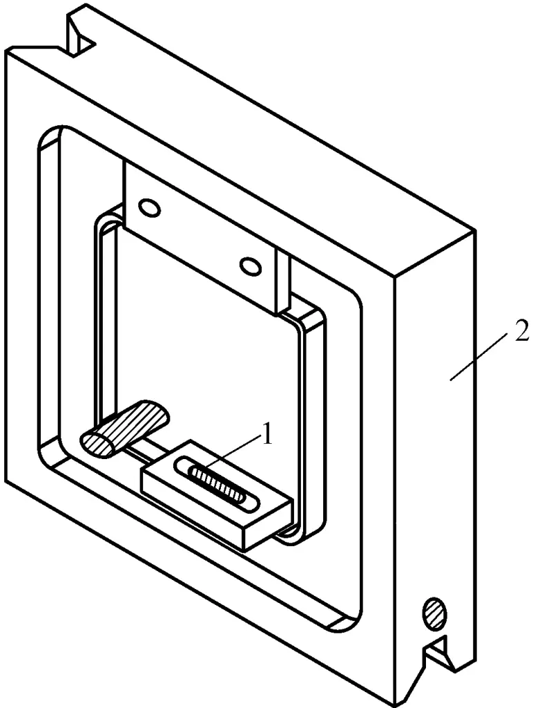
1—Main level vial
2—Main body
The level vial is a sealed glass tube with a certain radius of curvature, marked with graduations on the surface, filled with ether, and containing a bubble. The bubble always stays at the highest point inside the glass tube. If the spirit level is tilted at an angle, the bubble moves to the left or right, and the straightness or perpendicularity error can be calculated based on the distance it moves.
The working principle of the spirit level is shown in Figure 14. For a spirit level with a division value of 0.02mm/1000mm, the main level vial has a radius of curvature R=103132mm. When the plane is inclined by 0.02mm over a length of 1000mm, the inclination angle θ is
tanθ=0.02mm/1000mm=0.00002
θ=4”
The angle through which the bubble rotates is equal to the angle through which the plane rotates. The distance the bubble moves for 1 division is

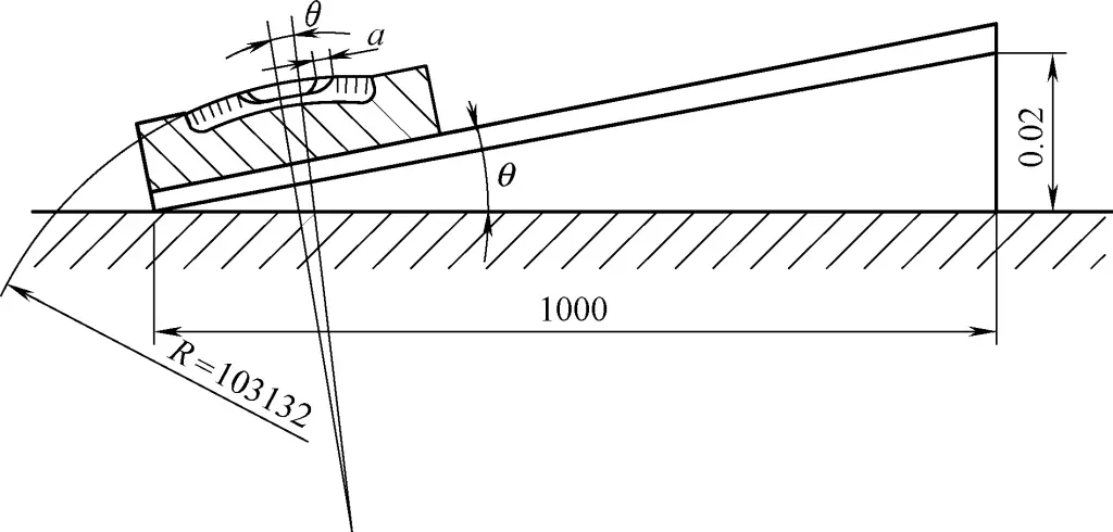
That is, for a spirit level with a division value of 0.002mm/1000mm, the distance between each graduation on the glass tube is 2mm. From this, we can see that the spirit level is a measuring instrument made using the principle of equal rotation angle and magnified radius of curvature.
(2) Coincidence spirit level
A coincidence spirit level is a small angle measuring instrument with relatively high measurement accuracy, large measurement range, and convenient portability, as shown in Figure 15. The bubble in the level vial 7 is imaged simultaneously at both half-edges through the coincidence prism 8 in the field of view of the sighting magnifier 1.
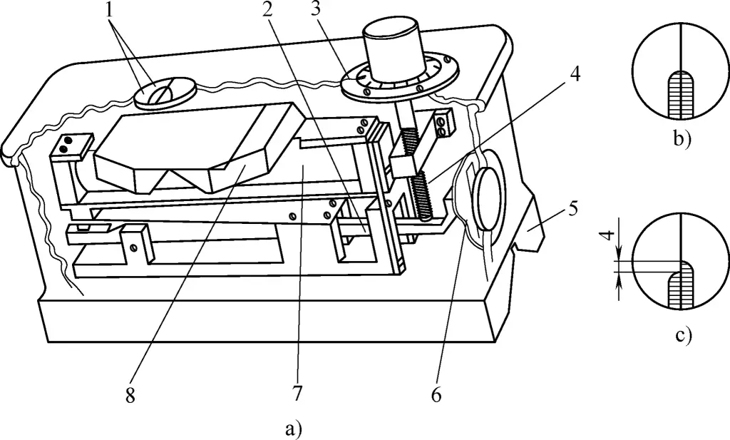
1—Sighting magnifier
2—Lever
3—Graduated dial
4—Micrometer screw
5—Base
6—Scale
7—Spirit level
8—Coincidence prism
When using, place the level on the workpiece being measured. When tilted at a certain angle, you can see through the sighting magnifier 1 that the two half-edges of the image come together with a misalignment. Turn the micrometer screw 4 by hand, using lever 2 to slightly rotate the spirit level 7 until the images of the bubble edges merge into a smooth semicircular head.
The integer part of the reading is read from scale 6, and the decimal part is read from the dial 3. For example, if the scale indicates 1mm and the dial has turned
16 divisions, the reading is 1.16mm, which means a height difference of 1.16mm per 1m length.
II. Common dimension measurement methods
The machining quality of parts includes machining accuracy and surface quality. Machining accuracy includes dimensional accuracy, shape accuracy, and position accuracy. Surface quality indicators include surface roughness, degree of surface work hardening, and the nature and magnitude of residual stress. Here we will mainly introduce dimensional accuracy and its inspection, as well as shape and position accuracy and their inspection.
Dimensional accuracy refers to the degree of conformity between the actual part dimensions and the ideal part dimensions, i.e., the degree of dimensional accuracy, which is controlled by dimensional tolerances (referred to as tolerances).
Higher tolerance grades have smaller tolerance values and higher precision; conversely, larger tolerance values result in lower precision. For parts with the same nominal size, the magnitude of the tolerance value determines the precision of the part. Smaller tolerance values indicate higher precision, while larger tolerance values indicate lower precision.
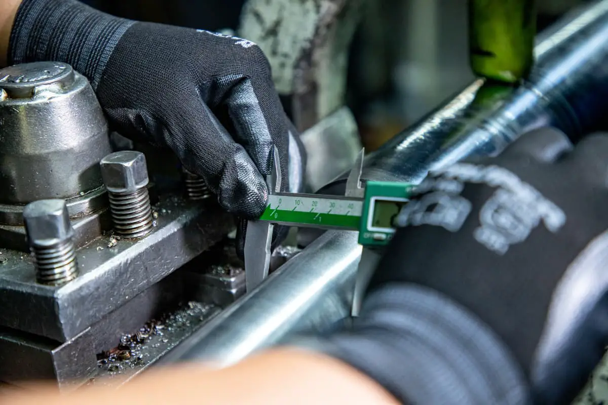
In the mechanical manufacturing industry, there are two main categories of instruments used to measure or inspect workpiece dimensions: measuring tools and measuring instruments (referred to as measuring devices). Measuring tools refer to simple measuring devices that can directly represent the unit limits of length, such as steel rules, vernier calipers, micrometers, gauge blocks, plug gauges, and snap gauges.
Measuring devices are instruments that magnify or subdivide length using mechanical, optical, pneumatic, or electrical principles, such as dial indicators, micrometers, torsion micrometers, and spirit levels. When using these instruments for inspection, if the measured dimension is between the upper and lower limit dimensions, the part is considered acceptable.
If the measured dimension is greater than the maximum material size, the part is unacceptable and requires further processing. If the measured dimension is smaller than the minimum material size, the part is scrapped.
1. Inspection of internal and external diameters, length, depth, and groove width
(1) Measurement of external diameter.
When measuring external diameters, vernier calipers and snap gauges are generally chosen for standard precision dimensions, while micrometers and other precision measuring tools are selected for higher precision requirements. Types of external micrometers are shown in Figure 16.
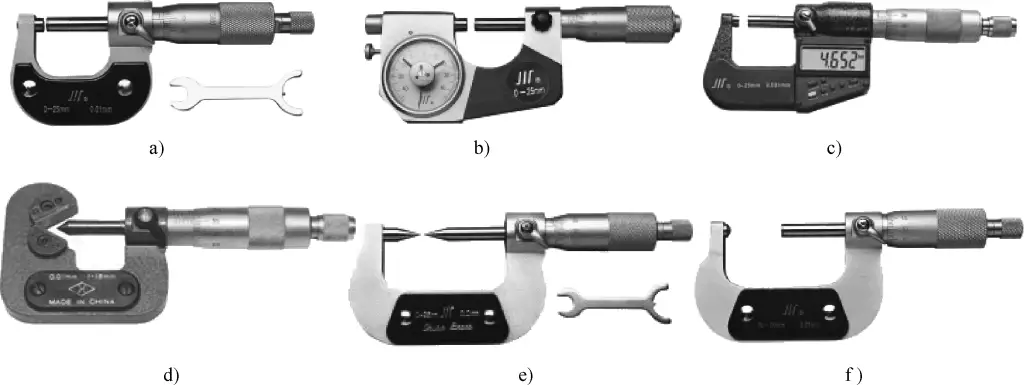
a) Standard external micrometer
b) Lever-type external micrometer
c) Digital external micrometer
d) Three-groove external micrometer
e) Point micrometer
f) Wall thickness micrometer
(2) Measurement of internal diameter.
When measuring hole diameters, appropriate measuring tools should be selected based on the size, quantity, and precision requirements of the workpiece. For lower precision requirements, steel rulers, inside calipers, plug gauges, or vernier calipers can be used. For higher precision requirements, internal micrometers, inside micrometers, or bore gauges can be used. Common internal diameter measuring tools are shown in Figure 17.
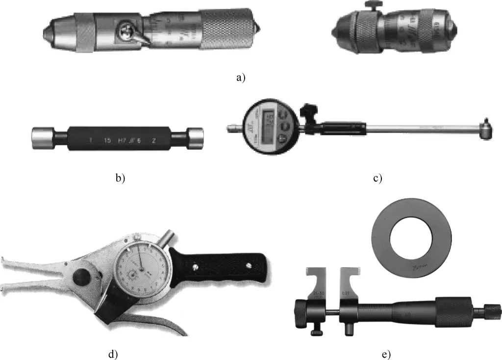
a) Internal micrometer
b) Smooth cylindrical plug gauge
c) Bore gauge
d) Internal snap gauge
e) Inside micrometer
(3) Measurement of length, depth, and groove width.
Length generally refers to the dimensions of external surfaces, such as the distance from a step face to a certain end face. If the dimensional accuracy requirements are not high, steel rulers, templates, vernier calipers, or vernier depth gauges can be used for measurement. Common measuring tools are shown in Figure 18. If higher dimensional accuracy is required, the workpiece can be placed on an inspection plate, and dial indicators or lever dial indicators and gauge blocks can be used for comparative measurement.
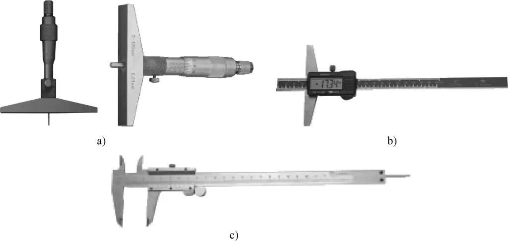
a) Depth micrometer
b) Vernier depth gauge
c) Vernier caliper
2. Methods for checking conical taper
(1) Checking taper using a universal bevel protractor.
For angular parts or conical surfaces with lower precision requirements, a universal bevel protractor can be used to check the taper, as shown in Figure 19.
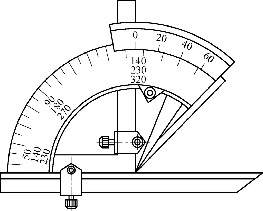
First, adjust the universal bevel protractor to the angle range to be measured. Align the protractor’s angle face with the workpiece’s end face (through the workpiece center), and make the steel ruler contact the workpiece’s inclined surface. Use the light transmission method to measure the angle.
Skill master’s experience:
Before measuring, remove burrs from the workpiece and keep the workpiece and measuring tool surfaces clean. The protractor’s measuring face must pass through the workpiece’s center symmetry plane, and the base surface must match the workpiece’s reference surface. When reading, first tighten the fixing screw on the universal bevel protractor, then move it away from the workpiece to prevent angle changes that could cause measurement errors.
(2) Checking taper and dimensions using a taper gauge.
First, use the coloring method to apply three thin, even lines of prepared red lead or blue ink along the workpiece’s generator line over its entire length. Then gently fit the gauge onto the workpiece and repeatedly align them. Note that the rotation range should be within half a turn.
Remove the gauge and observe the “printed” red lead traces on the workpiece’s tapered surface to judge the accuracy of the taper. Use the gauge’s go and no-go end lines to determine the conical dimensions, as shown in Figure 20.

(3) Checking taper using a sine bar.
During inspection, place the sine bar on a precision plate and the workpiece on the sine bar’s working table. Place a set of gauge blocks under one of the sine bar’s cylinders. The height of the gauge block set can be calculated based on the conical angle of the workpiece being measured.
Then use a dial indicator (or micrometer) to check the height of the two ends of the workpiece’s conical generator line. If the heights at both ends are equal, it indicates that the workpiece’s angle or taper is correct. If the heights at both ends are unequal, it indicates that the workpiece’s angle or taper has an error.
Sine bars have many applications and are commonly used to check workpiece angles and tapers.
Figure 21 shows how to measure a conical angle using a sine bar. First, calculate the gauge block set dimension h according to the nominal value α’ of the conical angle to be measured, forming a standard angle α.
h=Lsinα
Where
- L – Center distance between the two cylinders of the sine bar (mm);
- α – Nominal value of the workpiece’s conical angle (°).
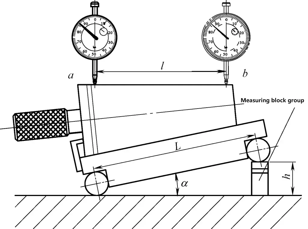
Place the sine bar on a plate with one cylinder in contact with the plate. Place a gauge block set with dimension h under the other cylinder, tilting the sine bar’s main working plane relative to the plate at a standard angle α.
After placing the conical workpiece, use a micrometer to measure points a and b on the upper generator line of the measured cone (the distance between points a and b is l). The readings at points a and b are r₀ and r₁ respectively. If r₀ ≠ r₁, it indicates that there is a taper error between the conical angle of the measured workpiece and the standard angle α. The formula for calculating the taper error is:
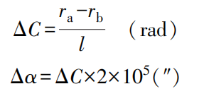
Where
- ΔC – Taper error (rad);
- Δα – Conical angle error (“);
- r₀ – Reading at point b of the cone (mm);
- r₁ – Reading at point a of the cone (mm).
Using 1rad = 57.3° ≈ (2×10⁵)” as the conversion factor from radians to seconds, obtain the error ΔC of the measured conical angle (α).
Example: A sine bar with a center distance L=200mm is used to measure a Morse No. 4 taper plug gauge with a nominal conical angle of 2°58’30.6″ (2.975179°). The measurement is performed as shown in Figure 1-91. If the distance between measuring points a and b is l=80mm, and r₀ – r₁ = 0.01mm, calculate the taper error and the actual conical angle of this taper plug gauge.
Solution: Given L=200mm, l=80mm, then

Since r₀ – r₁ = 0.01mm, point a is higher than point b, the actual conical angle is greater than the nominal conical angle.
αreal =α’+Δα=2°58’30.6″+25″=2°58’55.6″
3. Inspection of eccentricity
(1) When the precision requirement for eccentricity e is not high, use a vernier depth caliper to measure the minimum distance a between the two cylindrical surfaces, then calculate the eccentricity e using the following formula:

(2) When higher precision is required for eccentricity e, use the following inspection method: Precisely measure the eccentricity e using a dial indicator as shown in Figure 22.
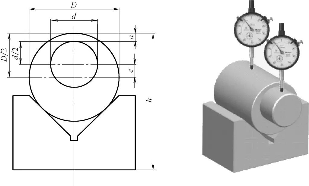
D and d values need to be measured with a micrometer, then calculate the eccentricity e using the formula. For eccentric workpieces on a chuck or eccentric shafts with center holes at both ends, the dial indicator’s probe can be placed in contact with the eccentric part. Rotate the eccentric shaft by hand, and half of the difference between the maximum and minimum values indicated on the dial indicator is the eccentricity e.
(3) Measuring eccentricity using a dial indicator and lathe cross slide.
For workpieces with larger eccentricity, the cross slide scale on a lathe can be used to compensate for the limited measurement range of the dial indicator. During measurement, first bring the dial indicator into contact with the eccentric outer circle of the workpiece, find the highest point, and record the reading and the cross slide scale value.
Then rotate the workpiece 180°, move the cross slide inward, find the lowest point of the eccentric circle, bring the dial indicator into contact with the lowest point of the eccentric circle, and adjust the cross slide to maintain the original dial indicator reading. At this point, the movement distance of the cross slide obtained from the cross slide dial is twice the eccentricity.
4. Inspection of standard threads
(1) Measurement of major diameter.
When the requirements for thread major diameter are not high and the tolerance band is wide, vernier calipers or external micrometers can be used for measurement.
(2) Measurement of thread pitch.
Thread pitch can be measured using a steel ruler. For standard threads with generally small pitches, it is best to measure the length of several pitches and then divide the measured pitch length by the number of pitches to obtain the dimension of a single pitch. For larger pitches, measure the length of 2 or 4 pitches and then calculate the pitch dimension.
The pitch of fine threads is smaller, making it difficult to measure with a steel ruler. Generally, a pitch gauge is used for measurement. When measuring, insert the pitch gauge plate parallel to the axis direction into the tooth shape. If it fits perfectly, it indicates that the pitch of the measured thread is correct.
(3) Measurement of pitch diameter.
1) Measuring the pitch diameter of triangular threads using a thread micrometer.
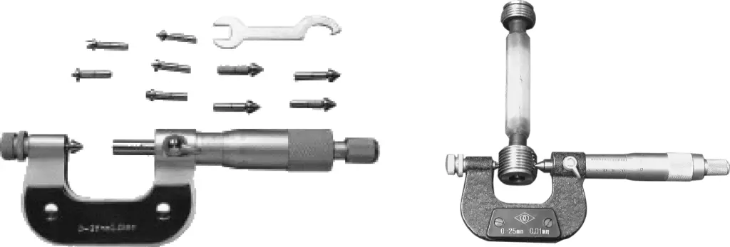
The structure and usage method of a thread micrometer are similar to that of a regular outside micrometer, except that its two measuring contacts are a cone and a groove with the same shape as the thread tooth. During measurement, the two contacts fit precisely on the thread tooth faces, and the reading on the micrometer at this point is the pitch diameter of the thread.
Thread micrometers come with a series of tooth face profiles and measuring contacts for different pitches. When measuring pitch diameters of different specifications of triangular threads, appropriate measuring contacts need to be exchanged, as shown in Figure 23.
2) Wire measurement method.
Selection of wire diameter and precision: The wire diameter that is tangent to the tooth side face at the pitch line of the measured thread is called the “best wire diameter”. Simplified formulas for the best wire diameter are shown in Table 1. Using the best wire for measurement eliminates the influence of thread tooth half-angle error.
Table 1 Simplified formulas for best wire diameter
| Common threads | 55° Whitworth threads | Trapezoidal threads |
| 0.57735P | 0.56370P | 0.51765P |
Commonly used wire measurement methods include the three-wire method and single-wire method for measuring thread pitch diameter. When using the three-wire method to measure external thread pitch diameter, place three wires of the same set into the thread grooves on both sides of the measured thread as shown in Figure 24. Use a precise measuring instrument such as an outside micrometer, lever micrometer, optical comparator, or length measuring machine to directly measure the distance M between the outer sides of the wires, then calculate the actual pitch diameter of the measured thread.
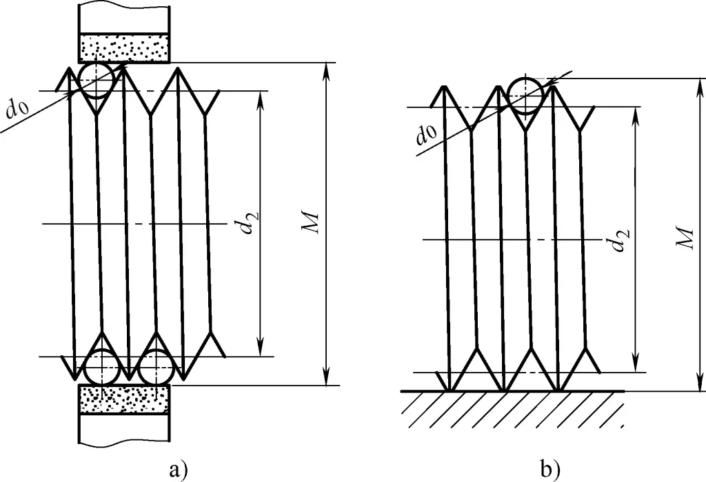
a) Three-wire measurement
b) Single-wire measurement
Commonly used wire diameter size series are shown in Table 2. Pitch diameter calculation formulas for common threads are shown in Table 3.
Table 2 Commonly used wire diameter size series
| 0.118 | 0.201 | 0.291 | 0.433 | 0.724 | 1.157 | 2.020 | 3.177 |
| 0.142 | 0.232 | 0.343 | 0.461 | 0.866 | 1.441 | 2.311 | 3.486 |
| 0.170 | 0.260 | 0.402 | 0.572 | 1.008 | 1.732 | 2.886 | — |
Table 3 Pitch diameter calculation formulas for common threads
| Thread type | Tooth angle α | Pitch diameter calculation formula |
| Common threads | 60° | d2 =M-(3d o -0.866P) |
| 55° Whitworth threads | 55° | d2 =M-(3.1657do -0.9605P) |
| Trapezoidal threads | 30° | d2 =M-(4.8637do -1.866P) |
(4) Comprehensive measurement of threads.
Before comprehensively measuring threads, first check the diameter, tooth profile, and pitch of the thread, then use thread gauges for measurement. When using thread gauges, do not forcefully twist them to avoid damaging the measuring surface and reducing its accuracy.
Thread ring gauges and plug gauges are usually used for comprehensive measurement of various dimensional accuracies of threads. Ring gauges are used to measure external thread dimensional accuracy, while plug gauges are used to measure internal thread dimensional accuracy.
When measuring threads, if the GO end of the gauge can be screwed in but the NOT GO end cannot, it indicates that the thread accuracy meets the requirements. In actual production, for lower precision requirements, standard nuts and screws can also be used for checking, judging by the smoothness and looseness when screwing onto the workpiece.
5. Measurement of worm gears
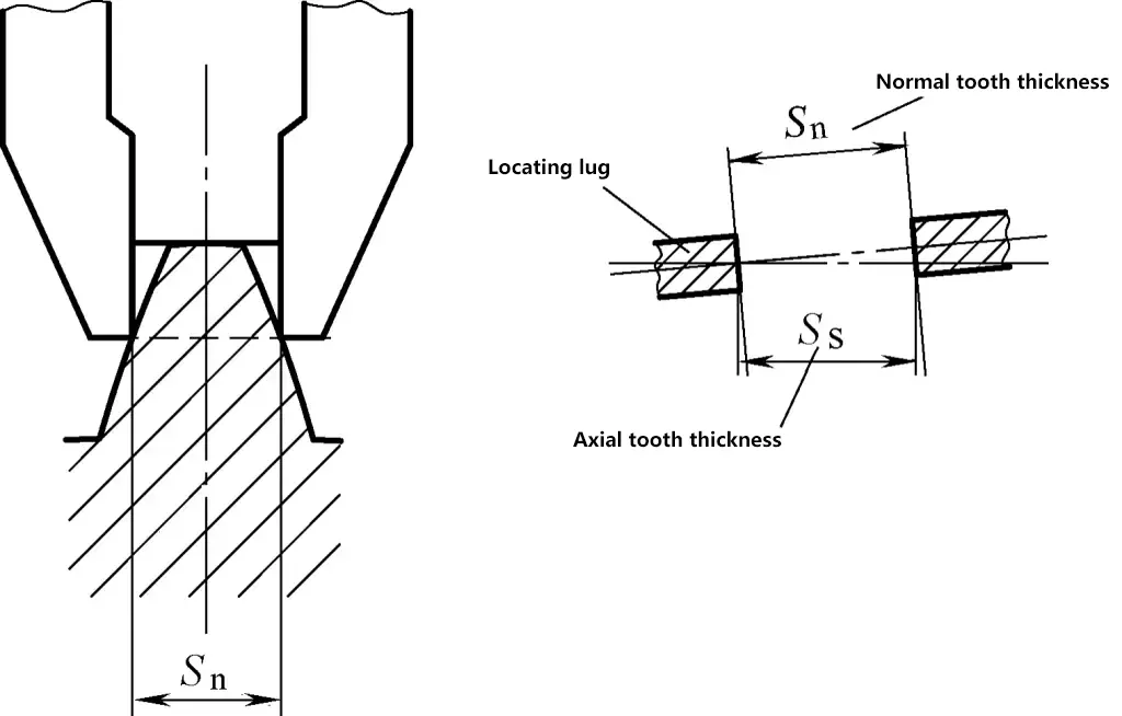
(1) Measuring the normal tooth thickness of worm gears using a vernier tooth caliper, as shown in Figures 25 and 26.

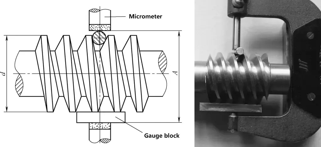
To improve measurement accuracy, the tooth thickness deviation can be converted to the span distance deviation in three-wire measurement, and then measured using the single-wire method, as shown in Figure 27. When α=20°, the single-wire measurement calculation formula is:
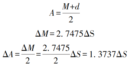
Where
- A – Micrometer measurement size in single-wire measurement (mm);
- M – Micrometer measurement size in three-wire measurement (mm);
- ΔM – Span distance deviation in three-wire measurement (mm);
- d – Actual measured diameter of worm gear outside diameter (mm);
- ΔA – Wire measurement distance deviation in single-wire measurement (mm);
- ΔS – Tooth thickness deviation (mm).
(2) The radial runout of the worm gear addendum circle can be checked using a dial indicator on a runout tester. Slowly rotate the worm gear one full turn by hand, and the maximum variation in the dial indicator reading is the radial runout error.
(3) Checking the tooth profile error of Archimedes worm gears should be done on the axial section, using instruments such as a universal tool microscope.
Skill master’s experience sharing:
Since single-wire measurement uses the addendum circle diameter as the measurement reference, although d in Figure 27 is defined as the actual measured size of the addendum circle, to ensure measurement accuracy, the concentricity between the addendum circle diameter and the worm gear pitch circle must be guaranteed during turning.
III. Inspection of Common Shape and Position Accuracy
1. Detection of straightness error
(1) Detecting straightness errors of cylinders and cuboids
As shown in Figure 28.
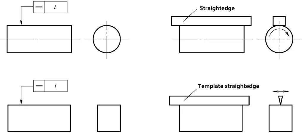
1) Inspection tools: Straightedge (or template straightedge), feeler gauge.
2) Clamping and operation method:
① Place a straightedge or template ruler in direct contact with the measured element line, minimizing the maximum gap between them. The maximum gap at this point is the straightness error of the measured element line. The magnitude of the error should be determined by measuring the light gap. When the light gap is small, it can be estimated using a standard light gap; when it’s larger, a feeler gauge can be used for measurement.
② Measure several element lines using the above method and take the largest error value as the straightness error of the measured part.
(2) Detecting straightness error of conical bodies
As shown in Figure 29.

1) Inspection tools and equipment: surface plate, fixed and adjustable supports, measuring frame, dial indicator or micrometer.
2) Mounting and operation method: Adjust the two endpoints of the measured element line to be at the same height as the surface plate.
① Measure along the full length of the measured element line, recording the readings. Calculate the straightness error using the calculation method (or graphical method) based on the minimum condition (or the two-point line method) using the recorded readings.
② Measure several element lines using the above method and take the largest error value as the straightness error of the measured part.
(3) Detecting straightness error of shaft-type parts on a runout inspection device
As shown in Figure 30.

1—Center support
2—Measured part
3—Indicator
4—Surface plate
1) Inspection tools and equipment: surface plate, center support or runout inspection device, dial indicator, stand, dial indicator or micrometer.
2) Mounting and operation method: Install the measured part between two centers parallel to the surface plate.
① Measure along two element lines in the vertical axis cross-section, recording the readings M₀ and M₁ from the two indicators at their respective measurement points. Take half the difference of the readings at each point {i.e., (M₂-M₃)/2} and use the maximum difference as the straightness error of the axis in that cross-section.
② Measure several element lines in multiple cross-sections using the above method and take the largest error value as the straightness error of the measured part’s axis.
2. Detection of flatness error
(1) Measuring flatness error of high-precision small planes
As shown in Figure 31.

1) Inspection tools and equipment: optical flat.
2) Operation method: Place the working surface of the optical flat on the measured surface with slight pressure, and interference fringes will appear.
The flatness error of the measured surface is the number of closed interference fringes multiplied by half the wavelength of light. For open interference fringes, it is the ratio of the fringe curvature to the distance between adjacent fringes, multiplied by half the wavelength of light. This method is suitable for measuring high-precision small planes.
(2) Detecting flatness error using a spirit level
As shown in Figure 32.
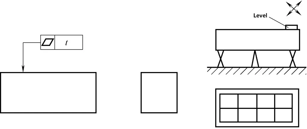
1) Inspection tools and equipment: surface plate, spirit level, bridge plate, fixed and adjustable supports.
2) Mounting and operation method: Adjust the measured surface to a horizontal position, use the spirit level to measure the surface point by point according to a specific layout and direction, record the readings, and convert them to linear values.
Calculate the flatness error using calculation method (or graphical method) according to the minimum conditions (or diagonal method) based on the values of each line.
3. Detection of roundness error
(1) Detection of one of the roundness errors of cone and cylinder
As shown in Figure 33.
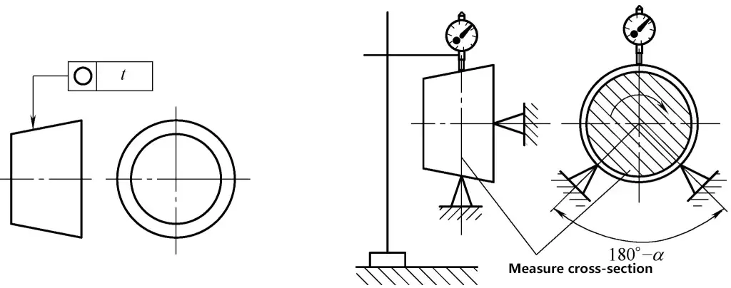
1) Inspection measurement and tools: flat plate, measuring stand with indicator, V-block, fixed and adjustable supports.
2) Clamping and operation method: Place the workpiece on the V-block, with its axis perpendicular to the measurement cross-section, while fixing the axial position.
① During one revolution of the workpiece, half of the maximum difference in indicator readings is the roundness error of that cross-section.
② Measure several cross-sections using the above method, and take the maximum error value as the roundness error of the workpiece.
The reliability of this measurement method depends on the combined effect of the cross-section shape error and the V-block angle. Commonly used angles are α=90° and 120° or 72° and 108° with two V-blocks for separate measurements.
This method is suitable for measuring odd-lobed shape errors on inner and outer surfaces (even-lobed shape errors are measured using the two-point method). During measurement, either the workpiece or the measuring instrument can be rotated.
(2) Detection of roundness error of cone and cylinder II
As shown in Figure 34.
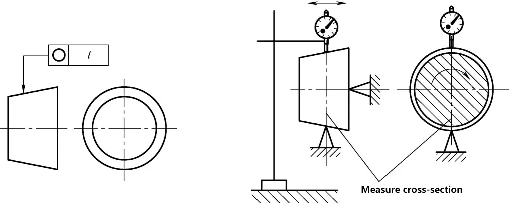
1) Inspection measurement and tools: flat plate, measuring stand with indicator, support, micrometer.
2) Clamping and operation method: Position the workpiece axis perpendicular to the measurement cross-section while fixing the axial position.
① During one revolution of the workpiece, half of the maximum difference in indicator readings is the roundness error of a single cross-section.
② Measure several cross-sections using the above method, and take the maximum error value as the roundness error of the workpiece.
This method is suitable for detecting even-lobed shape errors on inner and outer surfaces (odd-lobed shape errors are measured using the three-point method). During measurement, either the workpiece or the measuring instrument can be rotated.
The two-point method for measuring roundness error is similar to measuring external diameter with a micrometer or internal diameter with an internal dial gauge. Measure at several positions around the circumference and take half of the maximum difference between two diametrically opposed points as the roundness error.
4. Detection of cylindricity error
(1) Detection of cylindricity error of cylinder and shaft I
As shown in Figure 35.

1—Indicator
2—Workpiece
3—V-block
4—Flat plate
1) Inspection measurement and tools: flat plate, V-block, measuring stand with indicator.
2) Clamping and operation method: Use the three-point method to measure cylindricity. Place the workpiece in a V-block on the flat plate, with the V-block longer than the workpiece.
① During one revolution of the workpiece, measure the maximum and minimum readings on one cross-section.
② Using the above method, continuously measure several cross-sections, then take half of the difference between the maximum and minimum readings from all measured cross-sections as the cylindricity error of the workpiece. This method is suitable for measuring odd-lobed shape errors on outer surfaces.
For accurate measurement, usually use two V-blocks with angles α=90° and 120° for separate measurements.
(2) Detection of cylindricity error of cylinder and shaft II
As shown in Figure 36.

1—Indicator
2—Workpiece
3—Right angle seat
4—Flat plate
1) Inspection measurement and tools: flat plate, right angle seat, measuring stand with indicator.
2) Clamping and operation method: Use the two-point method to measure cylindricity. Place the workpiece on the flat plate, close to the right angle seat.
① During one revolution of the workpiece, measure the maximum and minimum readings on one cross-section.
② Using the above method, measure several cross-sections, then take half of the difference between the maximum and minimum readings from all measured cross-sections as the cylindricity error of the workpiece. This method is suitable for measuring even-lobed shape errors on outer surfaces.
5. Detection of line profile error
As shown in Figure 37

1) Inspection measurement and tools: Profile template.
2) Clamping and operation method: Place the profile template on the workpiece in the specified direction, estimate the size of the gap using the light gap method, and take the maximum gap as the line profile error of the workpiece.
6. Detection of parallelism error
(1) Detection of parallelism error between two parallel surfaces
As shown in Figure 38.
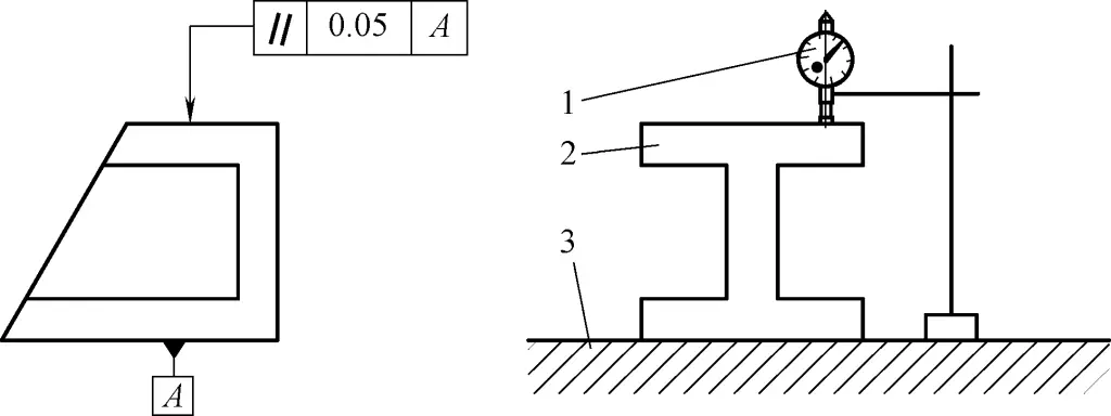
1—Indicator
2—Workpiece
3—Flat plate
1) Inspection measurement and tools: flat plate, stand, dial indicator or micrometer.
2) Clamping and operation method: Place the workpiece on the flat plate and measure along specified measurement lines across the entire surface to be measured.
① Take the difference between the maximum and minimum indicator readings as the parallelism error of the workpiece.
② Take the difference between the maximum and minimum indicator readings within any given length l on each measurement line as the parallelism error of the workpiece.
(2) Detection of parallelism error of internal hole relative to the reference plane
As shown in Figure 39.
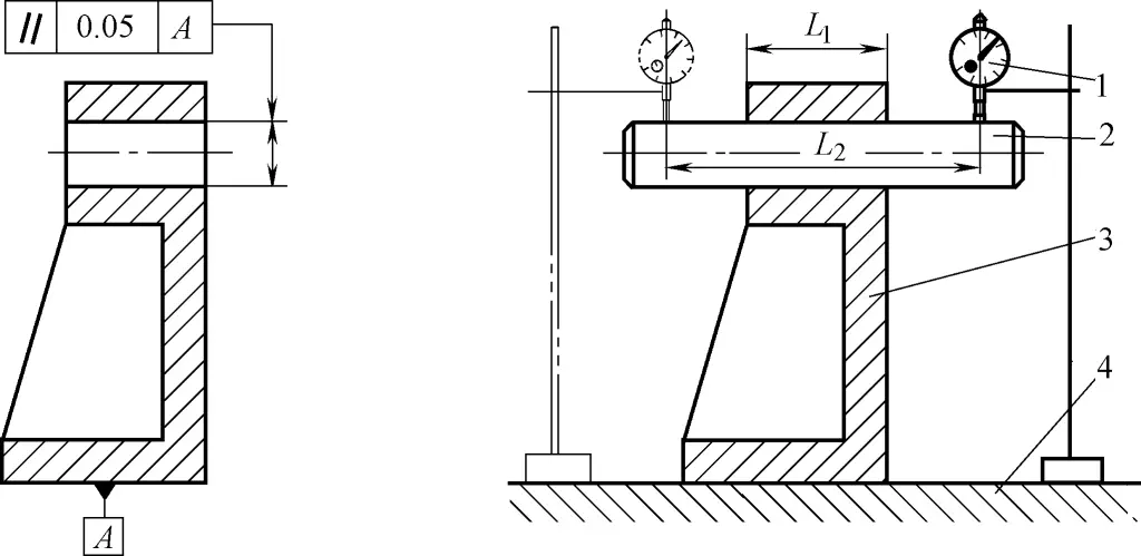
1) Inspection measurement and tools: flat plate, measuring stand with indicator, mandrel.
2) Clamping and operation method: Place the workpiece directly on the flat plate, with the axis to be measured simulated by the mandrel. Readings M₀ and M₁ are obtained at two positions with a measurement distance of L₂. Then
Parallelism error f=L₀/L₁|M₁-M₂|, where L₂ is the length of the workpiece axis.
Use an expandable mandrel (forming a clearance-free fit with the hole) for measurement.
7. Detection of perpendicularity error
(1) Detection of perpendicularity error of right-angle seat type workpiece
As shown in Figure 40.

1—Right angle seat
2—Workpiece
3—Flat plate
4—Indicator
1) Inspection measurement and tools: flat plate, right angle seat, measuring stand with indicator.
2) Clamping and operation method: Fix the reference surface of the workpiece on the right angle seat, while adjusting the reading difference of the surface to be measured near the reference to be minimal. Take the difference between the maximum and minimum indicator readings obtained at various points on the entire surface to be measured as the perpendicularity error of the workpiece.
(2) Detection of perpendicularity error of stepped shaft outer circle relative to end face
As shown in Figure 41.
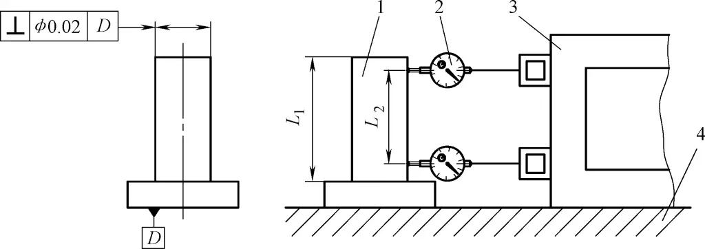
1—Workpiece
2—Indicator
3—Square box
4—Flat plate
1) Inspection measurement and tools: square box, flat plate, magnetic stand with indicator.
2) Clamping and operation method: Place the workpiece on the flat plate and measure in two perpendicular directions (x, y).
Measure the distances M₁ and M₂ between the profile element to be measured and the square box at two positions with a distance of L₀, and the corresponding shaft diameters d₃ and d₄. The perpendicularity error in the measurement direction is:

Take the larger of the errors measured in the two measurement directions as the perpendicularity error of the workpiece.
8. Detection of coaxiality error
(1) Detection of coaxiality error of stepped shaft with center hole reference
As shown in Figure 42.
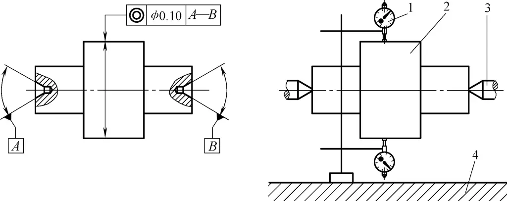
1—Indicator
2—Workpiece
3—Center support
4—Flat plate
1) Inspection measurement and tools: flat plate, center support, measuring stand with indicator.
2) Clamping and operation method: Mount the workpiece between two centers, and zero both indicators in the vertical axis cross-section.
① Measure axially, take the difference in readings |M₀-M₁| of the indicators at corresponding points on the cross-section perpendicular to the reference axis as the coaxiality error on that cross-section.
② Rotate the workpiece and measure several cross-sections using the above method. Take the maximum value (absolute value) of the reading differences obtained from each cross-section as the coaxiality error of the workpiece.
(2) Detection of coaxiality error of stepped shaft without center hole
As shown in Figure 43.

1—Indicator
2—Workpiece
3—V-block
4—Flat plate
1) Inspection measurement and tools: flat plate, V-block, measuring stand with indicator.
2) Mounting and operation method: Place one end of the reference surface of the part to be measured on the V-shaped frame, then make the indicator contact the surface to be measured. Rotate the part to be measured on the V-shaped frame for one revolution, and the variation of the indicator is the coaxiality error of the part.
(3) Detection of coaxiality error of outer circle relative to inner hole of sleeve
As shown in Figure 44.
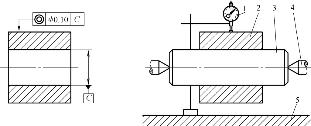
1—Indicator
2—Part to be measured
3—Mandrel
4—Center support
5—Flat plate
1) Inspection quantity and instruments: Center support, mandrel, measuring stand with indicator.
2) Mounting and operation method: Insert the standard mandrel into the hole of the part to be measured and mount it between two centers.
Make the indicator contact the surface to be measured, rotate the part to be measured, and the variation of the indicator is the coaxiality error of the part.
9. Detection of symmetry error
(1) Detection of symmetry error of concave groove relative to outer contour
As shown in Figure 45.

1—Part to be measured
2—Indicator
3—Flat plate
1) Inspection quantity and instruments: Measuring stand with lever dial indicator, flat plate.
2) Mounting and operation method: Place the part to be measured on the flat plate, use the lever dial indicator to measure the reading of the first side of the concave groove relative to the outer contour (reference A), zero the indicator, flip the edge to measure the second side, and the absolute value of the maximum reading difference is the symmetry error of the part to be measured.
This measurement method does not consider the shape error of reference A.
(2) Detection of symmetry error of keyway on shaft relative to shaft outer circle
As shown in Figure 46.
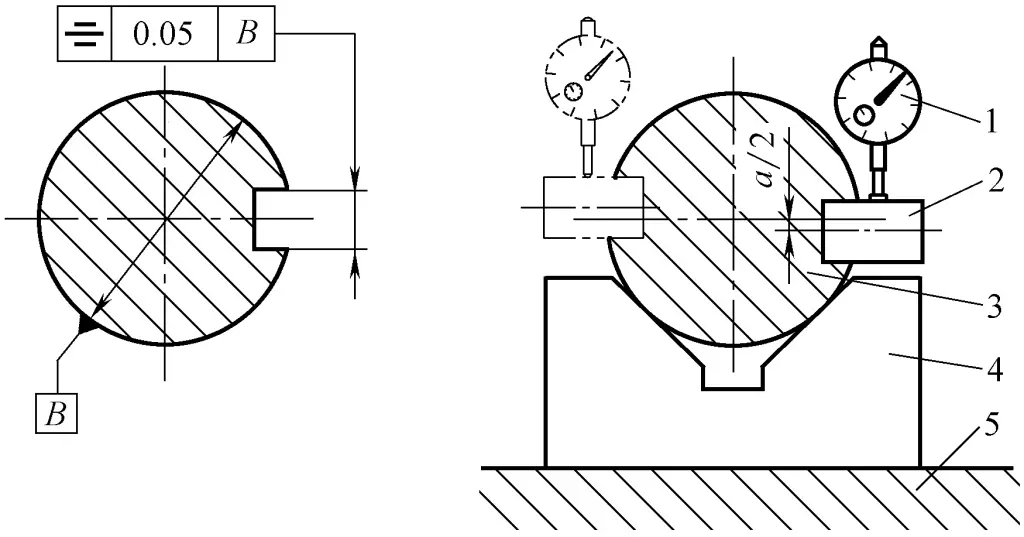
1—Indicator
2—Positioning block
3—Part to be measured
4—V-shaped frame
5—Flat plate
1) Inspection quantity and instruments: Flat plate, V-shaped frame, positioning block, measuring stand with indicator.
2) Mounting and operation method: The reference axis is simulated by the V-shaped frame, and the center plane to be measured is simulated by the positioning block. The measurement is done in two steps:
① Cross-section measurement. Adjust the part to be measured so that the positioning block is parallel to the flat plate in the radial direction, measure the distance from the positioning block to the flat plate, then flip the part to be measured 180° and repeat the above measurement to obtain the reading difference a of the two corresponding points on the upper and lower sides of the cross-section. The symmetry error of this cross-section is:
fcross=ah/(d-h)
Where
- d – diameter of the shaft;
- h – depth of the groove.
② Longitudinal measurement. Measure along the length of the keyway, and take the maximum reading difference of two points in the longitudinal direction as the symmetry error in the longitudinal direction:
flong=ahigh-alow
Take the maximum value of the errors measured in the above two directions as the symmetry error of the part.
10. Detection of circular runout error
(1) Detection of circular runout error of stepped shaft
As shown in Figure 47.
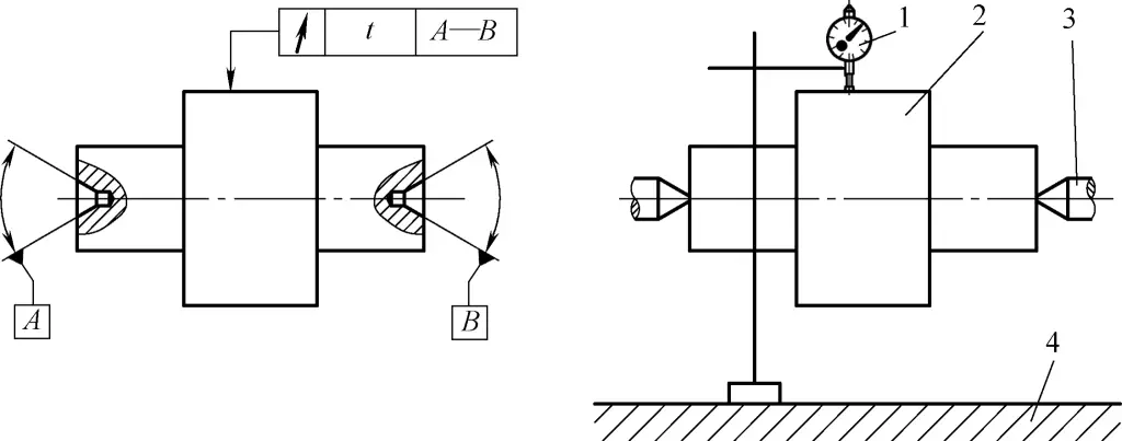
1—Indicator
2—Part to be measured
3—Center support
4—Flat plate
1) Inspection quantity, instruments and mounting: A pair of coaxial centers, measuring stand with indicator.
2) Mounting and operation method: Install the part to be measured between two centers.
① During one revolution of the part to be measured, the maximum difference in the indicator readings is the radial circular runout error on a single measuring surface.
② Measure several cross-sections according to the above method, and take the maximum value of the runout measured on each cross-section as the radial circular runout error of the part.
(2) Detection of circular runout error of sleeve outer circle relative to inner hole
As shown in Figure 48.
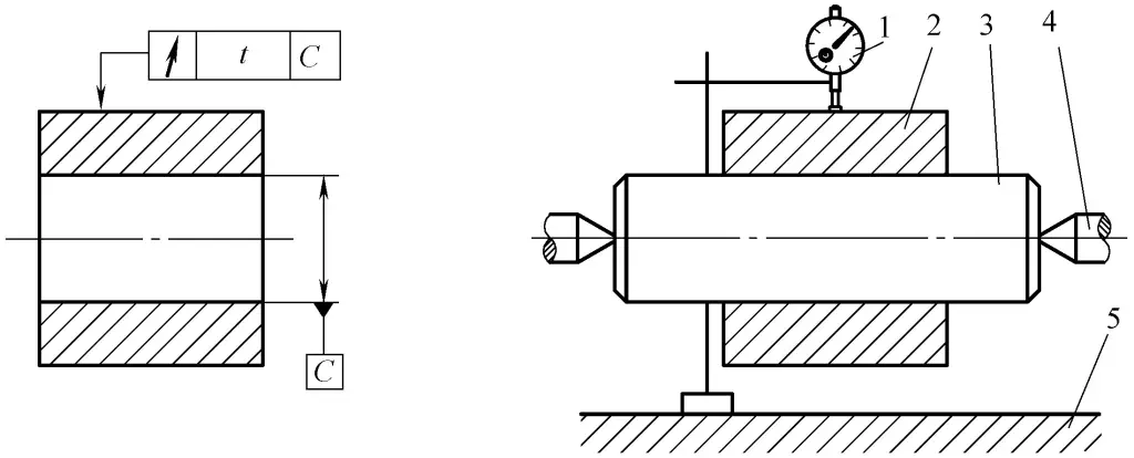
1—Indicator
2—Part to be measured
3—Mandrel
4—Center support
5—Flat plate
1) Inspection quantity, instruments and mounting: A pair of coaxial centers, guided expandable mandrel, measuring stand with indicator.
2) Mounting and operation method: Fix the part to be measured on the guided expandable mandrel and install it between two centers.
① During one revolution of the part to be measured, the maximum difference in the indicator readings is the radial circular runout error on a single measuring surface.
② Measure several cross-sections according to the above method, and take the maximum value of the runout measured on each cross-section as the radial circular runout error of the part.

