Step-by-Step Guide to Repairing Hydraulic Cylinders on a Press Brake
Hydraulic cylinders are the powerhouse behind the efficient operation of press brakes, but when they falter, it can bring your…
When sheet metal components are subjected to unexpected impacts and collisions, they undergo changes in shape, rendering them unusable and affecting production. In order to save costs, reduce raw material consumption, and quickly resume production, it is necessary to restore the deformed sheet metal components to their original state for reuse. This process of restoring the original shape is called repair.
Due to prolonged wear and tear as well as impacts from external forces, some sheet metal components often become deformed, rendering them unusable.
However, through manual repair and correction, we can restore the damaged and deformed sheet metal components to their original state, thereby extending the service life of the components and reducing production costs. Below, we will introduce some methods for repairing damaged and deformed sheet metal components.

To repair damaged and deformed sheet metal components, it is essential to first understand the main causes and various factors leading to their deformation. Subsequently, different repair methods can be developed for different situations.
The primary cause of sheet metal component deformation is when the component undergoes external impacts and collisions, leading to local metal fibers being stretched or compressed, resulting in changes to the overall fiber layout and causing metal fibers to become misaligned, thus leading to an imbalance in the overall metal fiber layout.
The repair of sheet metal components primarily addresses the above-mentioned reasons by using external forces and heat to induce changes in the misaligned local metal, causing the elongated metal fibers to contract or the contracted metal fibers to elongate. This process aims to maintain the overall length of the metal fibers, thereby achieving the goal of repair and restoring the sheet metal components to their original state.
During the repair process of damaged and deformed sheet metal components, different repair methods are formulated for different situations. The main methods of repair include manual correction, flame correction, and mechanical correction.
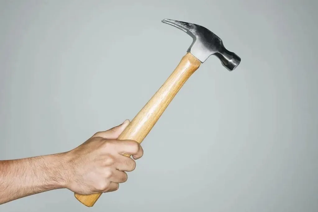
Manual correction is primarily carried out using simple tools such as large hammers, hammers, wooden mallets, rubber mallets, wrenches, and vise grips to achieve the purpose of repair through hammering, tapping, twisting, and other manual operations, utilizing the changes in the metal fibers of the sheet metal components and the transformation of their shapes.
Flame correction involves using the method of thermal expansion and contraction, where the flame is directed at the locally deformed part of the workpiece to induce plastic deformation due to heating, and after cooling, the elongated local metal fibers will contract, thereby maintaining the overall length of the metal fibers and achieving the goal of correcting the deformation and restoring the original state.
Mechanical correction is mainly used for large sheet metal components that cannot be corrected manually or by flame correction. This method utilizes mechanical equipment and large tools for rolling and leveling the components to achieve the purpose of repair.
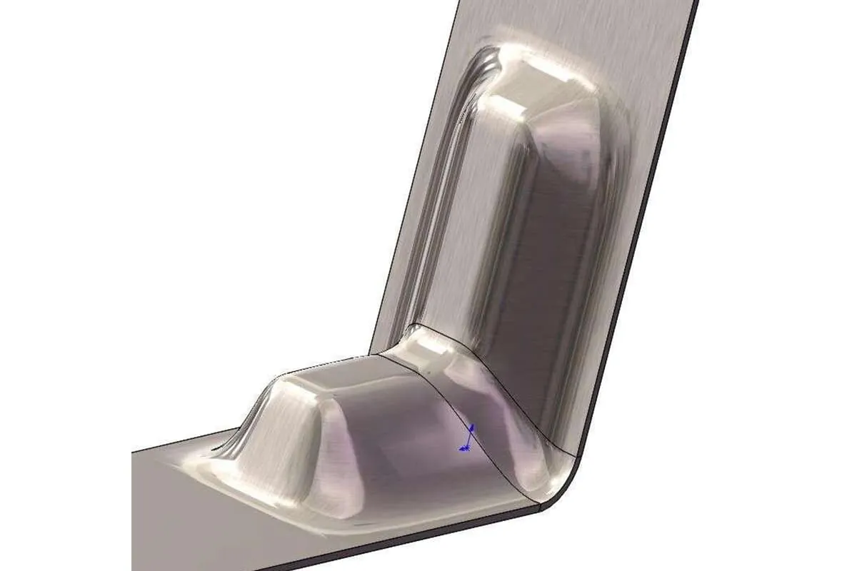
When sheet metal components are impacted or collided with external forces, the components will deform, forming an irregular shape with a high center and concave edges. Depending on the type of deformation, our repair methods vary accordingly.
The convex deformation (commonly known as bulging) in the middle and concave edges of sheet metal components is caused by the longitudinal and transverse metal fibers in the plate being stretched in the middle, while the metal fibers around the edges remain unchanged, resulting in tightness around the metal fibers and looseness in the middle, forming a bulge.
The correction and repair method is to use the basic principle of folding and unfolding. Without flanging or bending, place the disassembled or cut-off deformed component on a platform, and use a hammer to strike the edge of the bulge, and then radiate the hammering from the bulge to the periphery, with the hammering density and force increasing as it goes outward.
This will cause different parts of the metal to stretch and relax to varying degrees from the inside out, and the bulging deformation will gradually disappear during the hammering process.
If there are several adjacent bulges in the middle of the steel plate, gently hammer the junction to merge the bulges into one, and then hammer the periphery to flatten it.
The irregular twists and waves around the edges of sheet metal components are caused by local metal fibers around the edges being impacted or collided with external forces, causing the metal fibers to be stretched and elongated in the longitudinal and transverse directions, but the middle metal fibers remain unchanged, resulting in a phenomenon of tightness in the middle and looseness around the edges.
The repair method is to place the disassembled or cut-off deformed component on a platform, and use a hammer or large hammer to hammer from the inside out (i.e. from the middle to the periphery), and then from the outside in.
The hammering method is a circular hammering method, with even hammer points and increasing hammering force as it goes inward. This will cause the middle metal fibers of the component to stretch and relax, keeping the length consistent with the metal fibers around the edges, thereby eliminating the irregular twists and waves and restoring the component to its original shape.
In summary, the hammering correction method can be summarized in one sentence, that is: hammer the tight part in the middle and the edges for the bulging part. In other words, hammer where it is tight (i.e. where it needs to be corrected).
When the sheet metal component is bent and twisted, the other end of the disassembled or cut-off sheet metal component can be clamped on the platform vise, and the deformed end of the sheet metal component can be clamped with a self-made fork-shaped wrench or a large adjustable wrench, and twisted in the opposite direction of the twist.
After the bending and twisting deformation disappears, gently strike the deformed part with a hammer until it is flattened and fixed.
If it is a large sheet metal component that is difficult to disassemble and not allowed to be cut off, the self-made fork-shaped wrench or large adjustable wrench can be directly used to twist it in the opposite direction of the twist, until the twisting deformation disappears. Then, use a support iron plate to cushion the back and gently hammer the deformed part until it is corrected and restored to its original position.
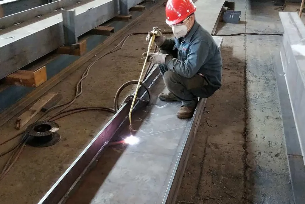
When a sheet metal component is locally impacted or deformed and cannot be easily removed from the machine for correction using manual hammering, or when the structure of the sheet metal component itself makes it difficult to use manual correction (such as when there are flanges and bends around the periphery), the flame heating correction method can be used to eliminate the protrusions or wavy deformations.
The steps are as follows:
1) Use a welding torch (i.e., a welding gun) to heat the highest point of the bulge to cherry red. The heating range should be determined according to the degree of deformation: when the protrusion is severe and the area is large, the heating point should be larger (approximately 20-30mm in diameter); when the degree of shrinkage is lighter and the area is smaller, the heating point should be smaller (approximately 10-15mm in diameter).
2) After heating, rapidly strike the area around the heating point with a wooden hammer, then strike the heating point, and when striking, use a backing plate to support the workpiece as appropriate. After the wooden hammer strikes stop, rapidly cool the heating point with water, and then gently flatten it with a hammer or a sheet metal hammer.
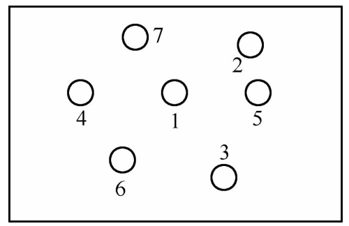
3) If slight shrinkage does not solve the problem, heat and strike the deformed area point by point in the sequence shown in Figure 3-29 until it is corrected.
When performing flame heating correction, caution should be exercised. If it can be avoided, try not to use flame heating as much as possible to prevent side effects. When heating, the welding nozzle should be vertical and slightly pressed down, so that the heating is fast and the heat is not easily dispersed, resulting in significant effectiveness.
However, be careful not to melt or burn through the sheet metal. The amount of shrinkage should be appropriate, and excessive shrinkage should be avoided. When flattening by striking, do so moderately, avoiding excessive force to prevent the sheet metal from becoming brittle and fracturing.
The sheet metal components with framed cylindrical or box-shaped structures may experience local depression on the surface when subjected to external impact or collision. In such cases, the framework internal support method can be used to repair the depressed area, causing it to rise, followed by hammering to flatten it.
The specific process involves placing a hydraulic jack (or screw jack) underneath the depressed area inside the framework (cylindrical barrel or square box), with the jack head aligned with the lowest point of the depression. The jack base is secured on the framework base.
If the framework is too high and the jack cannot reach the depressed area, wooden blocks or iron plates can be placed on the framework base to stabilize and secure the hydraulic jack base on the blocks, then the jack is tightened. Afterward, a lever is used to operate the hydraulic jack, gradually lifting the jack head upwards until the depression is raised.
If the sheet metal is too thick and difficult to lift, oxyacetylene welding can be used to heat the area around the depression. While heating, the hydraulic jack is gradually raised until the depression rises slightly above the surrounding area. Then, the jack is removed, and a backing plate is placed underneath the depression, while a hammer is used from above until the surface is flattened.
For lateral correction, a screw jack can be used with a similar method, but the correction is performed vertically, turning it into a lateral extrusion correction.
The bolt welding and extraction method is primarily used for cylindrical or box-shaped components. When these components experience local collapse due to external impact and collision, and cannot be corrected by hammering, the bolt welding and extraction method can be employed.
The specific operational process is as follows:
1) Prepare a high-strength long bolt, two spacer blocks, and a perforated pressure plate.
2) Weld the head of the high-strength bolt at the lowest point of the collapsed area. Place the two spacer blocks on either side of the bolt above the collapsed area. Thread the perforated pressure plate onto the high-strength bolt, then tighten the high-strength nut to bring the pressure plate close to the spacer blocks.
Continuously tighten the nut to lift the collapsed area towards the bolt. Tighten the nut until the collapsed area is pulled out and slightly raised above the surrounding surface. Remove the pressure plate and spacer blocks, cut off the high-strength bolt welded in the collapsed area, and then use a hammer to correct the collapsed area.
When using the hammer, a supporting iron backing plate can be placed underneath. If the plate is too thick and cannot be pulled out solely by tightening the nut, oxyacetylene welding can be used to heat the surrounding area of the collapse, then tighten the nut until the collapsed area is pulled out.
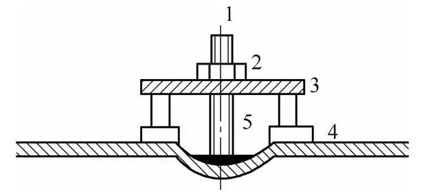
1 – Bolt Rod 2 – Nut 3 – Pressure Plate 4 – Spacer 5 – Heating Area