I. Basic process knowledge
The operation of connecting two or more workpieces with rivets is called riveting. Because riveting is simple to operate and flexible in application, it is generally used in situations where the force is not significant. According to whether the parts can rotate relative to each other after riveting, riveting can be divided into fixed riveting and movable riveting, as shown in Figure 1.
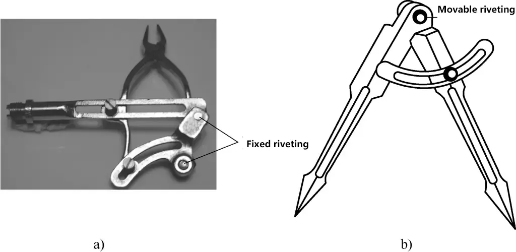
a) Fixed riveting
b) Movable riveting
According to the different riveting methods, riveting operations can be divided into hot riveting, cold riveting, and mixed riveting. Generally, cold riveting is used for rivets with a diameter of less than 8mm.
The following introduces the manual cold riveting operation technique for fitters.
1. Riveting tools
(1) Hammer
The hammer used for fitter riveting is mostly a ball-peen hammer, and its specifications are selected according to the diameter of the rivet. The most commonly used are 0.66kg or 0.88kg ball-peen hammers.
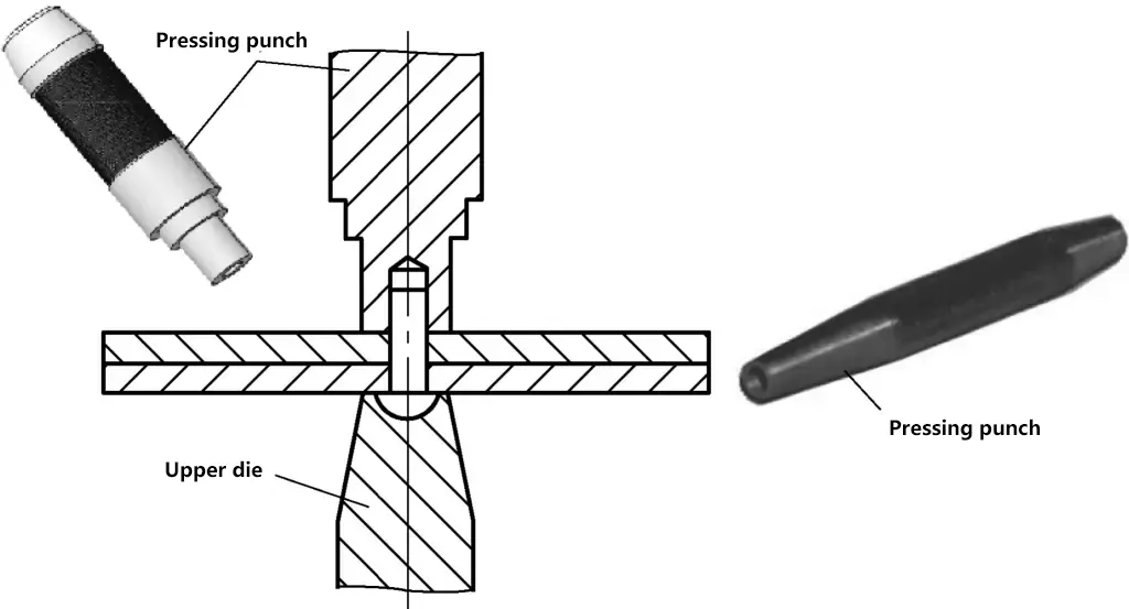
(2) Compressive punch
As shown in Figure 2. After the rivet is inserted into the hole, it is used to press the plates to be riveted tightly and make them fit closely.
(3) Die and cap
When riveting semi-circular head rivets and semi-circular countersunk head rivets, the final riveting forming process is to use the die and cap to shape the rivet head into a regular shape, as shown in Figure 3. The semi-circular concave spherical surface of the die and cap heads should be made according to the standard size of the semi-circular head rivet.

In addition to the main tools mentioned above, supporting tools such as anvils and clamping tools like bench vices are also needed during riveting.
2. Selection of rivets and riveting parameters
(1) Rivet classification
1) According to the different shapes of the rivets, rivets are mainly divided into flat head rivets, semi-circular head rivets, countersunk head rivets, semi-circular countersunk head rivets, and hollow rivets, as shown in Figure 4.
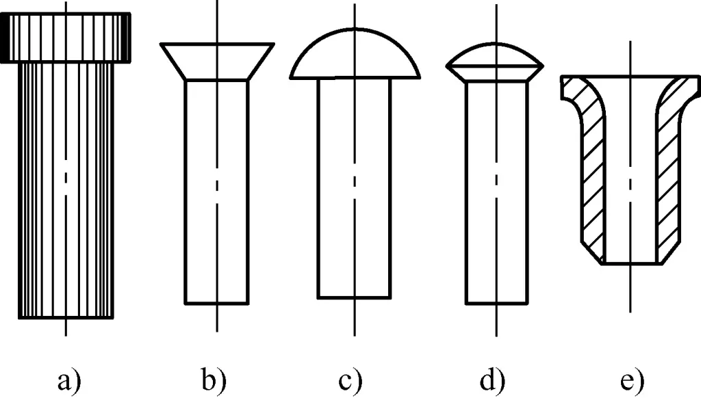
a) Flat head rivet
b) Countersunk head rivet
c) Semi-circular head rivet
d) Semi-circular countersunk head rivet
e) Hollow rivet
2) According to the different uses of the rivets, rivets can be divided into boiler rivets, steel structure rivets, and transmission belt rivets.
3) According to the material of the rivets, rivets can be divided into steel, copper (pure copper and brass), and aluminum.
(2) Riveting parameters
Riveting parameters are shown in Figure 5.
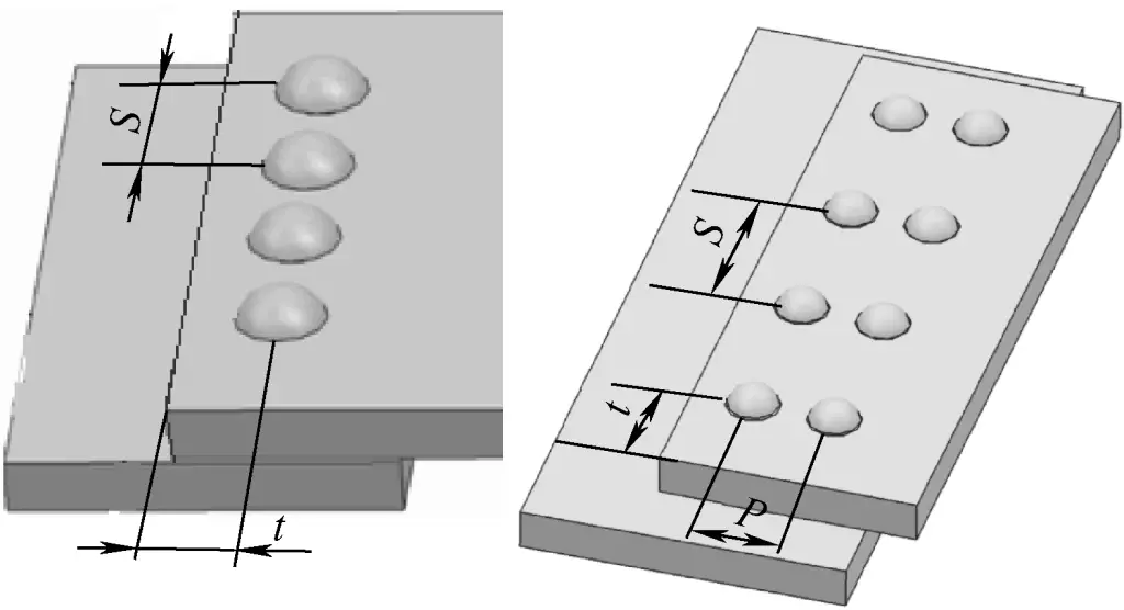
1) Calculation of rivet spacing, edge distance, and row distance
① Single-row riveting
The riveting spacing is S=3d
The riveting edge distance is t=1.5d
Where d is the diameter of the rivet.
② Double-row riveting
The riveting spacing is S=4d
The riveting edge distance is t=1.5d
The riveting row distance is P=2d
2) Determination of rivet diameter
The selection of rivet diameter is generally related to the calculated thickness of the plates to be connected. To ensure that the rivets have enough shear strength, according to experience, the rivet diameter is generally selected according to Table 1.
Table 1 Determination of Rivet Diameter (unit: mm)
| Calculate Thickness | 5~6 | 7~9 | 10~12 | 15~18 | 19~24 | ≥25 |
| Rivet Diameter | 10~12 | 14~18 | 20~22 | 24~27 | 27~30 | 30~36 |
The principle for determining the calculation of thickness is:
- When overlapping plates, calculate based on the thicker one.
- When riveting plates with a significant difference in thickness, the thinner plate’s thickness should be used as the calculation thickness.
- When riveting a plate to a profile, take the average value of the two.
3) Determining the through hole diameter d0 before riveting (see Table 2)
Table 2 Determination of through hole diameter before riveting (unit: mm)
| Rivet diameter d | 2.0 | 2.5 | 3.0 | 4.0 | 5.0 | 6.0 | 8.0 | 10.0 | |
| Through hole diameter d0 | Rough assembly | 2.2 | 2.7 | 3.4 | 4.5 | 5.6 | 6.6 | 8.6 | 11 |
| Precision assembly | 2.1 | 2.6 | 3.1 | 4.1 | 5.2 | 6.2 | 8.2 | 10.3 | |
4) Determination of rivet length
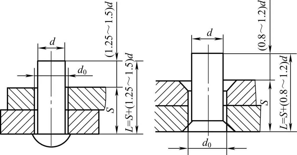
The length of the rivet used in riveting must be sufficient to form a rivet head that meets the requirements and provides enough riveting strength. The length of the rivet includes the total thickness of the plates and the length of the protruding part of the rivet. Generally, the length of the protruding part of a semi-circular head rivet should be 1.25 to 1.5 times the diameter of the rivet, while for countersunk head rivets, it should be 0.8 to 1.2 times the diameter of the rivet, as shown in Figure 6.
II. Basic operational skills
1. Hand riveting process steps
(1) Riveting of semi-circular head rivets
1) Refer to Table 1, select the correct rivet diameter based on the thickness of the parts being riveted; refer to Table 2 to select the correct drill diameter for the rivet hole (through hole diameter) based on the rivet diameter and assembly precision.
If the through hole diameter is too small, the rivet will damage the hole walls of the connecting parts upon insertion, possibly causing cracks; if the hole diameter is too large, the rivet may wobble or bend during riveting, affecting the appearance of the rivet head and significantly reducing riveting strength.
2) Drill or ream holes in the plates to be connected, and remove burrs from the hole edges.
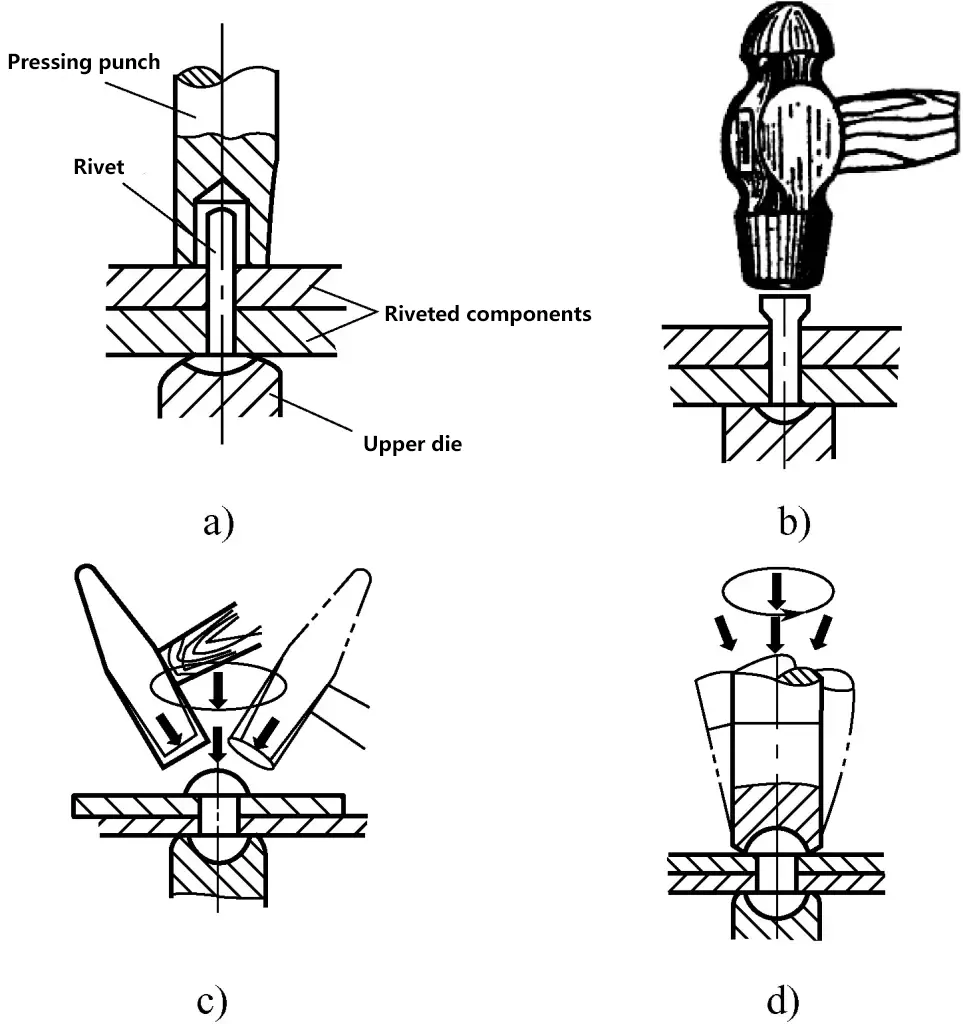
3) Insert the rivet, place the round head of the rivet on the top die, and use the compression punch to tightly clamp the riveting parts together, as shown in Figure 7a.
a) Pressing the riveting parts
b) Upsetting the rivet
c) Hammer forging
d) Using a cover die to finish and form the rivet head
4) As shown in Figure 7b, use a hammer to upset the rivet head.
5) As shown in Figure 7c, hammer and smooth the rivet head to its initial shape.
6) As shown in Figure 7d, use a cover die to finish the rivet head to the required shape. When using the cover die, avoid damaging the rivet head or marring the surface of the workpiece.
(2) Riveting of countersunk head rivets
- Correctly select the drill diameter for the rivet hole using the same method as for semi-circular head rivets.
- After drilling or reaming holes in the plates to be connected, countersink both hole edges.
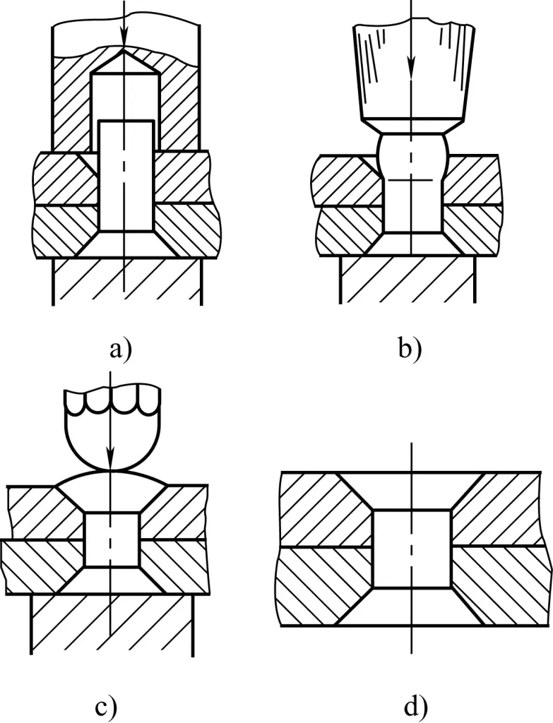
- Insert the countersunk rivet into the rivet hole. If a preformed rivet is available, it only needs to be upset to form the other end head, with the process steps shown in Figure 8.
- If a preformed rivet is not used and instead a properly cut round steel is used as a rivet, proceed as follows:
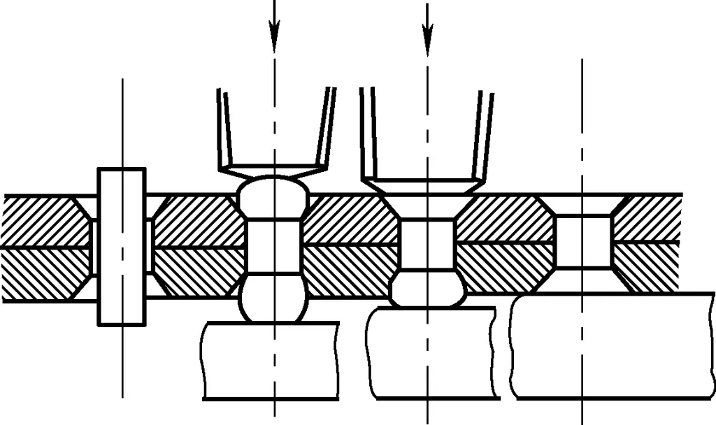
- Insert the cut round steel into the rivet hole, and upset the middle of both ends.
- First rivet one end flat, then the other end, and finally smooth the surfaces of both ends, as shown in Figure 9.
a) Pressing the riveting parts
b) Upsetting the protruding end of the rivet
c) Upsetting and filling the countersink
d) Filing the protruding part of the rivet flush
(3) Precautions for manual riveting with a hammer
- During upsetting, the direction of the hammering force should pass through the rivet axis and should not be skewed to prevent bending of the rivet shaft and misalignment of the rivet head.
- During riveting hammering, avoid any extension of the riveting parts or making dents on the surface.
- While manually hammering riveting, frequently observe the shape changes of the rivet head and adjust the hammering force accordingly. For semi-circular head rivets, after upsetting and forming, observe the rivet head’s shape and adjust the hammering force and contact points as needed to achieve the desired shape.
- When manually riveting, minimize the number of collisions between the hammerhead and the hole edge metal to reduce deformation of the hole edge metal and prevent the occurrence of cracks.
- When manually riveting semi-circular head rivets with a cover die for shaping, be careful to avoid hitting the die and causing it to rebound and injure someone.
(4) Riveting of hollow rivets
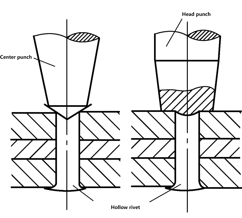
As shown in Figure 10, after inserting the hollow rivet into the hole, first press the workpiece tightly, then use a template punch to expand the edge of the hollow rivet, and finally use a special forming punch to form the rivet head.
(5) About Movable Riveting
In order to make the riveted parts rotate relative to each other after riveting, during movable riveting, in addition to following the above riveting process, the hammering force should be light while flattening the rivet head. Check the movement status while hammering to prevent the parts from being “riveted to death.”
If the riveted parts are difficult to rotate after riveting, you can place a hollow die (similar in shape to the pressing punch) under the rivet head and then hammer the rivet head. This will loosen the rivet, allowing the two riveted parts to move relative to each other. If the parts are too loose, they can be tightened according to the fixed riveting process, allowing the tightness of movable riveting to be adjusted as needed.
2. Disassembly of Riveted Parts
In some equipment maintenance scenarios, riveted parts need to be disassembled to replace components. In this case, the rivet head must be destroyed before using a special punch to push out the rivet, achieving the purpose of disassembling the riveted parts.
(1) Disassembly of Countersunk Rivets
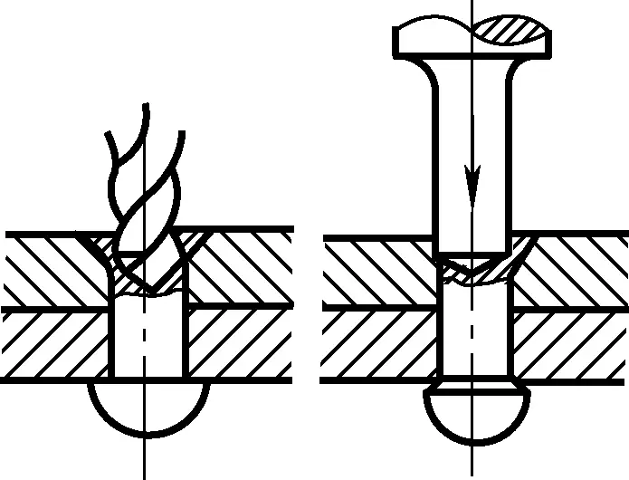
As shown in Figure 11, during disassembly, first use a center punch to make a center hole in the rivet head, then drill a hole with a bit approximately 1mm smaller than the rivet diameter. The hole depth should slightly exceed the height of the rivet head. Finally, insert a punch into the hole and push the rivet out.
(2) Disassembly of Round Head Rivets
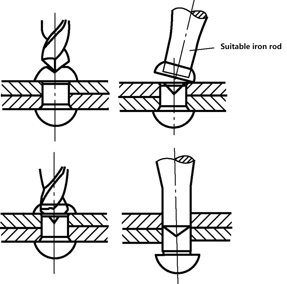
As shown in Figure 12, when disassembling round head rivets, first slightly flatten the rivet head, then use a center punch to create a hole, insert an appropriate rod into the hole to break off the rivet head, and finally use a punch to push out the rivet.
For surfaces with low requirements and rougher areas, you can use a chisel to chisel away the rivet head from around the rivet. This method is generally only suitable for rivets with a diameter of less than ϕ10mm. For parts that cannot have their surface damaged during disassembly, use an appropriate drill bit to drill out the rivet.
3. Causes and Prevention Measures of Riveting Defects
Table 3 Causes and Prevention Measures of Riveting Defects
| Types of Riveting Defects | Defect Illustration | Causes of Defects | Prevention Measures |
| Slanted Rivet Head | 1) Rivet shank too long; 2) Misalignment between two parts and rivet; 3) Hammering force not applied through rivet axis during flattening | 1) Correctly calculate and choose rivet length; 2) Ensure coaxiality when drilling rivet hole; 3) Hammering point should pass through rivet axis | |
| Rivet Head Perimeter Too Large | 1) Rivet shank too long; 2) Rivet die diameter too small | 1) Correctly calculate and choose rivet length; 2) Choose rivet die according to rivet specifications | |
| Uneven Rivet Head | 1) Uneven hammering force, offset or swinging hammer during hammering; 2) Rivet die or top die placed at an angle | 1) Hammering force point through rivet center; 2) Ensure rivet die or top die socket center is concentric with rivet axis | |
| Gap Between Riveted Parts | 1) Uneven surface between workpieces; 2) Pressing punch not pressing sheet tightly | 1) Check whether the surface of workpieces is flat before riveting, and repair the surface if not flat; 2) Correctly calculate and process hole diameter; 3) Ensure pressing punch tightly presses the workpieces before riveting | |
| Surface of Riveted Parts Crushed | 1) Rivet shank too short; 2) Rivet die diameter too large | 1) Correctly calculate and choose rivet length; 2) Choose a rivet die with appropriate diameter | |
| Bent Rivet Shank | Rivet shank diameter too small or riveting hole diameter too large | Correctly calculate and select the through-hole diameter before riveting | |
| Countersunk rivet hole not filled | 1) Rivet length is insufficient; 2) When upsetting the rivet, the hammering direction is not perpendicular to the plane being riveted | 1) Correctly calculate and select the rivet length; 2) When upsetting the rivet, the hammering direction coincides with the center of the rivet shank |

