I. Overview
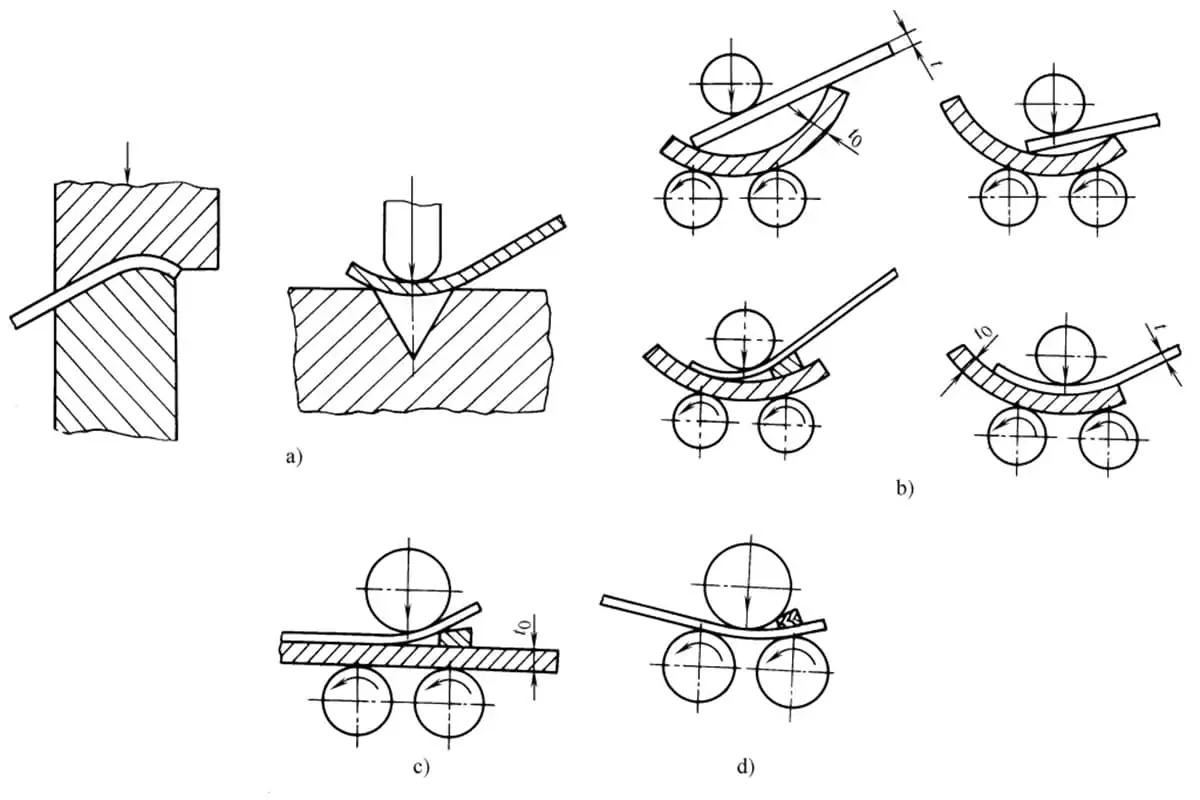
Bending (plate rolling) is a processing method that places the sheet material between 2 to 4 roller shafts, and as the roller shafts rotate, the sheet material is bent along the roller shafts into shape, as shown in Figure 1.
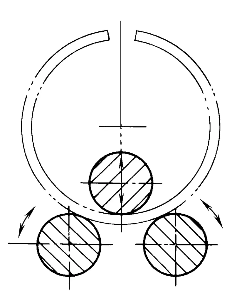
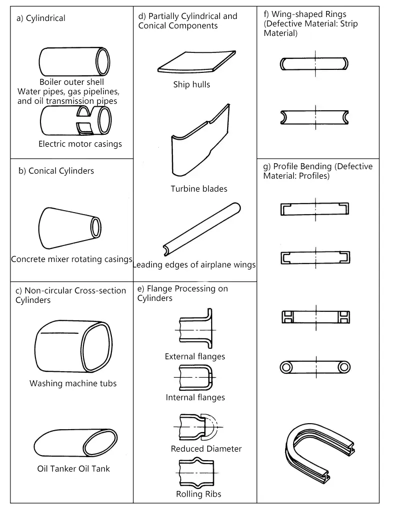
Bending is generally used for parts with large bending radii and is widely used in the processing of cylindrical and conical parts. In addition, since the position of the roller shafts can be appropriately changed relative to the feed amount of the sheet material, it is also possible to produce quadrilateral, elliptical, and other non-circular cross-sectional cylindrical parts, and it can also be used for flanging processing of cylindrical and non-circular cross-sectional cylindrical parts, as shown in Figure 2.
II. Bending process
1. Pre-bending
When bending flat plates into cylindrical shapes on three-roll and four-roll plate rolling machines, the entering and exiting ends of the sheet material retain straight parts due to insufficient deformation. It is difficult to completely eliminate the straight edges during rounding. Therefore, it is generally necessary to pre-bend the ends of the sheet material to eliminate the straight edges. Common pre-bending methods are shown in Figure 3.
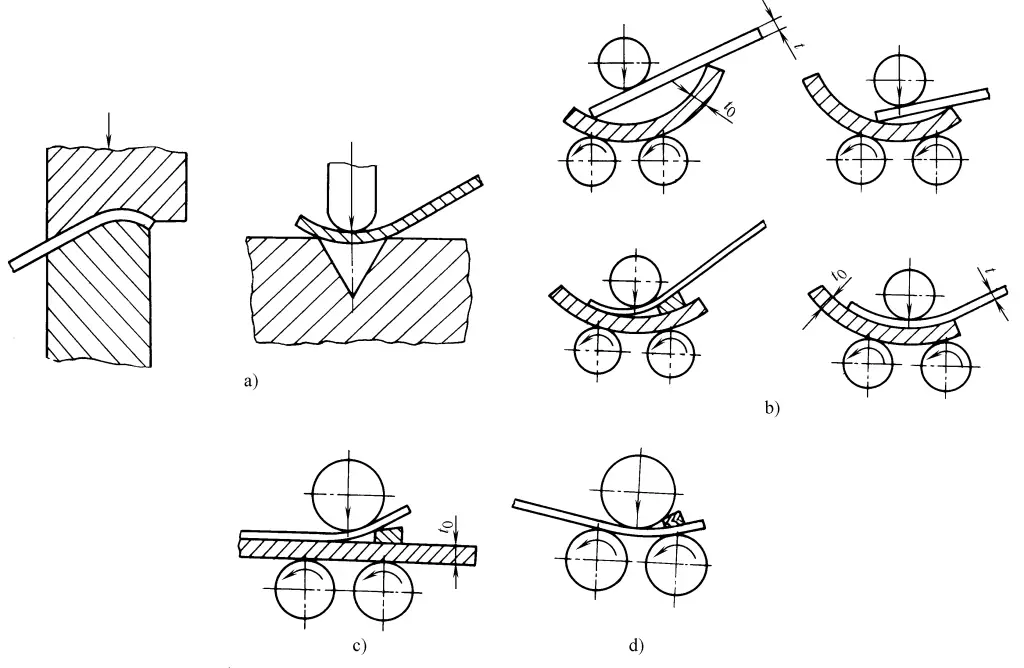
a) Suitable for various plate thicknesses
b) Suitable for t 0 ≥2t, t≤24, not exceeding 60% of the equipment capacity
c) Suitable for t 0 ≥2t, t≥24, not exceeding 60% of the equipment capacity
d) Suitable for thin plates
2. Rolling
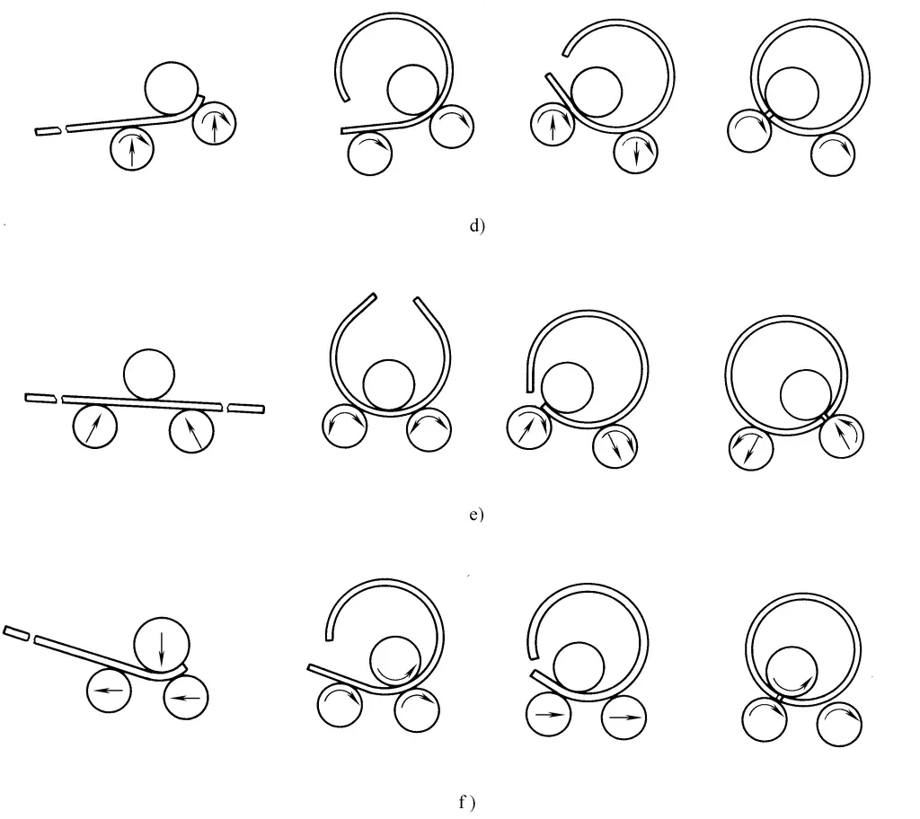
The rolling process of various plate rolling machines is shown in Figure 4.
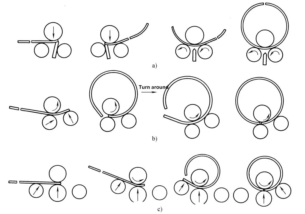
a) Symmetrical three-roll plate rolling machine with bending edge pad
b) Asymmetrical three-roll plate rolling machine
c) Four-roller plate bending machine
d) Eccentric three-roller plate bending machine
e) Symmetrical lower-adjustment three-roller plate bending machine
f) Horizontal lower-adjustment three-roller plate bending machine
3. Correcting roundness
Adjust the roller to the required maximum straightening curvature position, roll 1-2 circles to make the entire circle curvature uniform, then gradually remove the load, allowing the workpiece to be rolled multiple times under gradually reduced straightening load to straighten.
III. Cone rolling
To roll a conical body, the plate blank needs to be pre-cut into its unfolded fan shape. By making the upper roller and side roller intersect at an angle (not parallel) and keeping the roller pressure line always coincident with the generatrix of the fan-shaped blank, a cone can be rolled.
In the common methods of bending cones, the more accurate ones include the small opening deceleration method, the dual-speed four-roller rolling method, and the rotary feeding method, while the approximate methods include the segmented rolling method and the rectangular feeding method.
1. Rectangular feeding method
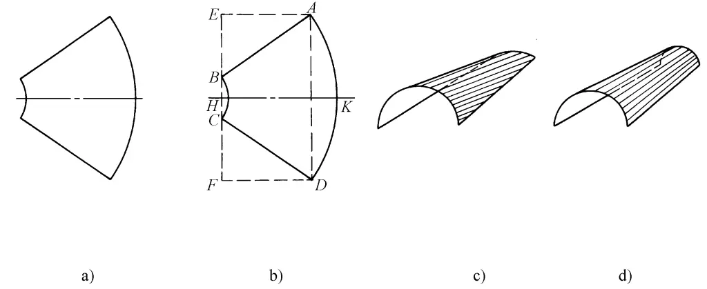
Composed of three cylinders to approximate a conical surface (see Figure 5): first, roll into a cylindrical shape c with the upper roller parallel to the HK line, then bend both sides with the upper roller parallel to the AB and CD lines respectively to obtain an approximate conical surface d.
2. Zonal rolling method
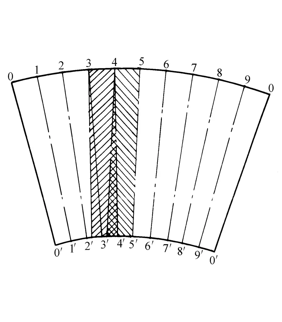
As shown in Figure 6, the movement across zones is used to approximate speed adjustment. The steps are:
(1) Roll bending with the upper roller aligned with the 5-5′ line until the larger end reaches 4;
(2) Roll bending with the upper roller aligned with the 4-4′ line until the larger end reaches 3;
(3) Follow the above steps to bend each zone.
3. Rotational feeding method
As shown in Figure 7, guide wheels are added to the larger and smaller edges of the blank to rotate and feed it, making the roll pressing line basically coincide with the generatrix.
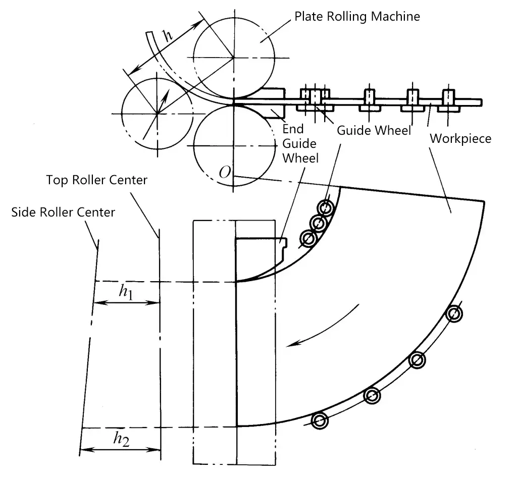
4. Small end deceleration method
As shown in Figure 8, a friction deceleration device is added at the small end of the blank, increasing the resistance of the small end feed and decelerating.
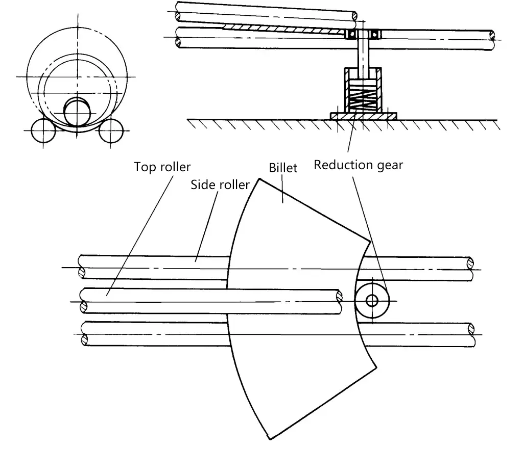
5. Dual-speed Four-roller Bending Method
(see Figure 9)
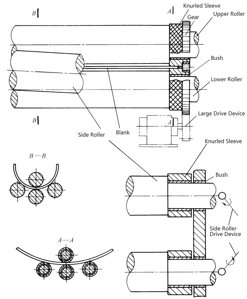
The upper, lower, and side rollers of the four-roller plate bending machine are driven by two sets of transmission devices, with the upper and lower rollers driving the larger diameter of the blank and the side rollers driving the smaller diameter. By appropriately adjusting the speed of the transmission devices, the angular velocity of the larger and smaller diameters being fed in is made the same, resulting in a more accurate cone shape.
IV. Two-axis Bending (Two-roller Plate Bending)
The two-roller plate bending machine works with one rigid roller and one elastic roller. When the steel roller presses into the elastic roller, which has a certain hardness and high elasticity, the elastic roller deforms radially inward, and the plate material fed between the two rollers is bent by the rebound force of the elastic material deformation, driving the elastic roller, thus achieving continuous bending of the plate material, as shown in Figure 10. The elastic roller is made of polyurethane rubber, with a hardness of 85~95HS Shore hardness.
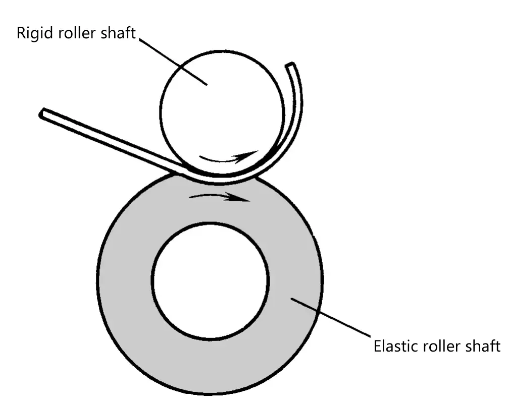
The relationship between the roller shaft depression amount and the diameter of the workpiece is shown in Figure 11.
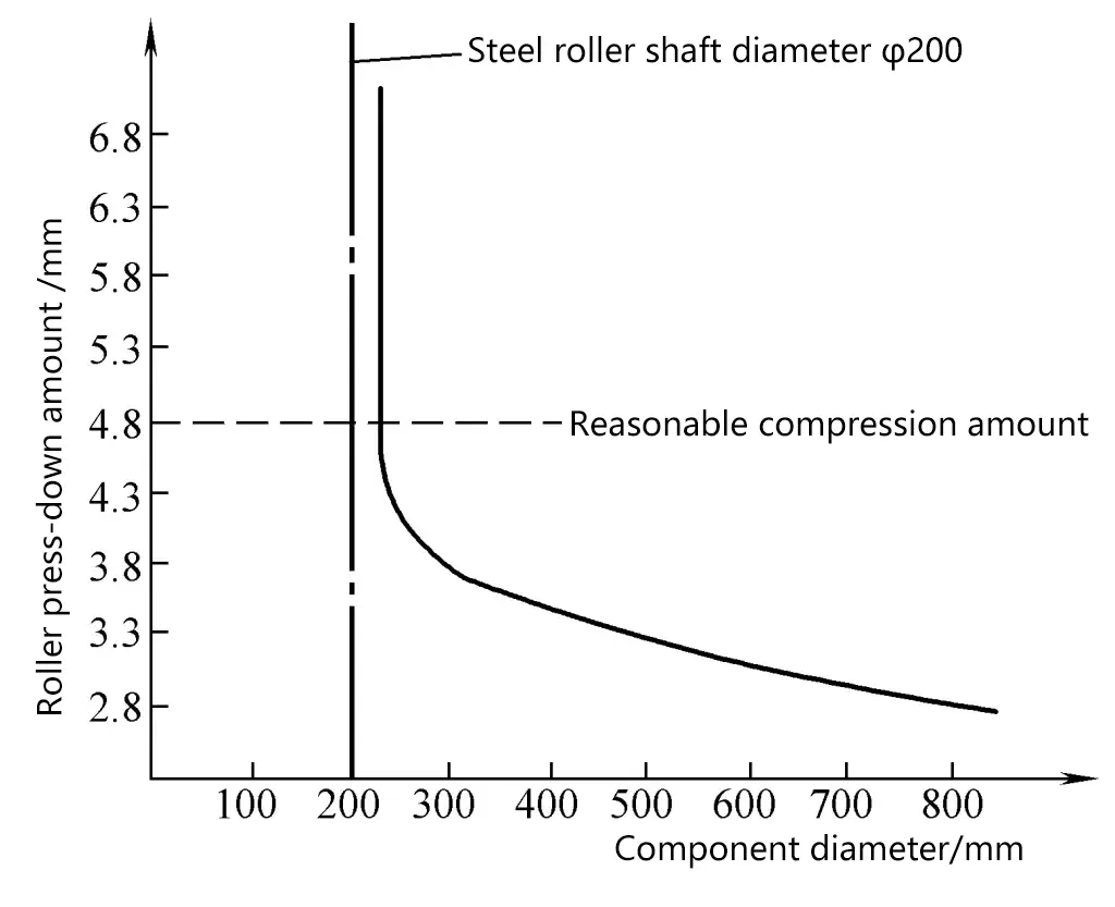
When the depression amount reaches a certain critical value, even if the depression amount is increased, the change in the diameter of the workpiece is very small. Therefore, a deformation amount slightly more than the critical depression amount is considered a reasonable depression amount. When the depression amount is less than the critical value, the diameter size of the workpiece is not stable, so it is generally not used.
To change the diameter of the part, a guide roller of appropriate diameter can be sleeved on the rigid roller shaft for roll bending processing, as shown in Figure 12.
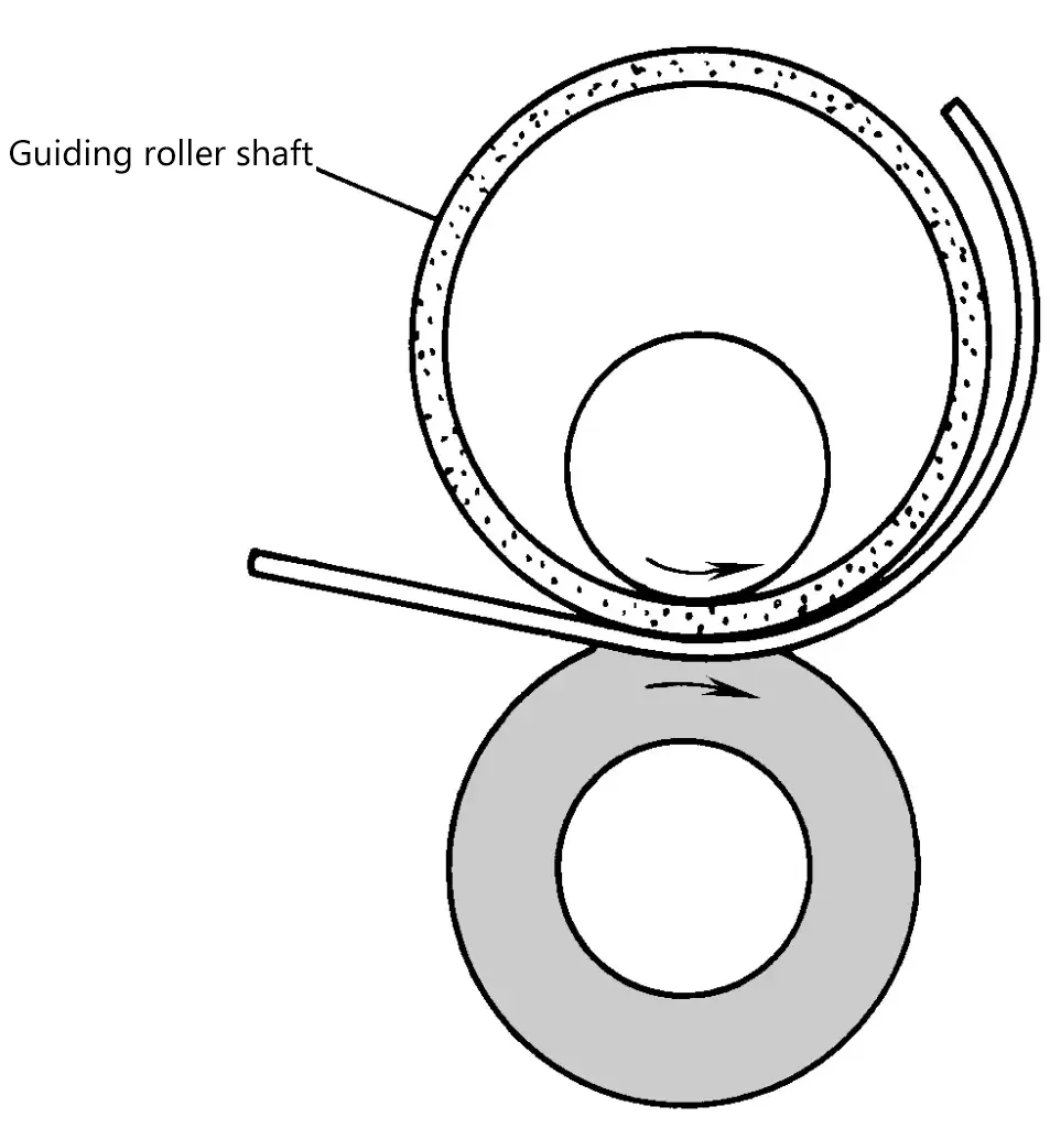
The actual operation of bending plate parts on a two-roll plate bending machine can be carried out in two ways: for materials with good plasticity (δ>30%) or thin plates (thickness less than 1.5~4mm), the part can be bent in one go; for materials with poor plasticity or thick plates, the pressure of the steel rollers should be increased to pre-bend the inlet and outlet ends of the plate, and then bend the part in one or several times (intermediate annealing can be performed).
The main advantages of two-roll plate bending compared to three-roll or four-roll plate bending are:
(1) High production efficiency. Generally, it can reach 100~350 pieces/hour, and up to 1000 pieces/hour.
(2) High precision of parts and good surface quality.
(3) Greatly reduces the straight sections at the entering and exiting ends of the roll bending parts. The straight section of thin plates will not exceed the material thickness, and the straight section of thick plates will also not exceed four times the material thickness. Therefore, it is generally not necessary to pre-bend the ends before roll bending.
(4) Even if the blank is processed by punching, notching, undulating forming, etc., it will not cause fractures and irregular bending.
The disadvantages of two-roll plate bending are:
(1) Since a guide roller needs to be made for every change in the diameter of the part relative to its diameter, it is not suitable for multi-variety small batch production.
(2) The dimensions of the parts are subject to certain restrictions. The processing range of the existing two-roll bending machine is: plate thickness within 6.3mm (soft steel), bending diameter from ϕ76 to ϕ460mm.

