I. Basic Process Knowledge
1. Principles and Functions of Scraping
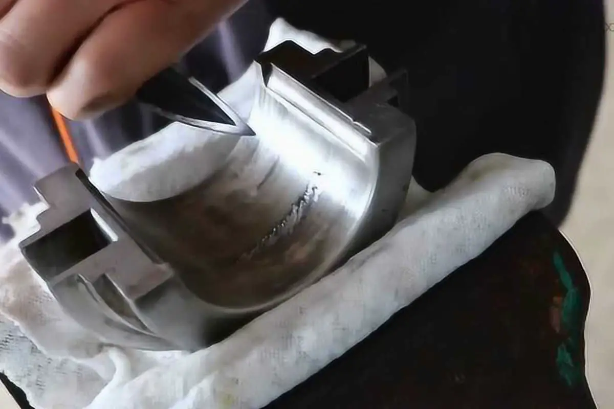
As shown in Figure 1, scraping is the operation of using a scraper to remove a very thin layer of metal from the surface of a workpiece to further improve the precision of the processed surface.
The basic method of scraping is mutual scraping, which involves using standard tools or workpieces that match the scraped surface to show the positions and distributions of higher metal layers on the processed surface. The operator applies pressure and pushing force on the scraper to remove these higher metal layers, continually refining through mutual scraping until the required processing precision is achieved.
Scraping is generally divided into three stages: rough scraping, fine scraping, and precision scraping. To achieve the required processing precision, it often involves repeated mutual scraping and refinement. Through scraping, the shape precision, position precision, and contact precision of the processed surfaces are further improved, surface roughness is reduced, and the oil retention and sealing performance of the assembly are greatly enhanced.

2. Scraping Tools
(1) Developer
Before mutual scraping, to understand the size and location of workpiece errors, a thin and even layer of colored paint must be applied to the surface to be scraped. Through mutual scraping, the raised areas are shown, as illustrated in Figure 2, and then removed with a scraper.

Common developers include red lead powder and Prussian blue. For red lead powder, it is mixed with machine oil and tallow. This developer does not reflect light, shows spots clearly, is inexpensive, and is widely used on cast iron and steel parts. Prussian blue oil is made by mixing Prussian blue powder with castor oil and machine oil. It appears deep blue with small, clear spots, making it ideal for precision scraping and non-ferrous metal parts.
(2) Common Scraping Lapping and Inspection Tools
(See Table 1)
Table 1: Common Scraping Lapping and Inspection Tools
| Name | Illustration | Function | |
| Scraping and Inspection Tools | Standard Flat Plate | 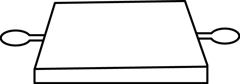 | Mainly used as a reference lapping tool for flat surfaces during scraping; grade 0 and grade 1 flat plates are commonly used. |
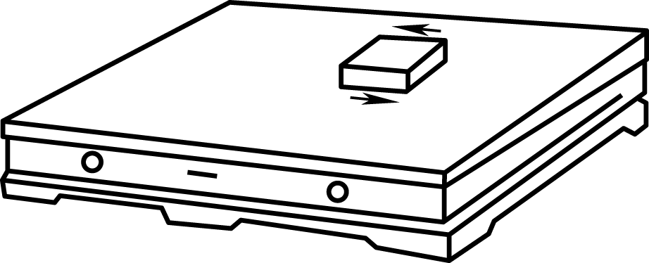 | Used as a reference lapping tool for scraping | ||
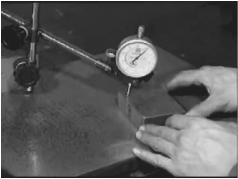 | For inspecting flatness | ||
| Bridge Straightedge |  | Used as a reference lapping tool for coloring points when scraping long and narrow planes | |
| I-Shaped Straightedge | 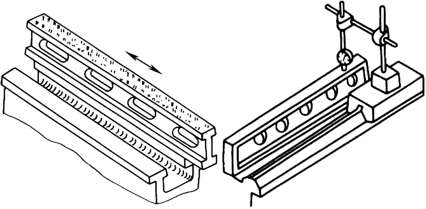 | 1) Used as a reference lapping tool for coloring points when scraping long and narrow planes; 2) For checking the straightness of long and narrow guides | |
| Angle Straightedge | 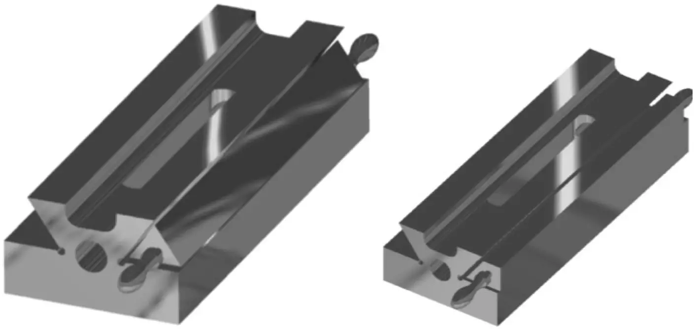 | Used as a reference lapping tool for coloring points when scraping angled (e.g., dovetail) long and narrow planes | |
| Inspection Rod | 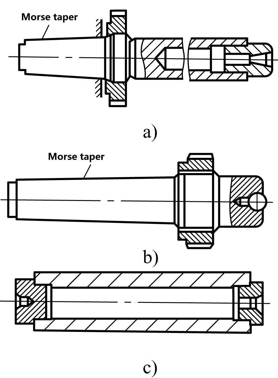 | Mainly used to inspect the radial runout, axial movement, coaxiality, and parallelism of machine tool spindle sleeves and other components | |
(3) Scraper
1) Flat Scraper
① Types of Flat Scrapers
Common flat scrapers are made from either integral scrapers or inlaid head scrapers. Integral scrapers are typically made from alloy tool steel (such as 9SiCr) or spring steel, with the front blade hardened. Inlaid head scrapers have carbide tips inlaid at the front end of the scraper body.
As shown in Figure 3, commonly used flat scrapers can also be divided by shape into hand push flat scrapers, stand scraping flat scrapers, and bent head flat scrapers.
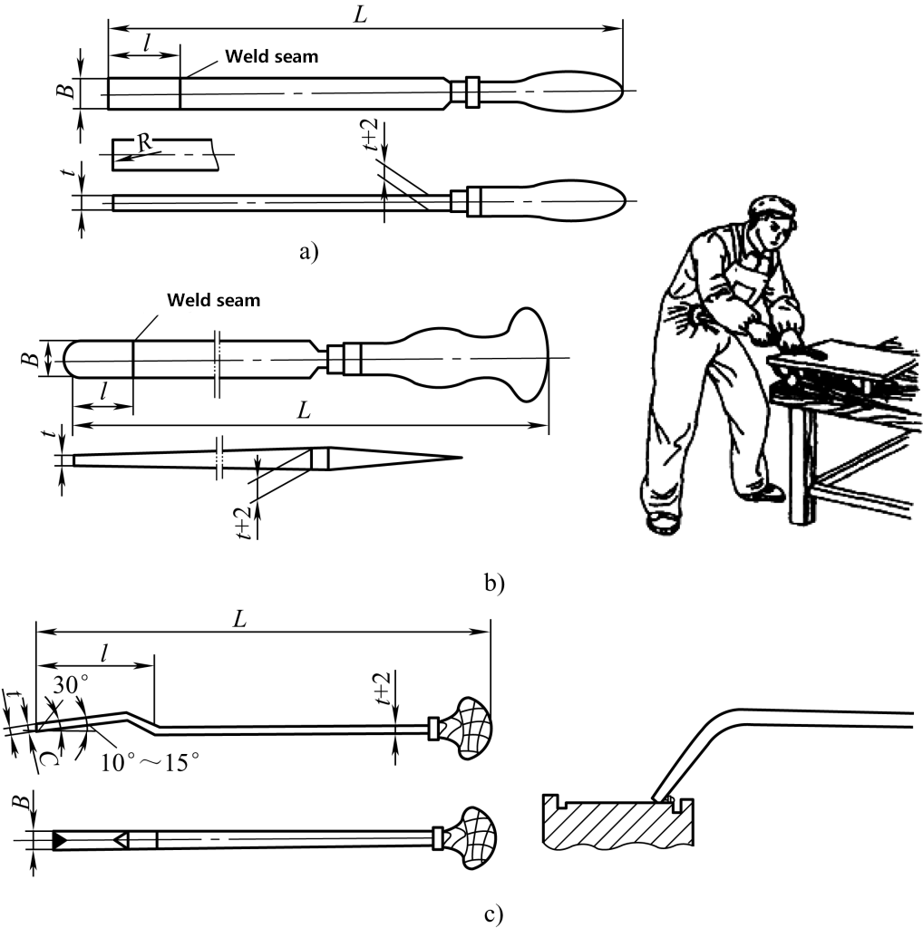
a) Hand Push Flat Scraper
b) Stand Scraping Flat Scraper
c) Bent Head Flat Scraper and Step Pull Scraping
② Shape and wedge angle of the plane scraper’s cutting head
The shape and wedge angle of the plane scraper’s cutting head are shown in Figure 4.
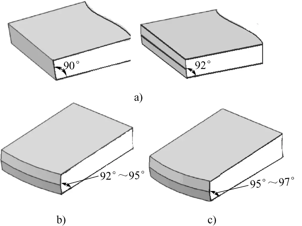
a) Wedge angle of the rough plane scraper
b) Wedge angle of the fine plane scraper
c) Wedge angle of the precision plane scraper
- As shown in Figure 4a, the wedge angle of the rough plane scraper (the angle between the front and rear faces of the scraper) is 90°–92°, and the cutting edge is straight.
- As shown in Figure 4b, the wedge angle of the fine plane scraper is generally around 95°, and the cutting edge has a slight arc.
- As shown in Figure 4c, the wedge angle of the precision plane scraper is generally around 97°, and the curvature of the cutting edge arc is greater than that of the fine scraper.
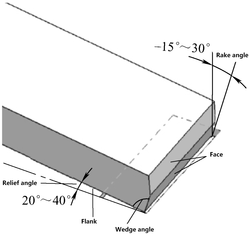
③ Cutting angle of the plane scraper
As shown in Figure 5, during the scraping process, the rake angle γ generally varies between -15° and 35°, while the clearance angle α generally varies between 20° and 40°. Due to the small rake angle of the scraper, it exerts a pushing and polishing effect on the workpiece surface, thereby reducing the surface roughness value of the machined surface.
2) Curved surface scraper
Curved surface scrapers are mainly used for scraping inner curved surfaces, such as various types of sliding bearings. Sometimes, they are also used to scrape off the burrs inside holes.
① Types of curved surface scrapers
Triangular scrapers and snakehead scrapers. Triangular scrapers and snakehead scrapers are mainly used for scraping general inner curved surfaces and removing burrs at hole openings. Figure 6 shows their structural forms.
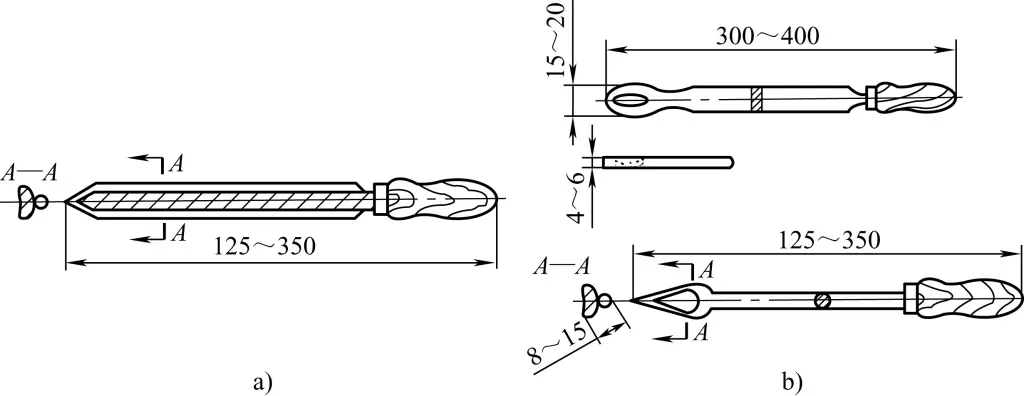
a) Structural form of the triangular scraper
b) Structural form of the snakehead scraper
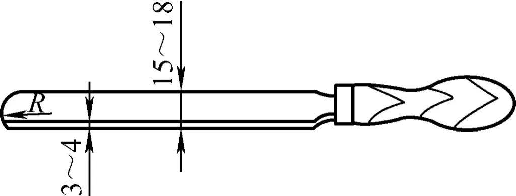
Semi-circular head scraper. As shown in Figure 7, the cutting edge part of the semi-circular head scraper is semi-circular, making it difficult to produce angular points during scraping. It is suitable for scraping split bearings, etc. The cutting edge size R of the semi-circular head scraper can be ground according to the radius size of the curved surface being scraped.
Willow Leaf Scraper. As shown in Figure 8, the willow leaf scraper has two blades: the tip is for fine scraping, and the rear is for heavy scraping. It is suitable for scraping copper sleeves and split bearings.
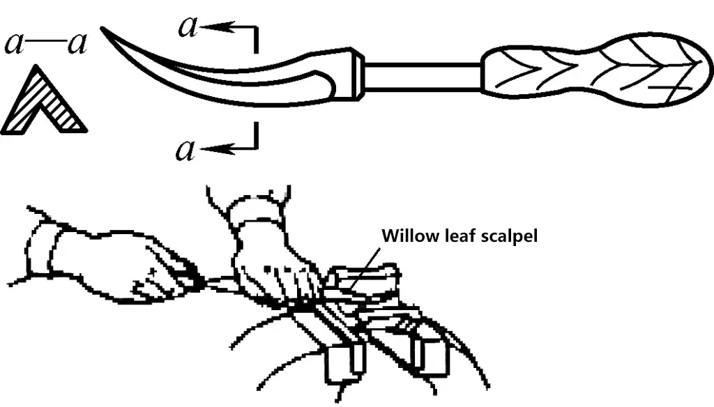
Cutting Rake Angle of Curved Scraper. Figure 9 shows the cutting form of the curved scraper. When using a positive rake or neutral rake for scraping, the chips are thicker and the tool marks are deeper, suitable for rough scraping and scraping soft bearing alloys, such as soft Babbitt metal.

When using a negative rake for scraping, the chips are thinner, which can reduce chatter marks during scraping and thus lower the surface roughness value of the processed surface. However, due to the serious extrusion scraping phenomenon at the blade edge, it is prone to cause tool biting and scraping traces when scraping low-hardness materials such as tin-based bearing alloys. Therefore, it is usually used for high-hardness copper-based bearing alloys or for finishing during the final fine scraping.
When using a negative rake to finish scrape the inside curved surface of low-hardness bearings, the radial pressure on the scraper should be minimized.
II. Basic Operational Skills
1. Grinding the Scraper Blade
(1) Grinding the Plane Scraper Blade
1) Requirements for Grinding the Plane Scraper Blade
The overall requirements for grinding the plane scraper blade are:
- The two rear faces of the scraper blade should be flat and smooth, without any convex or concave irregularities.
- The two front faces and the cutting edges of the scraper blade should be symmetrical to the central axis, flat, and smooth, without any convex or concave irregularities, and there should be no arc surface in the thickness direction of the blade.
- According to different application scenarios, correctly grind the wedge angle of the scraper blade.
- When grinding scraper blades made of tool steel on a grinding wheel, dip the blade in water for cooling during the grinding process to prevent the blade head from being annealed. For carbide-tipped scraper blades, do not dip the carbide part in water during grinding to prevent the blade edge from cracking.
2) Method for Grinding the Plane Scraper Blade
① Grinding the rear face of the scraper blade (see Figure 10)
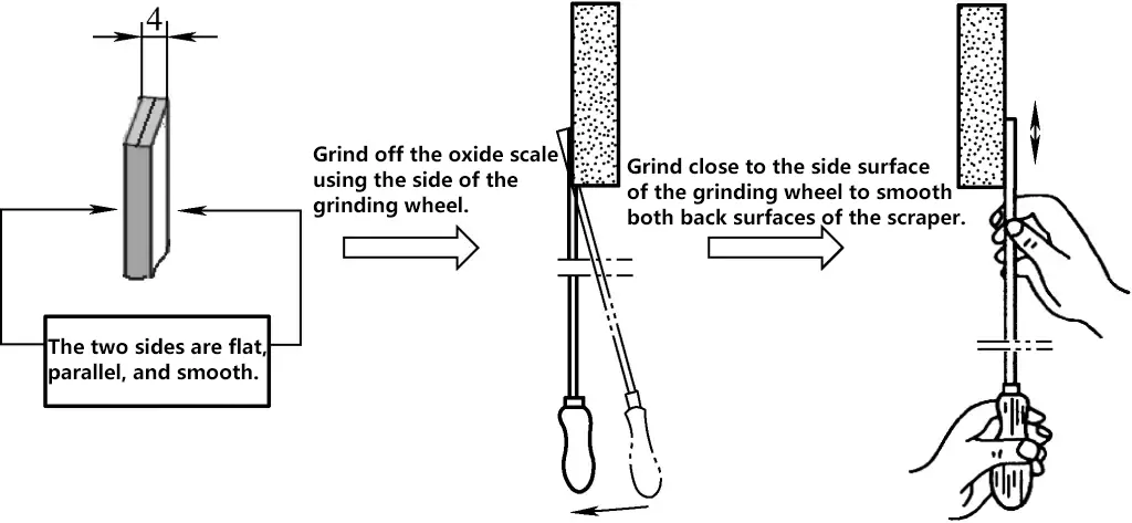
② Rough grinding of the front face and cutting edge of the scraper blade
As shown in Figure 11, when rough grinding the front face and cutting edge of the scraper blade, place the tip of the blade steadily on the edge of the grinding wheel, and the position should be slightly higher than the center of the grinding wheel.
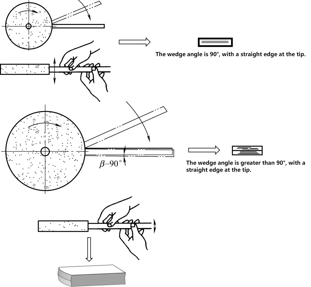
To prevent vigorous vibration when the tip touches the edge of the grinding wheel, first tilt the scraper blade at an angle to make light contact with the grinding wheel, then slowly move the blade from top to bottom to the required position. If the required wedge angle is 90°, place the blade horizontally; if the required wedge angle is greater than 90°, tilt the blade when grinding.
After grinding one side, use the front hand (the hand closest to the edge of the grinding wheel) as a fulcrum to rotate the blade 180° and grind the other side, making both front faces symmetrical.
When grinding the cutting edge at the tip, move the blade smoothly from side to side. If a straight cutting edge is required (for rough scraping blades), move the blade along a straight line. If a rounded cutting edge is required (for fine and finishing scraping blades), slightly swing the blade, adjusting the swing amount according to the curvature of the cutting edge.
3) Fine Grinding of the Plane Scraper Blade
After rough grinding the scraper blade on the grinding wheel, there will be significant microscopic unevenness on the cutting edge. If used directly for scraping, the tool marks will be deeper and it will be prone to chipping, causing scraping threads. Therefore, after rough grinding, the scraper blade should be fine-ground on an oil stone.
① Fine Grinding the Rear Face of the Scraper Blade
When fine grinding the rear face of the scraper blade on an oil stone, first check the flatness of the oil stone surface. If there are any concave or convex irregularities in the middle of the oil stone, do not use it. Apply clean machine oil on the oil stone, then press the rear face of the scraper blade tightly against the oil stone surface, and move the scraper blade horizontally and evenly with both hands simultaneously. After fine grinding for a period, use a steel ruler to check if the rear face of the scraper blade is ground flat.
As shown in Figure 12, Figure 12a is the correct method for fine grinding the rear face of the scraper blade. If ground as shown in Figure 12b, the rear face of the scraper blade is easily lifted or tilted horizontally, which will cause the rear face to be ground unevenly or produce an arc surface.
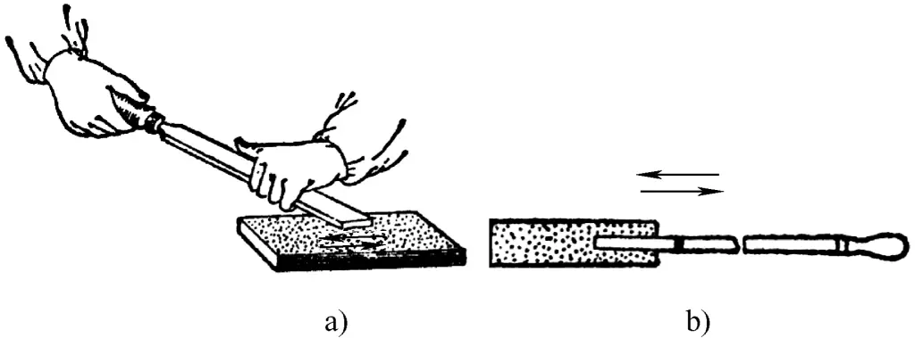
a) Correct Method for Fine Grinding the Rear Face
b) Incorrect Method for Fine Grinding the Rear Face
② Fine Grinding the Front Face and Cutting Edge of the Scraper Blade
The fine grinding of the front face and cutting edge of the scraper blade is shown in Figure 13.
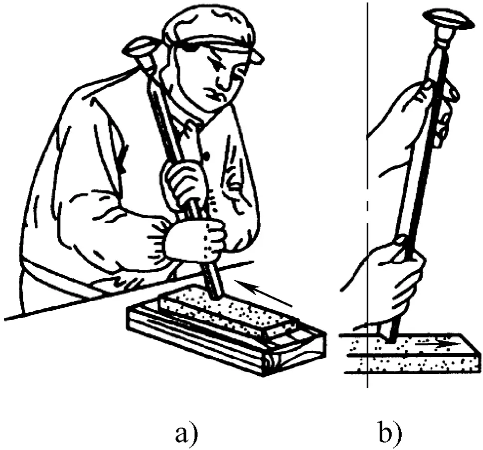
Method One: As shown in Figure 13a, support the upper part of the scraper blade on the shoulder, hold the blade body with both hands, move the scraper blade from front to back, then slightly lift the blade and move it from front to back again. Repeat this process and check the flatness of the front face.
Note that if the fine grinding wedge angle is 90°, keep the blade body perpendicular to the oil stone during grinding, meaning the front face should be tightly pressed against the oil stone surface. If the fine grinding wedge angle is greater than 90°, tilt the blade body accordingly.
Method Two: As shown in Figure 13b, hold the blade body with both hands and press the front face of the scraper blade tightly against the oil stone surface. Apply downward pressure while pushing the scraper blade forward, lift the scraper blade slightly when reaching the front end of the oil stone, and then pull it back. Repeat the grinding process.
As mentioned above, if the fine grinding wedge angle is 90°, the blade body should be kept perpendicular to the oil stone during grinding. If the fine grinding wedge angle is greater than 90°, the blade body should be tilted accordingly.
It is particularly emphasized that no matter which grinding method is used, when grinding, both hands should move the scraper blade simultaneously. Do not use one hand as a fulcrum and the other hand to swing the scraper blade. If grinding this way, the front face of the scraper blade will develop an arc surface, affecting the sharpness of the blade.
(2) Grinding the Curved Scraper Blade
1) Coarse Grinding of Curved Scrapers
Currently, curved scrapers are basically formed scrapers. The main purpose of coarse grinding curved scrapers is to trim the worn curved inner grooves and to make the blade edge curve continuous by grinding the arc surface, thus eliminating blade edge chipping.
① Coarse Grinding of Triangular Scrapers
The method of grinding the arc surface of the triangular scraper head on the grinding wheel machine is shown in Figure 14.
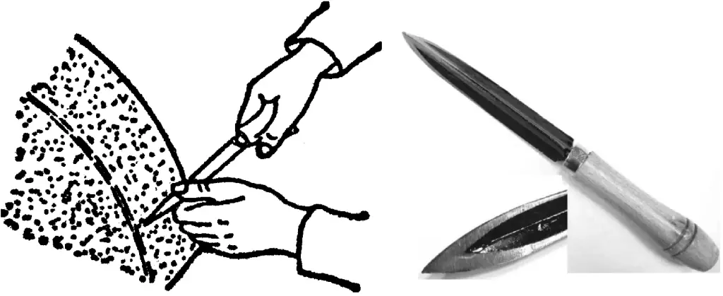
Lightly press the scraper in a horizontal position on the outer circular arc surface of the grinding wheel, moving back and forth according to the blade arc, so that the intersection lines of the three surfaces form an arc-shaped blade edge.
The method of grinding the inner arc grooves of triangular scrapers on the grinding wheel machine is shown in Figure 15.
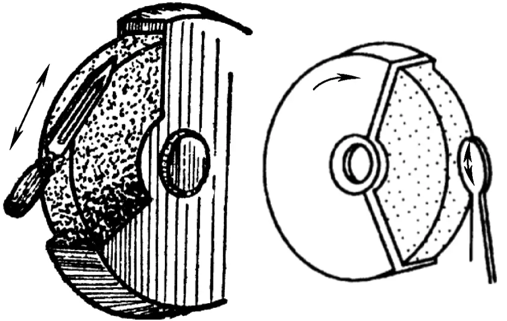
When grinding the inner arc grooves, place the center of the scraper inner arc groove on the edge of the grinding wheel, moving up and down to control the groove length, and moving left and right to control the groove width. The knife groove should be located in the middle of the two blades.
② Coarse Grinding of Snakehead Scrapers
Place the snakehead scraper on the central plane of the grinding wheel, moving up and down along the outer circular arc surface of the grinding wheel to shape the arc. Grind the groove on the edge of the grinding wheel, leaving a 2-3mm margin.
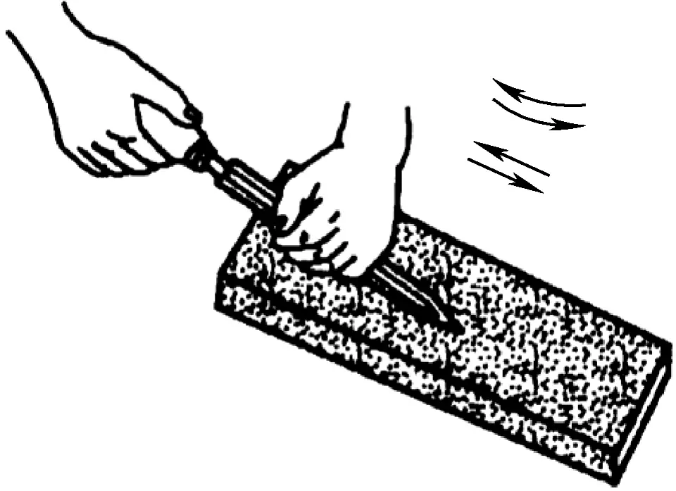
2) Fine Grinding of Curved Scrapers
As shown in Figure 16, fine grinding of curved scrapers is also done on an oil stone. During fine grinding, move the scraper back and forth along the length of the oil stone, oscillating up and down according to the blade arc, until the grinding marks on the three blade edges are removed, the arc surface is smooth, and the blade edge is sharp.
For a smoother arc surface and sharper blade edge, polishing paste can also be applied on the lapping plate for grinding the blade edge.
2. Scraping Process
(1) Plane Scraping Process
1) Coloring and Lapping Requirements
As previously mentioned, to display the positions of local high points on the surface, display agent should be applied to the scraped surface before scraping, and the surface should be lapped with standard tools or matching parts. The high points can be determined by the black marks displayed.
① Display Agent and Application Requirements
The proportion of the display agent should be appropriate, not too thin or too thick. If too thin, it will be too oily and black marks will appear in the lower areas during lapping, making it difficult to determine the true high points; if too thick, the resistance during lapping will be too high, causing bouncing phenomena and affecting the lapping quality. Usually, for rough scraping, the display agent should be thinner; for fine scraping, it should be thicker.
The display agent should not be applied too thick or too thin. If the layer is too thick, black marks will also appear in the lower areas, leading to false results; if too thin, the displayed points will not be clear, making it difficult to find the high points during scraping.
Before applying the display agent, the surfaces of the lapping tool and the scraped surface should be wiped clean and kept dry. If there are contaminants on the surface, black marks will appear after lapping, but these will not indicate the true high points, leading to incorrect operations during scraping.
When the scraping reaches the fine scraping stage, clear and prominent points are required. The display agent can be applied to the reference plane of the lapping tool for this purpose.
② Lapping Points Precautions
Correct lapping methods can reveal the real high points on the scraped surface and avoid false lapping points. Therefore, during lapping, the standard tools or matching parts should not extend beyond the ends of the scraped surface by more than one-third of the workpiece length; also, the pressure applied to the tools or parts should not be too high, and the lapping time should not be too long.
2) Scraping Process
① Rough Scraping
As shown in Figure 17, the main objective of rough scraping with a rough scraper is to remove the oxide layer on the metal surface and to meet the flatness technical requirements. Typically, for mating surfaces (such as gearbox mating surfaces) or moving subsystem guideways (such as horizontal lathe guideways), the flatness after rough scraping should be within 0.02mm. After lapping with matching parts or standard inspection tools, the high points should be evenly distributed without a central high and surrounding low phenomenon.
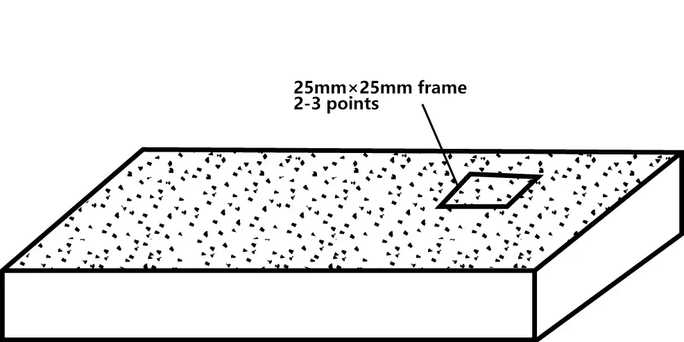
Inspect with a standard 25mm×25mm square frame; 2-3 points should be displayed. To meet this scraping technical requirement, the high points (black and shiny spots shown after lapping) should be heavily scraped.
The edge of the rough scraper is generally straight, creating wider and longer scraping marks, known as the long scraping method, where the scraping marks can overlap. When scraping multiple times, the scraping marks should be perpendicular to each other.
② Scraping with Fine Scraper
Further increase the number of contact points on the basis of rough scraping. During scraping, use the short scraping method with shorter and narrower scraping marks. When scraping multiple times, each scraping direction should be consistent, with the latter scraping marks crossing the previous ones by 45° to 60°.
To improve the efficiency of fine scraping, high points (black and shiny spots) should be heavily scraped during scraping, and the surrounding area of these high points should also be scraped to reveal the sub-high points. Inspect with a standard 25mm×25mm square frame; 12-15 points should be displayed.
③ Fine Scraping
On the basis of fine scraping, further use a fine scraper to improve the flatness of the processed part surface and the contact accuracy of the matching parts.
During fine scraping, aim the scraper at the high points, removing the largest and brightest points, breaking up medium-sized bright points, and leaving small points unscraped; the scraping marks become shorter and narrower, requiring that the scraping flowers are uniform in size and cross neatly. Inspect with a standard 25mm×25mm square frame; more than 20 points should be displayed.
(2) Curved Surface Scraping Process
In the manufacturing and major repairs of general equipment, curved surface scraping mainly refers to the scraping of sliding bearings, the most common being the scraping of integral radial sliding bearings (sleeves), split radial sliding bearings (split bushings), inner conical outer cylindrical sliding bearings (e.g., lathe bushings), and three-segment fan-shaped bushings (e.g., grinder bushings).
In addition to being similar to the plane scraping process mentioned above, the following points should also be noted for curved surface scraping:
1) Preparation for Scraping
① Understand in detail the technical requirements for installing the bearings, such as the clearance requirements after sleeve installation; installation requirements for split bushings and the method for adjusting the bearing clearance with shims; installation requirements and precision adjustment methods for inner conical outer cylindrical sliding bushings; alignment methods for fan-shaped bushings, etc.
② Understand the operational accuracy requirements of the equipment, use suitable inspection tools to check the relevant geometric accuracy, and make detailed records.
To meet the operational accuracy requirements of the equipment, the inner and outer surfaces of sliding bearings are generally ground, and the geometric accuracy (such as roundness, coaxiality, parallelism, perpendicularity with relative motion parts, etc.) is already close to the required precision. Necessary inspections clarify the purpose of scraping and the allowance for scraping, facilitating the formulation of the scraping plan.
2) Preparation of Tools and Equipment
In addition to preparing scrapers and various precision measuring tools, special attention should be given to preparing necessary jigs and clamping tools (molds) for curved surface scraping.
In certain situations (such as when the shaft paired with the bearing is heavy or inconveniently located for scraping), a standard shaft with the same diameter as the bearing can be used as a “dummy shaft” during rough scraping. The dummy shaft typically undergoes precision grinding. When scraping the bearing, it can be done on this dummy shaft.
Unlike flat surface scraping, the method of clamping the bearing directly affects the quality of the scraping. If the bearing is not properly placed or clamped during scraping, it will deform, severely impacting the quality. Figure 18 shows commonly used jigs for scraping.
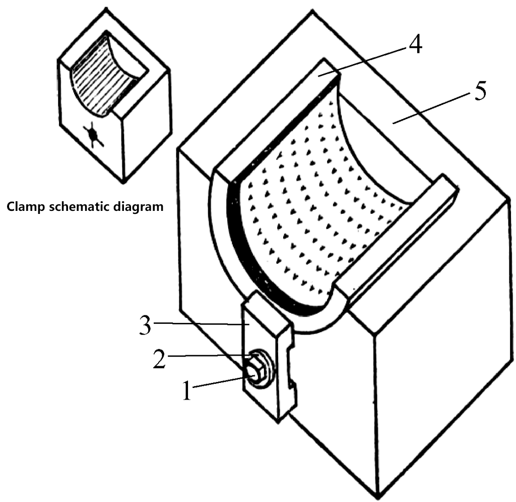
1—Screw
2—Washer
3—Pressure Plate
4—Workpiece
5—Clamp Body
3) Typical bearing scraping process
① Scraping process for split-type bearings
The structure of split-type sliding bearings is shown in Figure 19.
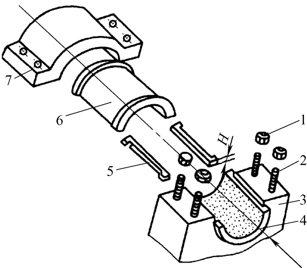
1—Nut
2—Double-ended Stud
3—Bearing Housing
4—Lower Bearing
5—Adjustment Shim
6—Upper Bearing
7—Bearing Cap
Depending on the performance requirements of the equipment, the precision required for bearing scraping varies. For heavy machinery with high spindle rotation precision requirements, the shaft and bearing must have good contact accuracy to increase transmission rigidity, reduce vibration, and improve transmission smoothness. Additionally, there must be strict top and side clearances between the shaft and bearing to form a hydrodynamic oil film. Therefore, scraping should consider the contact accuracy between the shaft and bearing (contact areas, contact surface, and number of contact points) and the clearances.
Trimming the bearing back. The back of a split bearing should have good contact with the bearing housing hole. Otherwise, during operation, under the force of the journal, vibration or even deformation of the bearing may occur. Hence, if it does not meet requirements upon inspection, the bearing back should be re-scraped using the housing hole as a reference.
Rough scraping of the bearing hole. The goal of rough scraping the bearing hole is to eliminate deformation of the bearing inner hole, correct the contact area between the bearing and the shaft, and increase the contact area. When rough scraping the bearing hole, the bearing can be clamped with a soft rubber pad in a vise for scraping. After scraping, the bearing can be fitted onto the matching shaft for contact marking, or it can be assembled into the bearing housing and scraped using the matching shaft.
Precautions when using a shaft to mark the bearing after installing it into the bearing housing are:
- Apply developer on the inner surfaces of the upper and lower bearings.
- Assemble the mating shaft, upper bearing, double-ended stud, and bearing cap.
- Tighten the nuts. During initial rough scraping, if the nuts are overly tightened, the shaft will have difficulty rotating. Therefore, at the beginning of rough scraping, the nuts should be lightly tightened while rotating the mating shaft, adjusting the thickness of the shims to ensure the shaft rotates with appropriate tightness.
- Similar to flat surface scraping, during rough scraping, the focus should be on the darker and shinier areas that appear on the inner surface of the bearing after preliminary marking.
- After rough scraping for a while, use a feeler gauge to measure the top and side clearances between the shaft and bearing. When the contact points distribution is uniform (4–7 points per 25mm×25mm), the top and side clearances should also be close to the equipment’s technical requirements.
- Specifically, in heavy-duty machines, to prevent the spindle from seizing, the lower bearing at the extended end of the spindle can be scraped slightly lower.
Fine scraping of the bearing hole. The aim of fine scraping the inner hole of the bearing is: firstly, to increase the number of contact points between the shaft and the bearing inner hole (10–15 points per 25mm×25mm) with the points becoming smaller and evenly distributed; secondly, after fine scraping, use a feeler gauge to measure the top and side clearances of the shaft to meet the equipment’s specified requirements.
During the fine scraping process, the thickness of shims between the upper and lower bearings should be reduced progressively; the tightening force of the nuts after assembling the bearing into the housing hole should progressively increase. However, the force should not be excessive (it should be possible to rotate the shaft manually), to prevent creating “false points” during marking.
Similar to flat surface scraping, during scraping, the tool marks should be crossed; the dark and shiny points should be heavily scraped, while the areas around the high points should be lightly scraped to allow the next higher points to increasingly appear.
② Scraping process for inner pillar outer taper sliding bearings
Firstly, the order of scraping.
As shown in Figure 20a, inner pillar outer taper sliding bearings are commonly used for machine tool spindle drives. The scraping repair sequence for inner pillar outer taper sliding bearings is to first use the matching shaft as a jig to scrape the bearing inner hole to meet rotational precision requirements; then scrape the outer taper of the bearing to fit the spindle box hole (for new bearings, the outer taper surface should be scraped using the machine base hole as a reference) with a display of 4 points per 25mm.
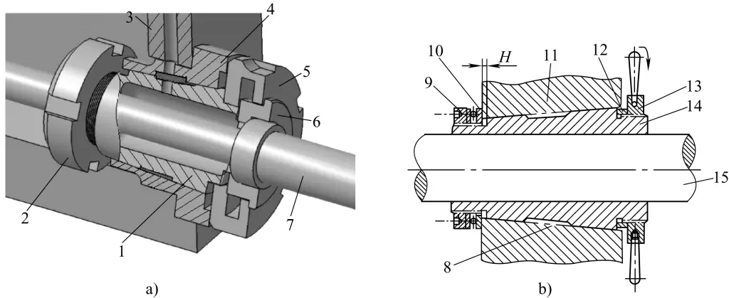
1—Inner Bearing Sleeve
2—Rear Nut
3—Bearing Housing Hole
4—Outer Bearing Sleeve
5—Front Nut
6—Adjustment Sleeve
7—Shaft
8—Contact Mark Points
9—Nut
10—Thrust Ball Bearing
11—Spindle Box
12—Bushing
13—Spanner Nut
14—Bearing
15—Main Spindle
As shown in figure 20b, after the outer conical surface and the inner hole of the casing have been scraped, remove the spanner nut and bushing, lock the bearing in the hole of the spindle box, and then slightly scrape the inner hole of the bearing to fit the spindle.
Then, the technical requirements for scraping the inner hole.
First, to adapt to the characteristics of high-speed operation of the machine tool, after scraping the inner hole, the contact points at both ends of the bearing should be hard and dense, while the contact points in the middle of the bearing hole can be softer and sparser. This easily establishes an oil wedge, making the shaft stabilize during operation. After precision scraping the inner hole, there should be 14 to 17 contact points within 25mm at both ends.
Second, to adapt to the characteristics of heavy-load operation of the machine tool, the contact points on the bearing load surface should be appropriately dense to increase its wear resistance and leave a certain margin for the sinking of the spindle after wear. After scraping the spindle bearing hole of the lathe, the contact points usually present a “diamond” distribution.
③ Precautions for scraping the inner hole.
- If both the front and rear are bearing bush structures, then the front and rear bearings must be scraped simultaneously to ensure their coaxiality.
- When scraping the contact points, rotate the shaft 3 to 5 turns in the same direction as the spindle rotation. Then, pull out the shaft, remove the bearing, and scrape the spots from large patches into chain shapes, until they become scattered spots.
- If the rear bearing is a rolling bearing, an iron sleeve should be made to replace the rolling bearing as a centering sleeve.
- When finally fine scraping the bearing hole, adjacent knife marks should be cross-scraped for every two passes. Once the spots become even, gradually lighten and shorten the knife marks, and the spots should be in the shape of small quadrilaterals or polygons to avoid long strip shapes.
3. Basic techniques for scraping
(1) Flat surface scraping
1) Basic process for flat surface scraping
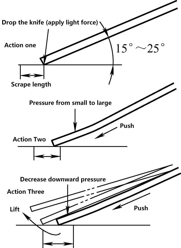
The basic process for flat surface scraping mainly includes the steps of lowering the knife, pressing the knife, pushing the knife, and lifting the knife. The time to complete a scraping action is very short, so the actions need to be continuous and completed in one go.
The key techniques for scraping are: gentle knife lowering (no vibration marks, lowering angle of 15°-25°), steady pressing and pushing (no lateral tilt of the scraper, and pressure changes gradually from small to large), and quick knife lifting (no blade marks).
As shown in figure 21, the action process during flat surface scraping.
2) Hand scraping method and push scraping method
① Hand scraping method
As shown in figure 22, the basic skills for hand scraping. During scraping, the right hand typically holds the handle, the left hand grips the blade, and the palm presses against the front end of the scraper about 50mm from the edge.
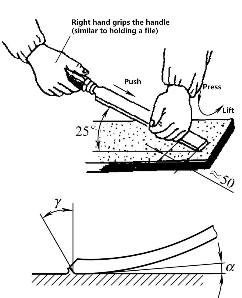
When scraping, after aligning the blade with the scraping area, press the scraper with the left hand, causing slight bending deformation of the blade. Both hands then push the scraper forward for a blade trace length, and quickly lift the scraper. Throughout the process, the phases of pressing, pushing, and lifting are completed in one go. The hand scraping method involves less force and scraping allowance, making it generally suitable for surface finishing of small parts.
② Push scraping method
In the current push scraping operation, the stance and posture are almost the same, with differences in the way the scraper is held and the use of hand force.
Push scraping method one:
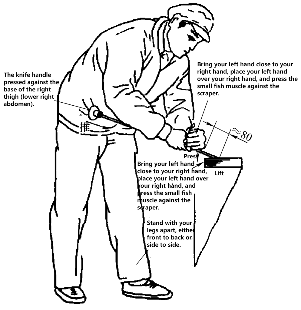
As shown in figure 23, place the handle of the scraper on the right-side muscle of the abdomen, with both hands holding the blade. The left hand is in front, about 80mm from the blade edge (this distance can be adjusted according to the operator’s height). When scraping, both hands press the scraper down (the right hand applying less pressure), using the strength of the legs and hips to push the scraper forward aligned with the contact points.
At the moment after pushing forward, the right hand guides the direction of the scraper, while the left hand quickly lifts the scraper, removing a slice of metal from the surface, completing one push scraping action. This method mainly relies on the left hand to control the scraping pressure, allowing the adjustment of the cutting amount during rough, fine, and precision scraping by adjusting the pressure of the left hand.
Push scraping method two:
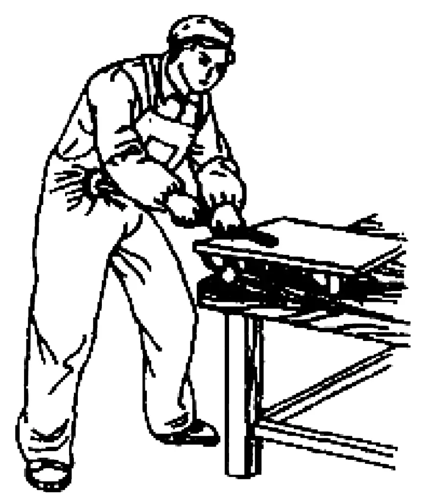
This is the most widely used operation in flat surface scraping. As shown in figure 24, in this method, the right hand holds the scraper, and the left hand is placed on top of the right hand, pressing the scraper. Since both hands are basically close together and apply pressure to a specific point on the scraper, the front end bends considerably, resulting in a larger cutting amount, suitable for rough scraping of soft materials.
After this description, the key techniques for push scraping are summarized as follows:
Stand steadily with feet apart, bend forward at the waist;
Hold the scraper handle with the abdomen (right lower side);
Control the scraper with the right hand, lower the blade gently and flatly;
Press down with the left hand, push forward with waist and legs;
Quickly lift with the right hand, completing the action instantly.
Push scraping method three:
Similar to the above two actions, the difference lies in the changes in the forces applied by both hands on the blade. In this method, the left hand is in front, the right hand is in the back holding the blade, and after aligning the scraper edge with the high point, the right hand lifts the blade slightly at a certain point while the left hand presses down on the scraper, causing slight bending at the front end of the blade during scraping.
Compared to the above two methods, the biggest advantage of this scraping method is gentle blade lowering, quick blade lifting, and short blade traces. However, due to smaller scraping pressure and more effort required, it is most suitable for precision scraping.
(2) Key techniques for curved surface scraping
As shown in figure 25a, curved surface scraping requires coordinated movement between both hands.
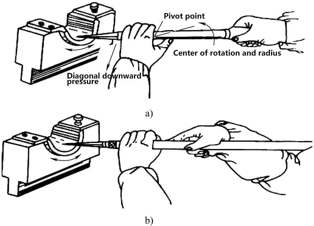
a) Curved surface scraping operation one
b) Curved surface scraping operation two
When scraping, align the front scraper edge with the high point, apply slant pressure along the inner arc tangent with the left hand, while the right hand holds the handle. Use the left hand as the pivot point for circular motion, guiding the scraper along the inner arc.
Therefore, from an action principle perspective, the front scraper edge has both a rotation motion controlled by the right hand (slight rotation around the scraper axis) and a swinging motion along the inner arc controlled by the left hand, resulting in a helical movement of the scraper front edge during scraping.
As shown in figure 25b, place the back part of the scraper blade and handle on the shoulder, and use both hands to grasp the blade for curved surface scraping, applying the same principles as above.
Similar to flat surface scraping, curved surface scraping also requires: gentle blade lowering, steady pressing, and quick blade lifting.
4. Analysis of scraping surface defects
Table 2 Scraping surface defect analysis
| Defect type | Causes of defects |
| Scraping pits | 1) Incorrect wedge angle of the scraper, too small wedge angle during fine or precision scraping; 2) Too large scraping clearance angle; 3) Excessive scraping pressure; 4) Scraping marks too long, lifting the scraper too slowly |
| Scraping chatter marks | 1) Too heavy drop of the scraper; 2) During planar scraping, the blade is not flat, that is, there is an angle between the blade and the scraping surface. During curved surface scraping, the angle of the curved scraper is incorrect; 3) The material distribution of the scraping surface is uneven |
| Scraping knife marks Thread-like marks appear | 1) There is a notch on the scraper; 2) Local high point material is too hard; 3) Hard objects adhere to the scraper blade; 4) Hard objects are trapped between the polishing tool and the polished workpiece, or there are burrs on the edge of the polishing tool |
5. Scraping safety requirements
- Before scraping, remove sharp edges and burrs from the workpiece; during scraping, pay special attention to the position and force of the knife near sharp corners to avoid arm injury due to inertia.
- When scraping large workpieces that need to be moved or matched, pay attention to the safety of lifting and placing.
- When scraping, adjust the relative position between the operator and the workpiece appropriately. If the height is insufficient, use a wooden board for support, but ensure the board is stable after adjustment to ensure the operator can apply scraping force safely and prevent falls.
- When scraping to the edge of the workpiece, control the pressure and thrust to prevent accidental forward thrust of both the person and the knife due to excessive force.
- Scrapers should be properly stored after use and should not be used as pry bars.

