Punch and Die Clearance: Secrets to Perfect Parts
What if a tiny gap could make or break your next manufacturing project? In the world of punch and die…
Ampere – The unit of measurement for the flow of electrons (the amount of electrons passing per second) in a circuit.
For a material of a specific thickness, as the cutting current increases, the cutting speed must correspondingly increase.
For a material of a specific thickness, if the cutting current is increased, slag formation will decrease.
For a material of a specific thickness, choosing a lower cutting current usually results in better cut surface quality and top edge quality.
Under normal conditions, the lifespan of consumables at lower currents exceeds that of higher currents, especially evident when using oxygen cutting.
All plasma cutting devices specify a maximum cutting thickness and maximum piercing thickness.
| HD3070 100 AMP | Mild steel | 1/2″ | 1/2″ |
| Stainless steel | 1/2″ | 1/2″ | |
| Aluminium | 1/2″ | 1/2″ | |
| HD4070 200 AMP | Mild steel | 3/4 “(fine), 1” (general) | 1″ |
| Stainless steel | 3/4 “General | 1″ | |
| Aluminium | 3/4 “General | 1″ | |
| MAX 200 200 AMP | Mild steel | 2″ | 1″ |
| Stainless steel | 2″ | 7/8″ | |
| Aluminium | 2″ | 7/8″ | |
| HT 2000 200 AMP | Mild steel | 2″ | 1″ |
| Stainless steel | 2″ | 7/8″ | |
| Aluminium | 2″ | 7/8″ | |
| HT4001 400 AMP | Mild steel (O2) | 11/4″ | 1″ |
| Mild steel (N2) | 3″ | 1″ | |
| Stainless steel | 3″ | 1″ | |
| Aluminium | 3″ | 1″ | |
| HT4400 400 AMP | Mild steel | 2″ | 1 1/4″ |
| Stainless steel | 2″ | 1″ | |
| Aluminium | 2″ | 1″ |
The purity of the gas used in plasma devices, as a fundamental usage condition, must meet the requirements listed in the table below. Otherwise, the cutting quality could decrease, the lifespan of consumable components could drastically reduce, and the plasma device might malfunction.
Supply Pressure
To ensure the proper operation of the plasma device, strict requirements are set for the inlet pressure/flow rate of the gas control box. It is strongly recommended to use a highly reliable pressure regulator, installed near the entrance of the gas control box.
Select a high-quality (2-stage) pressure regulator, and refer to the plasma arc cutting device manual for rated pressure and flow rate parameters.
Operators should frequently monitor to promptly understand whether the pressure and flow can meet the requirements.
Factors to Consider
Material type for cutting
Desired cutting quality
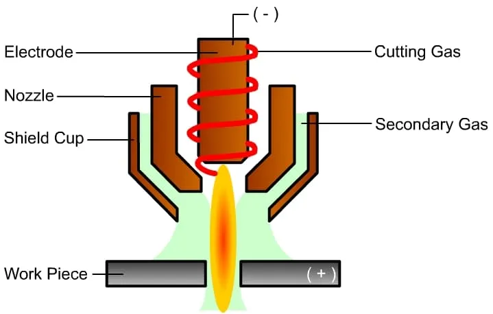
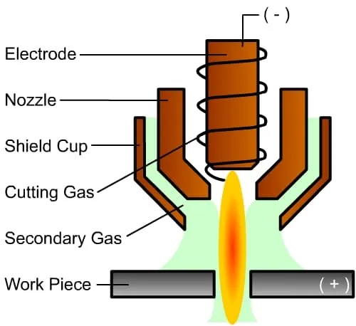
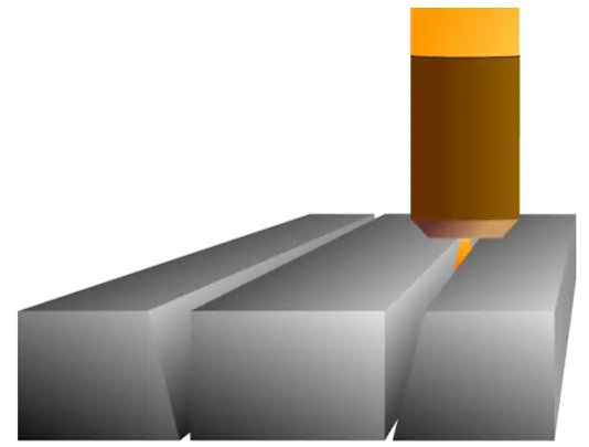
Plasma gas, used for material cutting, is also known as cutting gas. It is the ionized gas expelled from the nozzle.
Advantages
Disadvantages
Advantages:
Disadvantages:
Advantages:
Disadvantages:
Advantages:
Disadvantages:
Shielding gas is used to isolate the cutting area from the atmosphere, resulting in a cleaner cut surface. This gas also participates in the plasma cutting process. It surrounds the plasma arc and further compresses it towards the core, aiding in the cooling of the cutting nozzle.
By creating a microclimate around the cut surface, it isolates it from oxygen. The choice of shielding gas type depends on the plasma gas.
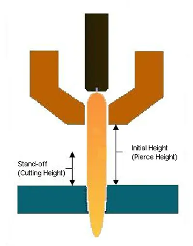
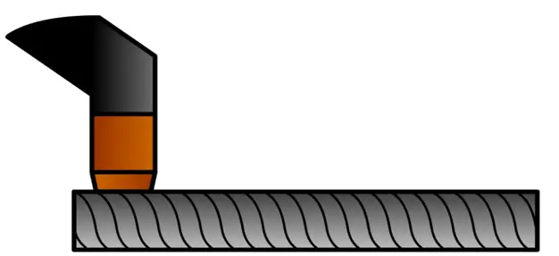
The piercing height refers to the initial distance from the torch to the surface of the material being cut during the piercing process.
The cutting height, on the other hand, is the distance that needs to be maintained from the torch to the surface of the material being cut during the cutting process.
The Height Control Monitor oversees the circuit voltage of the height controller, making appropriate adjustments as needed. The height of the cutting torch impacts the perpendicularity of the cutting surface and other aspects of cutting quality.
Arc voltage height control ensures the cutting torch maintains a consistent distance (height) from the workpiece, even on uneven plate materials.
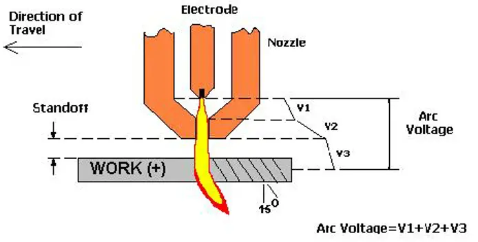
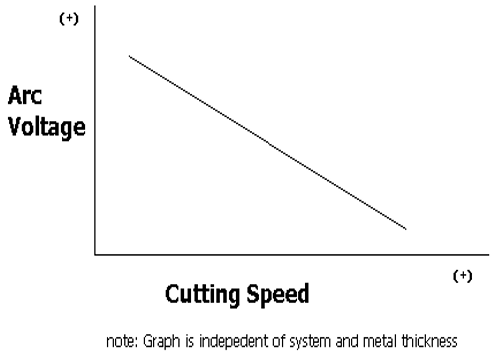
As the cutting speed increases, the arc voltage must be reduced, and vice versa.
Reasons for changes in cutting speed:
Torch reactions to changes in speed:
The cutting speed is appropriate.
The optimal cutting thickness corresponding to the cutting current should be selected from the middle section of the cutting parameter table.
The cutting speed is accurate; the arc lags slightly.
The cutting height is accurate; the voltage is dialed in.
Beyond oxy-fuel cutting of low carbon steel, the trailing edge shape of other materials’ cut surfaces does not effectively indicate the cutting speed.
It’s essential to consider the cut surface’s inclination angle, the degree of slag adhesion, and other appearance attributes, along with the surface’s smoothness or roughness, to accurately assess the cutting speed.
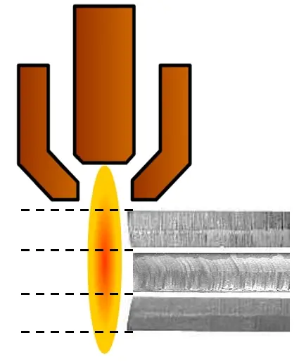
Concave cut surfaces may be due to excessively low cutting heights or overuse of consumables. Conversely, convex cut surfaces could indicate overly high cutting heights or excessive use of consumables.

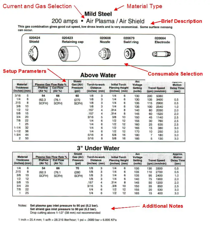
The cutting parameter table provides the essential parameters for cutting. The gas flow must be adjusted according to this table, unless special instructions dictate additional adjustments to enhance the cut quality.
It’s crucial to make slight alterations to parameters such as the cutting speed, torch height, and arc pressure to achieve optimal cutting results. Before starting the cut and after replacing consumables, it’s necessary to blow air for more than a minute.
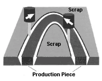
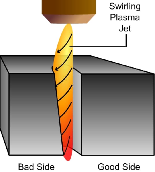
Clockwise: Cutting the outer edges of the workpiece.
Counterclockwise: Cutting the inner holes of the workpiece.
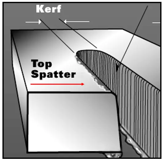
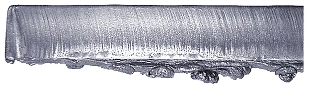
Dross is the material that is not entirely blown away from the kerf.
It manifests in three forms:
Spherical slag accumulation is substantial, allowing for large-scale removal that is easily achieved.
Cause:
Solution:
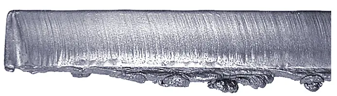
The slag accumulation appears in thin rolls and is difficult to remove.
Possible causes:
Solutions:
Top-side spatter, visible on both sides of the cut, typically occurs only in air plasma cutting. Gradually reduce the arc voltage (not exceeding 5V) until the top-side spatter disappears.
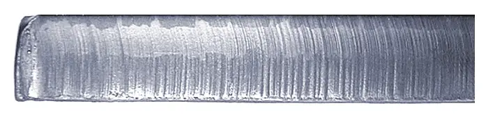
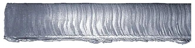
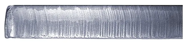
Trailing lines refer to the striations left on the cutting surface during the cutting process. The smoother the cutting surface, the smaller the current ripple output from the plasma source. The shape of these striations depends on the cutting method.
For instance, with appropriate speed, using nitrogen or argon-hydrogen for cutting results in striations that are slightly curved and inclined at approximately 15 degrees. In contrast, using oxygen for cutting produces almost vertical striations.
Employing the comparison of the trailing edge to determine the optimal cutting speed is an excellent choice.
A vertical trailing edge indicates the cutting speed is too slow.
An excessive trailing edge suggests that the cutting speed is too fast.
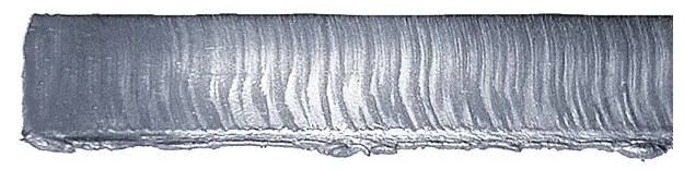
Generally, when the trailing edge is inclined at 10-15°, it signifies the cutting speed is appropriate.
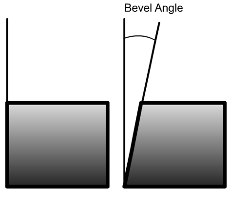
The cutting face tilt angle is the angle between the cutting face and the vertical line. If the cut is perfectly straight, then it should achieve a 0° angle.
The standard angle for a rectangular shape should be ≤4° on all four sides.
A higher cutting height equates to a positive cutting face tilt angle, while a lower cutting height relates to a negative cutting face tilt angle.
Excessive bevel on the cutting surface
The impact of torch height on the bevel angle in cutting processes.
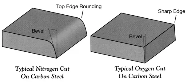
Compared to nitrogen cutting, the outcome of oxygen cutting presents distinct edges around the workpiece with minimal slag.
The workpieces obtained from oxygen plasma cutting are comparatively cleaner, with superior weldability, formability, and machinability on the cut surfaces.
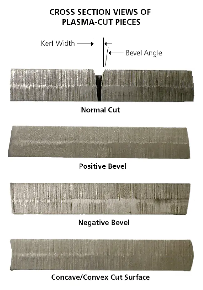
The kerf is the space (or the removed material) formed during the cutting process.
The kerf width is crucial for the dimensional accuracy of the workpiece.
Kerf Width = 1.5-2.0 x cutting nozzle diameter
Slower speed = wider kerf
Higher current = wider kerf
Rule: The diameter of the hole being cut must be at least twice the thickness of the material being cut. When cutting smaller holes, a conical hole may form.
