Step-by-Step Guide for Selecting the Right Face Milling Cutter
When it comes to optimizing your milling operations, selecting the right face milling cutter can make all the difference between…
Welding is an intricate craft that demands precision, knowledge, and the right parameters to achieve optimal results. Have you ever struggled with selecting the right welding current for different metal thicknesses, or wondered about the ideal electrode diameter for your project? These decisions are crucial, as they significantly impact weld penetration and overall quality. In this article, we’ll delve into the specifics of welding current, electrode diameter, and metal thickness, providing you with detailed guidelines and technical references to enhance your welding proficiency. By the end, you’ll be equipped with the knowledge to make informed choices, ensuring your welds are both strong and aesthetically pleasing. Ready to master the art of selecting the perfect welding parameters? Let’s dive in!
Welding current, measured in amperes (amps), is the flow of electrical charge through the welding circuit during the welding process. It is a critical parameter that influences the amount of heat generated at the welding arc, essential for melting the base and filler materials to facilitate their fusion. The correct selection of welding current directly affects weld penetration, bead shape, and overall weld quality.
Amperage, often used interchangeably with welding current, determines the rate at which electrons flow through the welding circuit. Higher amperage results in increased heat generation, enhancing weld penetration and deposition rates, while lower amperage is suitable for thin materials to avoid burn-through but may lead to inadequate penetration on thicker materials.
Welding current significantly impacts the depth of penetration and the extent of fusion between the base metals. Higher welding currents increase penetration, creating a stronger metallurgical bond and improving joint strength. However, excessive current can lead to burn-through, where the weld pool penetrates too deeply, potentially compromising the structural integrity of the weld.
Optimal welding current settings contribute to a smooth, aesthetically pleasing weld bead. In contrast, too high a current can cause defects such as excessive spatter, undercutting, and a rough bead appearance. In resistance spot welding of galvanized steel, higher currents can cause zinc-rich areas and increased spatter, reducing the visual and structural quality of the weld.
The heat generated by welding current affects the microstructure of the weld zone. Higher currents can result in a coarser grain structure, which might reduce mechanical properties such as tensile strength. Properly managing welding current is crucial for achieving a fine, uniform microstructure, which enhances the strength and durability of the weld.
Choosing the right welding current depends on the thickness of the base material. The following table provides a general guideline for welding current settings based on metal thickness for common welding processes:
| Metal Thickness (inches) | Welding Current (amps) |
|---|---|
| 0.125 | 50-100 |
| 0.250 | 100-200 |
| 0.375 | 200-300 |
| 0.500 | 250-350 |
| 0.750 | 300-400 |
These values serve as starting points and may require adjustments based on specific welding conditions, material properties, and desired weld characteristics. It is essential to conduct trial welds and fine-tune the current settings to achieve optimal results.
Understanding welding current and its effects on the welding process is fundamental for achieving high-quality welds. By selecting the appropriate current for the material thickness and welding conditions, welders can enhance weld penetration, minimize defects, and ensure the structural integrity of the welded joints.
Electrode diameter refers to the thickness of the welding electrode and is essential for ensuring a high-quality weld. Selecting the right electrode diameter is crucial for achieving a stable arc, reducing spatter, ensuring efficient deposition rates, and providing appropriate heat input for optimal penetration and weld strength.
Choosing the correct electrode diameter primarily depends on the thickness of the metal being welded. Here are some general guidelines:
For materials up to 1/8 inch (3.2 mm) thick:
For materials over 1/4 inch (6.35 mm) thick:
Electrode diameter directly influences the required welding current for optimal performance. Larger electrodes require higher currents to generate sufficient heat for melting and fusion, while smaller electrodes operate at lower currents to prevent overheating and burn-through. Here’s how electrode diameter affects these parameters:
The following table provides a guideline for selecting electrode diameter based on metal thickness:
| Metal Thickness | Electrode Diameter | Welding Current |
|---|---|---|
| Up to 1/8 | 1/16 – 3/32 | 40-90 |
| 1/8 to 1/4 | 3/32 – 1/8 | 70-130 |
| Over 1/4 | 1/8 – 5/32 | 100-200 |
These values serve as a starting point and may need adjustments based on specific welding conditions and material properties. Conducting trial welds and fine-tuning the parameters can help achieve the desired weld quality.
Metal thickness is a crucial factor in welding that influences the choice of welding parameters and techniques. It plays a significant role in determining the heat input, welding speed, and overall weld quality. Understanding how to adjust welding parameters based on metal thickness is essential for achieving strong and defect-free welds.
Amperage, or welding current, must be adjusted according to the thickness of the metal. The general rule of thumb is that each 0.001 inch of metal thickness requires approximately 1 amp of welding current; for example, welding a 0.125-inch thick metal typically requires around 125 amps. Thicker metals necessitate higher amperage to ensure sufficient heat for proper fusion, while lower amperage is essential for thin metals to avoid burn-through.
Voltage affects the arc length and, consequently, the bead shape. Higher voltage produces a longer arc, resulting in a wider and flatter bead, which is beneficial for thicker metals. Conversely, lower voltage results in a shorter arc and a narrower bead, which helps prevent excessive heat input on thin metals. Finding the optimal voltage is key to maintaining a stable arc and achieving desired weld profiles.
In MIG welding, the diameter of the welding wire and its feed speed should be chosen based on the metal thickness. Larger wire diameters are suitable for thicker metals, providing higher deposition rates and deeper penetration. The wire feed speed also influences the weld characteristics; higher speeds can increase deposition rates but may reduce penetration, necessitating careful balancing.
The type of shielding gas used in welding also varies with metal thickness. For example, pure argon is typically used for thin aluminum, while a mix of argon and CO2 is preferred for thicker steel. The choice of shielding gas impacts the arc stability, penetration, and overall weld quality.
Welding thin metals requires precise control over the welding parameters to avoid burn-through and distortion. Key practices include:
For thicker metals, ensuring adequate penetration and fusion is critical. Recommended practices include:
Adjusting welding parameters based on metal thickness is essential for achieving optimal welds. By following these best practices, welders can ensure strong, reliable joints with minimal defects.
MIG welding (Gas Metal Arc Welding) is popular for its efficiency and ease of use.
Advantages:
Limitations:
Settings:
TIG welding (Gas Tungsten Arc Welding) is renowned for its precision and high-quality welds.
Advantages:
Limitations:
Settings:
Stick welding (Shielded Metal Arc Welding) is versatile and widely used.
Advantages:
Limitations:
Settings:
Flux Cored Arc Welding (FCAW) offers versatility and efficiency, combining benefits of MIG and Stick welding.
Advantages:
Limitations:
Settings:
Selecting the correct welding parameters begins with understanding the material type, thickness, and joint design. Different materials and joint configurations require specific settings to achieve optimal weld quality. Refer to material data sheets and Welding Procedure Specifications (WPS) for guidelines.
Consider the welding position (flat, horizontal, vertical, or overhead) as it affects the weld pool’s behavior. Adjust parameters like amperage, voltage, and travel speed to accommodate the position and ensure a stable weld. Balance cost, efficiency, and quality by considering equipment costs, consumables, and the efficiency of the welding process.
Voltage and amperage influence weld penetration and quality. Proper settings ensure strong, defect-free welds.
Travel speed affects the weld bead’s shape and quality. Optimal travel speed is essential for consistent welds and avoiding issues like burn-through or lack of fusion.
In MIG and FCAW processes, wire feed speed is crucial for maintaining a consistent deposition rate and achieving the desired weld characteristics. Adjust wire feed speed to control the weld pool and penetration.
Recent studies indicate that Friction Stir Welding (FSW) can produce higher tensile strength compared to traditional MIG and TIG processes, impacting mechanical properties such as tensile strength, impact resistance, hardness, and microstructure of the weldments.
Choosing the right welding current and electrode size is essential for producing high-quality welds. Incorrect settings can lead to several common issues that compromise the weld’s integrity and appearance.
Burn-through occurs when the welding current is too high or the electrode diameter is too large for the material thickness, resulting in excessive heat input that causes the molten weld pool to penetrate completely through the base material, creating holes.
Solutions:
Inadequate penetration occurs when the welding current is too low or the electrode diameter is too small, preventing sufficient heat to fully fuse the base materials. This results in weak joints and poor weld strength.
Solutions:
Burn-through and inadequate penetration are two sides of the same coin and require careful balancing of welding parameters.
Welding dissimilar metal thicknesses presents unique challenges, including uneven heat distribution and different thermal expansion rates.
By understanding the common welding problems and their solutions, welders can enhance the quality and reliability of their welds. Proper parameter selection, equipment maintenance, and operator skill are key to overcoming these challenges and achieving successful welding outcomes.
Weld quality is influenced by several critical factors, each playing a significant role in determining the integrity, appearance, and performance of the weld. Understanding these factors helps in achieving optimal results in various welding applications.
Key welding parameters such as current, voltage, travel speed, and shielding gas composition have a direct impact on weld quality. These parameters must be carefully selected and controlled to ensure the desired weld characteristics.
The properties of the base and filler materials, such as their chemical composition, thickness, and thermal conductivity, significantly impact weld quality. Different materials, with their unique compositions and thicknesses, require tailored welding parameters to ensure proper fusion and penetration.
The skill and technique of the welder play a critical role in determining weld quality. Handling the welding equipment correctly, maintaining a consistent travel speed, and keeping the right arc length are crucial for producing high-quality welds.
Systematic experimentation and analysis are necessary to identify the optimal welding parameters for each application. Techniques such as the Taguchi method and analysis of variance (ANOVA) can help in understanding the effects of various parameters and their interactions.
Implementing real-time monitoring and control systems ensures consistency and early detection of deviations that could compromise weld quality.
Regular testing and inspection of welds are essential for validating weld quality and ensuring that parameters are within acceptable ranges.
Regularly reviewing and adjusting welding parameters based on test results and new materials or conditions helps maintain high standards of weld quality.
Using advanced technologies like machine learning and optimization algorithms can improve the predictability and efficiency of selecting welding parameters, resulting in superior weld quality.
By understanding and controlling the factors affecting weld quality, welders can achieve optimal penetration, minimize defects, and ensure the structural integrity of their welds. Regular monitoring, testing, and continuous improvement are key to maintaining high standards in welding applications.
Below are answers to some frequently asked questions:
To select the right welding current for different metal thicknesses, it’s essential to consider the specific requirements of the welding process and the characteristics of the metal being welded. The primary factor influencing welding current is the thickness of the metal; thicker metals require higher currents to achieve adequate penetration and strength, while thinner metals need lower currents to prevent overheating and burn-through.
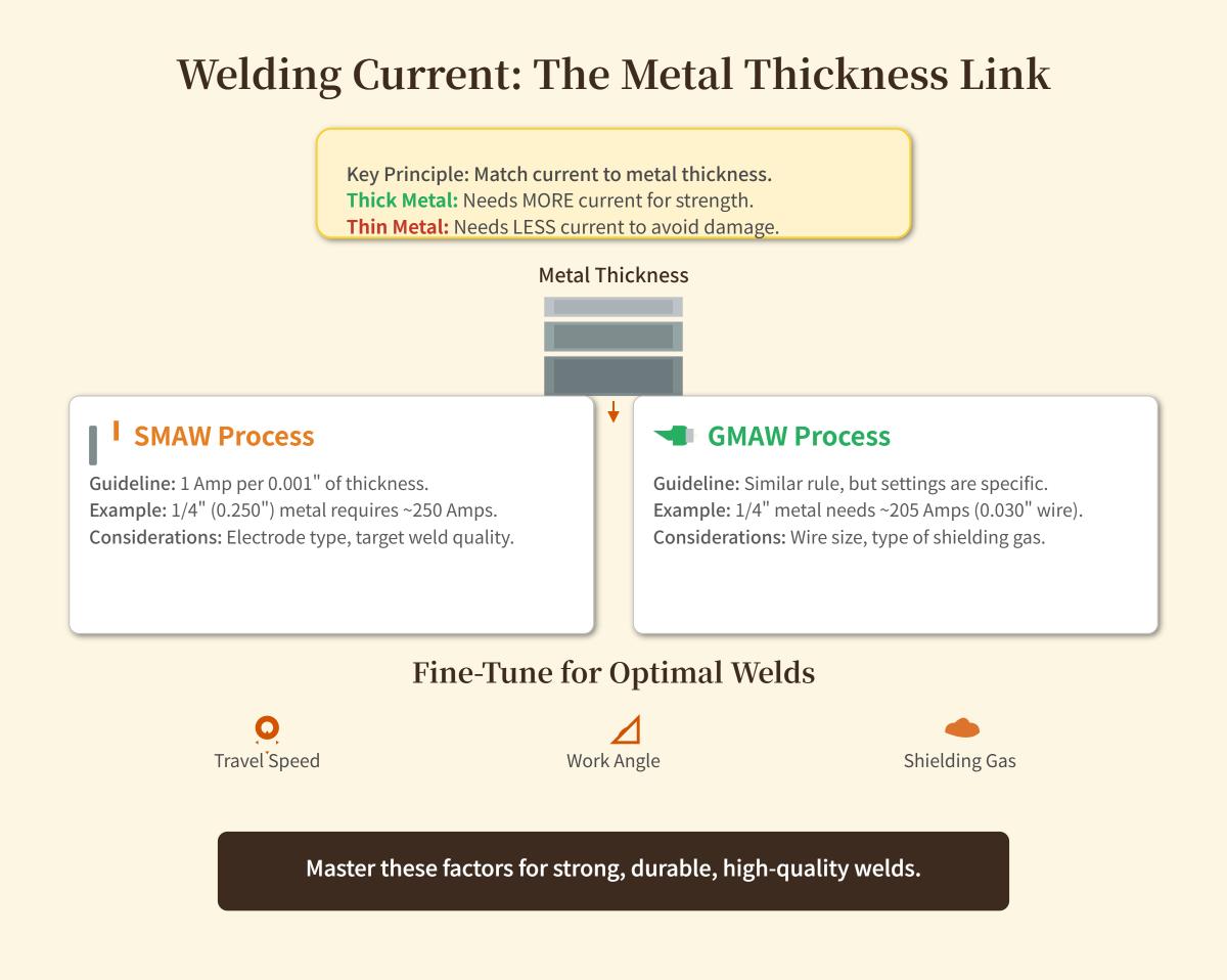
For Shielded Metal Arc Welding (SMAW), a common guideline is to use about 1 amp per 0.001 inches of metal thickness. For instance, welding a 1/4 inch (0.250 inches) thick metal would typically require approximately 250 amps. Adjustments may be necessary based on electrode type and desired weld quality.
In Gas Metal Arc Welding (GMAW), a similar rule of thumb applies, but adjustments for wire size and shielding gas can impact the settings. For example, welding 1/4 inch thick metal might require around 205 amps with a 0.030-inch wire size.
Fine-tuning the travel speed, work angle, and shielding gas can further optimize weld quality. By understanding these parameters and making necessary adjustments, welders can achieve optimal results and ensure strong, durable welds.
When selecting the right electrode diameter for welding, it is crucial to consider the thickness of the base metal. For thin metals up to 1/8 inch (approximately 3 mm) thick, use smaller diameter electrodes such as 1/16 inch (1.6 mm) or 3/32 inch (2.4 mm). These smaller electrodes provide a lower deposition rate and less heat, which helps prevent burn-through and ensures a clean weld. For thicker metals over 1/4 inch (approximately 6 mm), larger diameter electrodes like 5/32 inch (4 mm) or 1/4 inch (6.35 mm) are recommended. These larger electrodes increase the deposition rate and offer deeper penetration, which is necessary for efficiently welding thicker materials. Always consider the base metal thickness, welding position, material type, and welding process to achieve optimal results.
Electrode diameter significantly influences welding current and penetration. Larger electrode diameters require higher welding currents to maintain a stable arc and effectively melt the material. This is due to the increased cross-sectional area, which demands more current to generate sufficient heat. Conversely, smaller diameter electrodes operate at lower welding currents but have higher current density, leading to deeper penetration at the same current level.
Current density is a crucial factor in penetration: smaller electrodes concentrate the current into a smaller area, producing deeper penetration. For instance, when welding with two electrodes of different diameters at the same current, the smaller electrode achieves greater penetration. However, increasing the welding current for larger diameter electrodes can compensate for their lower current density, ensuring adequate penetration.
For optimal results, thinner materials benefit from smaller diameter electrodes with lower currents to avoid excessive heat and burn-through while achieving sufficient penetration. In contrast, thicker materials require larger diameter electrodes with higher currents to ensure full penetration and strong welds. Thus, selecting the right combination of electrode diameter and welding current is essential for achieving optimal weld quality.
Welding dissimilar metal thicknesses presents several challenges due to differences in thermal properties, mechanical strength, and chemical composition. Common problems include:
To mitigate these issues, it is essential to carefully control welding parameters, such as current, voltage, and speed. Preheating, using compatible filler materials, and applying post-weld heat treatments can also help improve weld quality.
Weld quality is influenced by several critical factors, including material, design, process, and service environment considerations. The chemical composition of both the base metal and welding materials is vital, as mismatched or improper selections can lead to defects like cracks and pores, compromising the weld’s integrity. Structural and joint design play a significant role by affecting stress distribution and heat flow, which can reduce defect formation and improve overall weld strength.
The choice of welding method (e.g., MIG, TIG, Stick) and specific welding parameters such as heat input, welding speed, and shielding gas composition are crucial. These parameters must be carefully controlled to prevent common issues like porosity and oxide contamination. Preheating and post-weld heat treatments help manage thermal stresses, enhancing the weld’s durability.
Environmental factors such as operating conditions, exposure to corrosive elements, and the use of protective gases to prevent contamination also significantly impact weld quality. Ensuring compatibility of materials, optimizing welding processes, and relying on skilled welders are best practices to achieve high-quality welds.
MIG, TIG, and Stick welding are distinct welding methods with unique characteristics suitable for different applications.
MIG Welding (Gas Metal Arc Welding) uses a consumable wire electrode fed from a spool and an external shielding gas, usually a mix of argon and CO₂. It’s known for its high speed, ease of learning, and ability to handle both thin and thick metals. MIG welding produces clean welds with minimal post-weld cleaning but is sensitive to wind, making it less ideal for outdoor use unless properly shielded.
TIG Welding (Gas Tungsten Arc Welding) employs a non-consumable tungsten electrode and an external shielding gas, typically argon. It excels in precision and control, making it perfect for thin materials, exotic metals, and critical welds. TIG welding delivers high-quality, precise welds but is slower and requires more skill than MIG welding.
Stick Welding (Shielded Metal Arc Welding) uses a consumable electrode coated in flux, which provides its own shielding atmosphere. It is versatile, portable, and effective on dirty, rusty, or painted metals, working well in outdoor and adverse conditions. While stick welding is slower and produces less aesthetically pleasing welds, it is highly reliable and cost-effective, particularly for repair work.
Each method has its own advantages and limitations, making the selection dependent on specific project requirements, environmental conditions, and the skill level of the operator.