I. Introduction to Planers
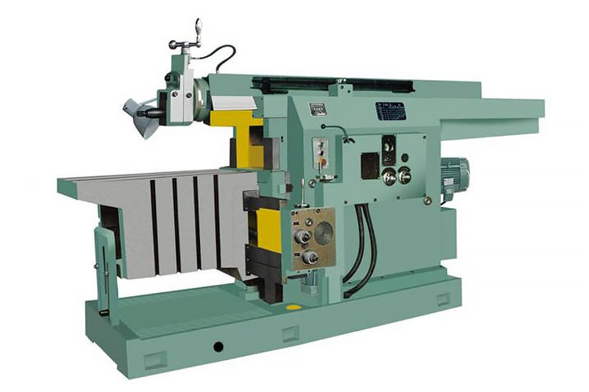
Planers mainly include bullhead planers and gantry planers, with bullhead planers being the most commonly used. The maximum planing length of a bullhead planer generally does not exceed 1000mm, suitable for processing medium and small parts. Due to its good rigidity and the ability of its tool holder to work simultaneously, the gantry planer is mainly used for processing large parts or multiple medium and small parts at the same time.
1. Composition of the Bullhead Planer
Figure 1 shows the appearance of the B6065 bullhead planer. In the model B6065, B stands for the category code of machine tools, indicating a planer, pronounced as “planer”; 6 and 0 respectively represent the group and series code of the machine tool, indicating a bullhead planer; 65 represents 1/10 of the maximum planing length, that is, the maximum planing length is 650mm.
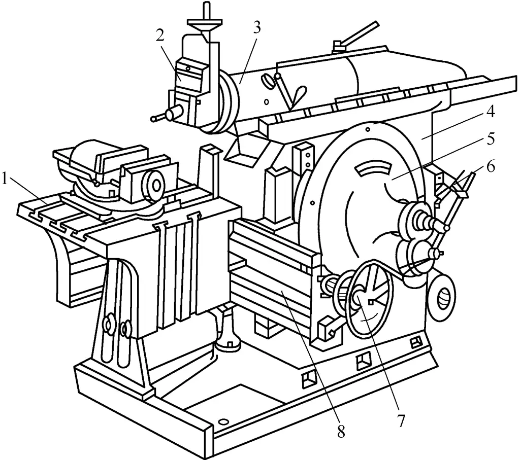
1—Worktable
2—Tool Holder
3—Slide
4—Bed
5—Swing Rod Mechanism
6—Speed Change Mechanism
7—Feed Mechanism
8—Crossbeam
(1) Bed
The bed is used to support and connect various parts of the planer. Its top surface horizontal guide rail allows the slide to drive the tool holder for reciprocating linear motion, and the vertical guide rail on the side allows the crossbeam to drive the worktable to lift. The bed interior has a main motion speed change mechanism and a swing rod mechanism.
(2) Slide
The slide is used to drive the tool holder to perform reciprocating linear motion along the horizontal guide rail of the bed. The speed, length, and position of the slide’s reciprocating linear motion can all be adjusted according to processing needs.
(3) Tool Holder
The tool holder is used to clamp the planer tool, its structure is shown in Figure 2. When turning the tool holder handle 5, the slide plate 4 moves the planer tool up and down along the guide rail on the scale disc 7, to adjust the back cutting amount or to make feed motion when processing a vertical surface.
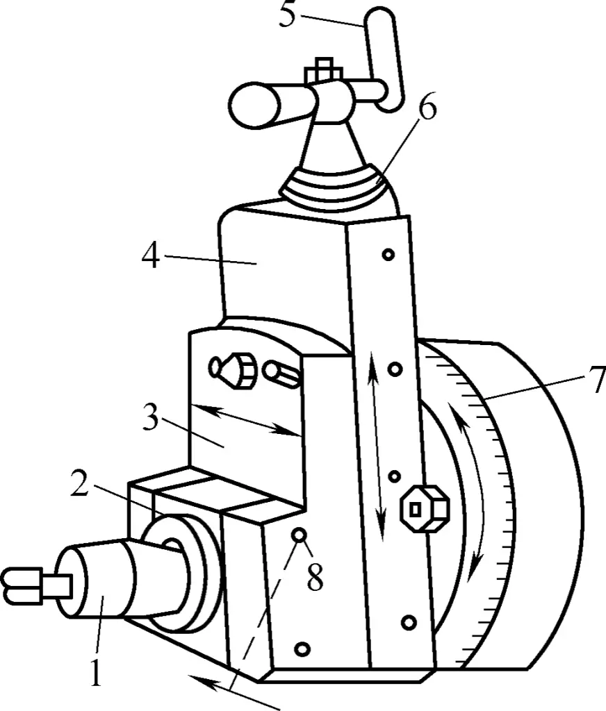
1—Knife Clamp
2—Lifting Blade Plate
3—Tool Post
4—Slide
5—Handle
6—Scale Ring
7—Scale Dial
8—Pin Shaft
Loosen the nut on the scale dial 7, turn the scale dial to a certain angle, which can make the tool holder feed diagonally to process an inclined surface. The tool post 3 is mounted on the slide 4. The lifting blade plate 2 can be lifted around the pin shaft on the tool post, so that the planer blade leaves the already machined surface of the part during the return stroke, reducing the friction between the tool and the part.
(4) Workbench
The workbench is used to install parts, which can be adjusted up and down along the beam, or moved horizontally along the beam guide or perform intermittent feeding motion.
2. The Transmission System of the Bullhead Planer
The transmission system of the B6065 type bullhead planer mainly includes a swing rod mechanism and a ratchet mechanism.
(1) Swing Rod Mechanism
Its function is to convert the rotational motion transmitted from the motor into the reciprocating linear motion of the slide block, with the structure shown in Figure 3. The upper end of the swing rod 7 is connected to the nut 2 inside the slide block, and the lower end is connected to the bracket 5. The eccentric slider 6 on the swing rod gear 3 is connected to the guide slot on the swing rod 7.
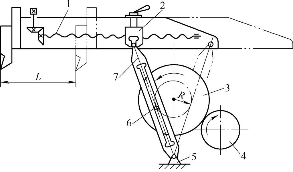
1—Screw
2—Nut
3—Swing Rod Gear
4—Small Gear
5—Bracket
6—Eccentric Slider
7—Swing Rod
When the swing rod gear 3 is rotated by the small gear 4, the eccentric slider moves up and down in the guide slot of the swing rod 7, thereby driving the swing rod 7 to swing left and right around the center of the bracket 5, so the slide block makes a reciprocating linear motion. With one rotation of the swing rod gear, the slide block drives the planer blade to reciprocate once.
(2) Ratchet Mechanism
Its function is to make the workbench perform an intermittent lateral feed at the moment before the slide block completes the return stroke and the planer blade cuts into the part again, with the lateral feed mechanism shown in Figure 4a, and the ratchet mechanism shown in Figure 4b.
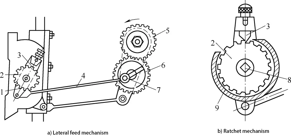
1—Pawl Bracket
2—Ratchet
3—Claw
4—Connecting Rod
5, 6—Gears
7—Eccentric Pin
8—Transverse Screw
9—Ratchet Cover
Gear 5 and the swing gear are integrated. When the swing gear rotates counterclockwise, gear 5 drives gear 6 to rotate, causing the connecting rod 4 to drive the claw 3 to swing counterclockwise. When the claw 3 swings counterclockwise, its vertical surface moves several teeth of the ratchet 2, causing the screw 8 to turn a corresponding angle, thereby achieving the transverse feed of the worktable.
However, when the ratchet swings clockwise, since the back of the claw is a sloped surface, it can only slide over the top of the ratchet teeth without moving the ratchet, so the worktable remains stationary. This achieves the intermittent transverse feed of the worktable.
3. Adjustment of the Shaper
(1) Adjustment of the stroke length, starting position, and speed of the slide
During planing, the length of the slide stroke should generally be 30~40mm longer than the length of the part being planed. The method to adjust the length of the slide stroke is by changing the eccentric distance of the eccentric block on the swing gear. The larger the eccentric distance, the larger the angle of swing of the swing rod, and the longer the stroke length of the slide; conversely, it is shorter.
Loosen the locking handle inside the slide, rotate the screw to change the starting point of the slide stroke, and move the slide to the required position. When adjusting the speed of the slide, it must be done after the machine is stopped; otherwise, the gears will be damaged. The speed of the shaper can be changed by changing the position of the variable speed gears through the transmission mechanism 6 (Figure 1).
(2) Adjustment of the size and direction of the worktable’s transverse feed
The feed motion of the worktable must meet the requirements of intermittent motion and coordinate with the working stroke of the slide, that is, at the end of the return stroke of the planer, the worktable moves transversely together with the workpiece by one feed amount. The feed motion of the shaper is achieved by the ratchet mechanism.
As shown in Figure 4, the claw frame 1 is loosely fitted on the crossbeam screw shaft, and the ratchet is connected to the screw shaft with a key. The size of the worktable’s transverse feed can be adjusted by changing the position of the ratchet cover, thereby changing the effective number of teeth the claw moves over the ratchet each time. When the claw moves over more teeth of the ratchet, the feed amount is large; otherwise, it is small.
In addition, it can also be adjusted by changing the eccentric distance of the eccentric pin 7. A smaller eccentric distance means a smaller swing angle of the claw frame, fewer ratchet teeth moved over by the claw, and a smaller feed amount; conversely, the feed amount is larger. If the claw is lifted and rotated 180°, the worktable can feed in the opposite direction. When the claw is lifted and rotated 90°, the ratchet is disengaged from the claw, allowing for manual feeding at this time.
II. Planer Tool
1. Types and Applications of Planer Tools
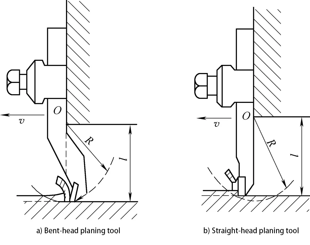
The geometric shape of the planer tool is similar to that of a lathe tool, but the cross-sectional area of the tool shank is 1.25~1.5 times that of a lathe tool to withstand greater impact forces. The front angle of the planer tool is slightly smaller than that of a lathe tool, and a larger negative rake angle is used to increase the strength of the tool head. A notable feature of the planer tool is that the tool head is often made bent.
Figure 5 shows a comparison between a bent-head planer tool and a straight-head planer tool. The purpose of making a bent head is to allow the tool head to bounce back and upwards around point O when the tool encounters a hard spot on the surface of the workpiece, causing the cutting edge to leave the surface of the workpiece, preventing it from biting into the already machined surface or damaging the cutting edge. Therefore, bent-head planer tools are more widely used than straight-head planer tools.
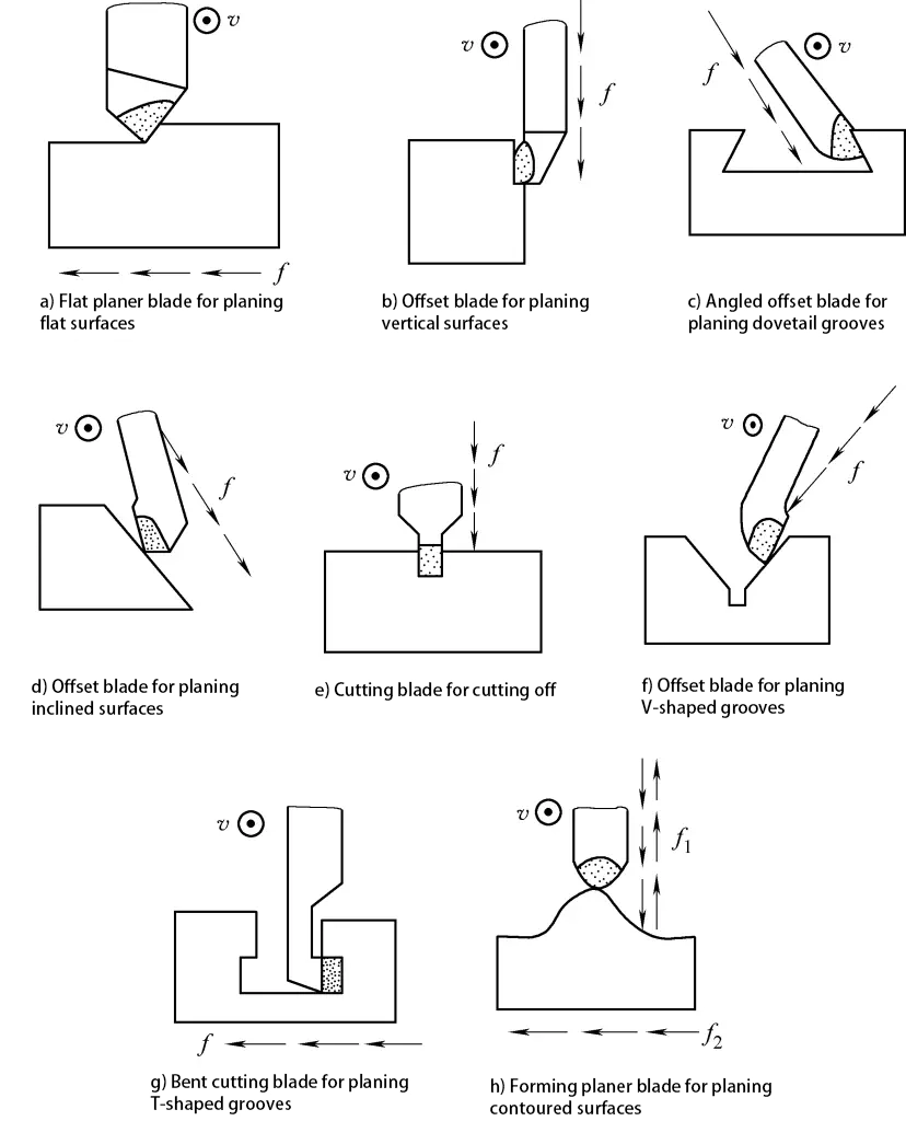
The shape and type of planer tools vary according to the shape of the surface being machined. Flat planer tools are used for machining horizontal surfaces; side tools for vertical surfaces, step surfaces, and inclined surfaces; angle side tools for angles and dovetail grooves; cutting tools for cutting or grooving; internal hole tools for machining internal surface (such as internal keyways); bent cutting tools for machining T-slots and side grooves; forming tools for machining formed surfaces.
2. Installation of Planer Tools
As shown in Figure 6, when installing the planer tool, align the turntable with the zero line to accurately control the back cutting amount. The tool head should not protrude too long to avoid vibration and breakage. The protruding length of a straight-head planer tool is generally 1.5~2 times the thickness of the tool shank, and the protruding length of a bent-head planer tool can be slightly longer, as long as the bent part does not touch the tool holder.
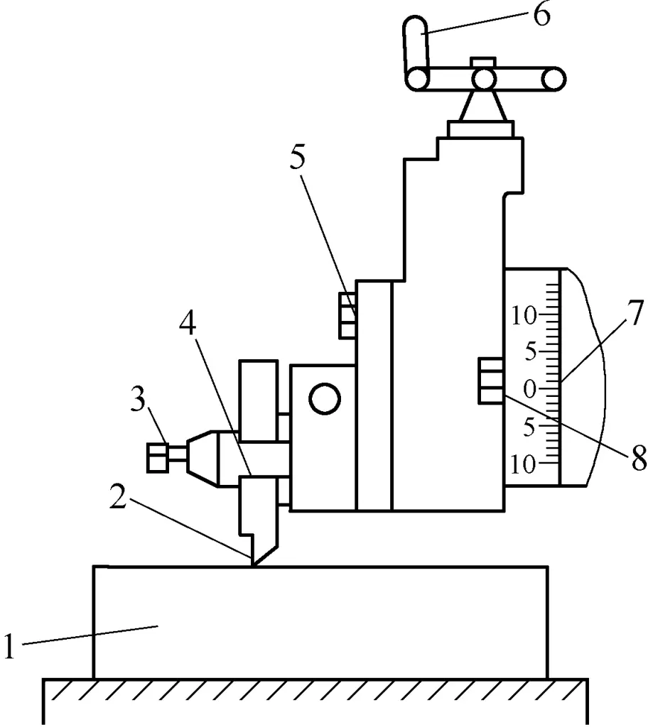
1—Workpiece
2—Tool head should protrude shortly
3—Tool clamp screw
4—Tool clamp
5—Tool holder screw
6—Tool post feed handle
7—Align the turntable with the zero line
8—Turntable screw
When installing or removing the tool, the tool tip should be kept away from the surface of the workpiece to prevent damage to the tool or scratching the surface of the workpiece. One hand must hold the planer blade while the other hand uses a wrench, applying force from top to bottom, otherwise, it is easy to lift the blade lifting plate, causing injury or pinching fingers.
III. Planing Process Technology
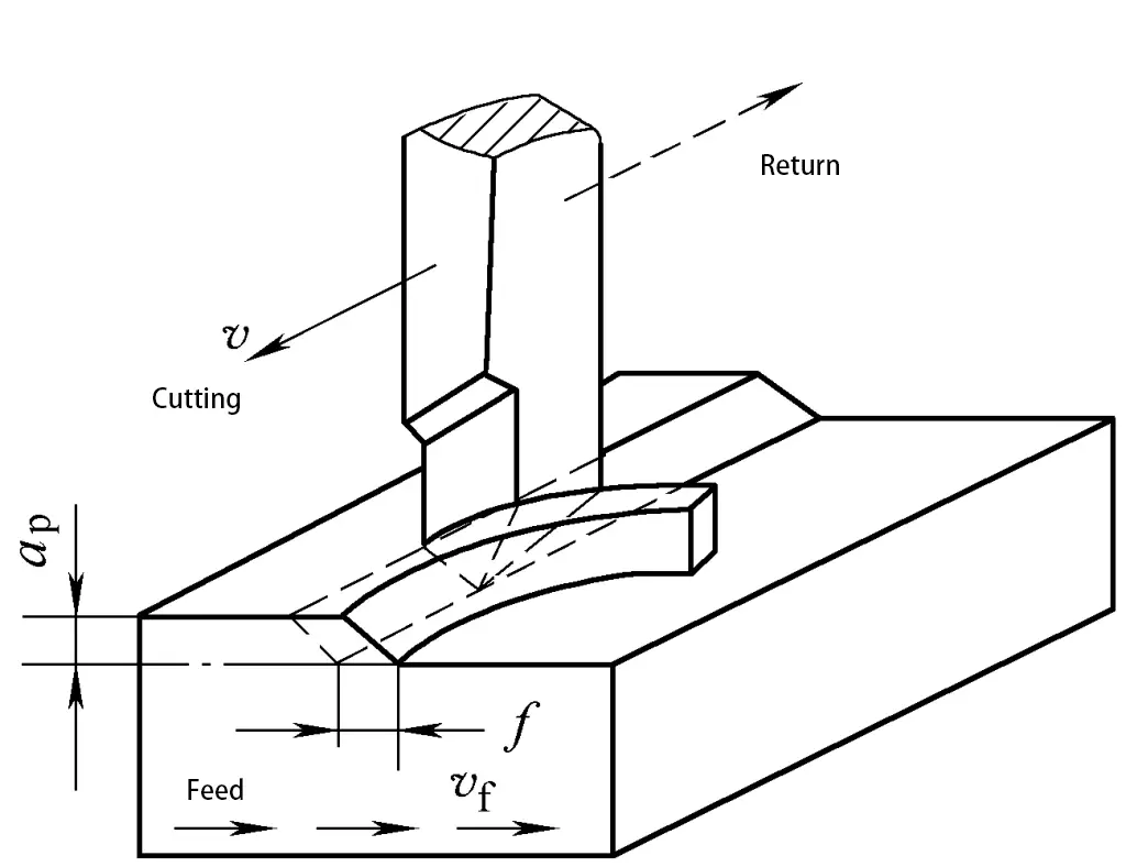
When machining on a shaper, the longitudinal reciprocating linear motion of the planer blade is the main motion, and the workpiece moves laterally intermittently with the worktable, as shown in Figure 7.
1. Characteristics of planing
(1) Generally lower productivity
Planing is a discontinuous cutting process, with sudden changes in cutting force when the tool enters and exits, causing impact and vibration, limiting the increase in planing speed.
Moreover, the actual cutting length of a single-edged planer blade is limited, and a surface often requires multiple strokes to be machined, with no work being done during the return stroke of the planer blade. For these reasons, the productivity of planing is generally lower than that of milling, but for the machining of narrow and long surfaces (such as guide surfaces) and multi-tool, multi-piece machining on gantry planers, its productivity may be higher than milling.
(2) Good versatility and adaptability of planing
The structure of the planer is simpler than that of lathes and milling machines, making adjustment and operation convenient; the shape of the planer blade is simple, similar to that of a lathe tool, and manufacturing, sharpening, and installation are all more convenient; generally, no cutting fluid is needed during planing.
2. Scope of planing
The dimensional tolerance grade of planing is generally IT9~IT8, and the surface roughness Ra value is 6.3~1.6μm. When using a wide blade for fine planing, the Ra value can reach 1.6μm. In addition, planing can also ensure a certain positional accuracy, such as the parallelism and perpendicularity between faces.
Planing is widely used in single-piece, small batch production, and repair work. Planing is mainly used for machining various planes (horizontal, vertical, and inclined surfaces), various grooves (straight grooves, T-slots, dovetail slots, etc.), and forming surfaces, as shown in Figure 8.
3. Basic operations of planing
(1) Installation of the workpiece
The method of installing the workpiece on the planer depends on the shape and size of the workpiece. Common methods include vise installation, worktable installation, and special fixture installation, similar to milling.
(2) Planing horizontal surfaces
- Correctly install the tool and workpiece.
- Adjust the height of the worktable so that the tool tip slightly touches the surface of the workpiece.
- Adjust the stroke length and starting position of the slide.
- Based on the material, shape, size, and other requirements of the part, reasonably select the cutting parameters.
- Trial cut, first manually trial cut. After feeding 1~1.5mm, stop the machine, measure the dimensions, adjust the back cutting amount based on the results, then automatically feed to continue planing. When the surface roughness Ra value of the part is required to be lower than 6.3μm, rough planing should be done first, followed by fine planing. During fine planing, the back cutting amount and feed rate should be smaller, and the cutting speed should be appropriately higher. In addition, during the return stroke of the planer blade, lift the blade lifting plate on the tool holder by hand to keep the tool away from the machined surface to ensure the quality of the part surface.
- Inspection. After the part is finished planing, stop the machine for inspection, and the part can be removed after the dimensions and machining accuracy are qualified.
(3) Planing vertical and inclined surfaces
1) The method of planing vertical surfaces is shown in Figure 9. In this case, an offset tool is used, and the protruding length of the tool is greater than the height of the entire planing surface. The tool post turntable should be aligned with the zero line to move the planer blade vertically.
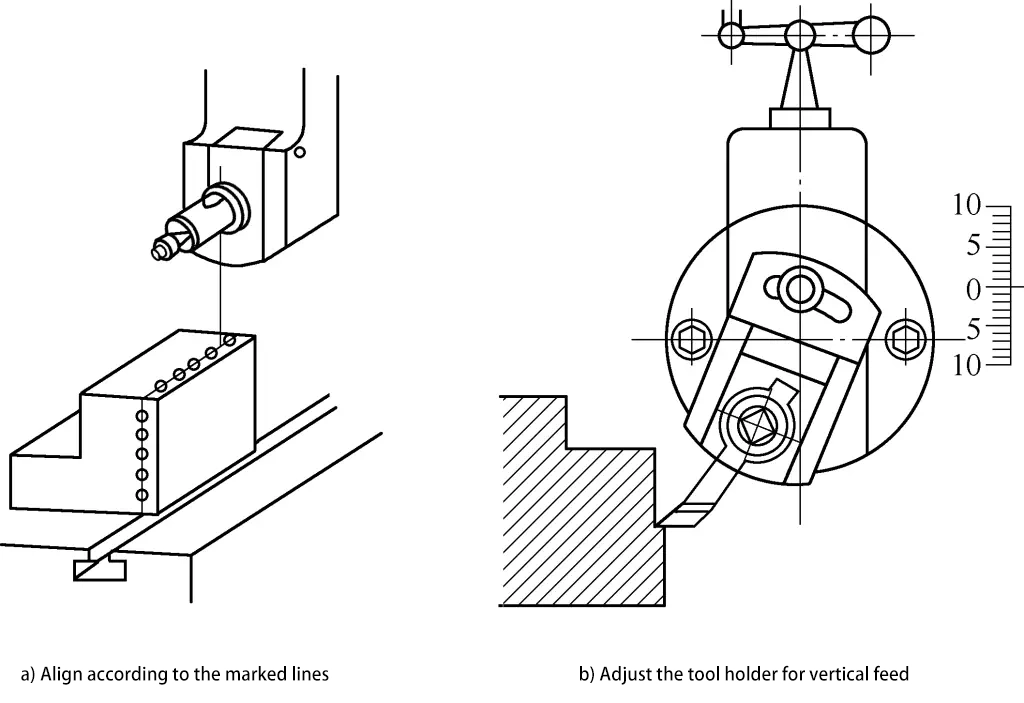
The tool holder must be deflected by 10° to 15° to lift the planer blade off the surface of the workpiece during the return stroke, reducing tool wear and avoiding scratches on the already machined surface. The method of machining vertical and inclined surfaces is generally used only when it is not possible or inconvenient to plane horizontal surfaces.
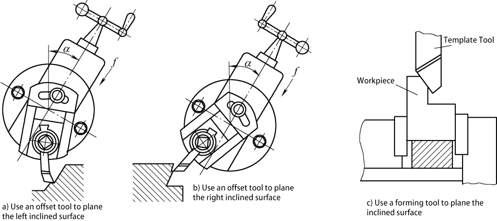
2) Planing an inclined surface is basically the same as planing a vertical surface, except that the tool post turret must be turned to a certain angle according to the inclined surface required by the part, so that the planer blade moves along the direction of the inclined surface. As shown in Figure 10, planing an inclined surface uses an offset blade or a template-formed planer blade, rotating the tool post handle for feed, which can plane the left or right inclined surface.
(4) Planing grooves
1) Planing straight grooves is done with a cutting tool by vertical feeding, as shown in Figure 11.

2) The method of planing V-shaped grooves is shown in Figure 12. First, roughly plane out the general shape of the V-shaped groove using the method of planing a flat surface, as shown in Figure 12a; then use a cutting tool to plane the right-angle groove at the bottom of the V-shaped groove, as shown in Figure 12b; next, plane the two inclined surfaces of the V-shaped groove using the method of planing an inclined surface with an offset blade, as shown in Figure 12c; finally, use a forming planer blade to finely plane to the dimensional accuracy and surface roughness required by the drawing, as shown in Figure 12d.

3) When planing T-shaped grooves, machining lines should first be drawn on the end face and upper surface of the workpiece, as shown in Figure 13.

4) Planing dovetail grooves is similar to planing T-shaped grooves, with machining lines first drawn on the end face and upper surface of the workpiece, as shown in Figure 14. However, when planing the side surfaces, an angled offset blade is required, as shown in Figure 10, and the tool post turret must be turned to a certain angle. The steps for planing dovetail grooves are shown in Figure 15.


5) Planing formed surfaces. When planing formed surfaces on a planer, it is common to first mark lines on the side of the workpiece, then move the planer blade for vertical feed and move the worktable for horizontal feed according to the lines, thus machining the formed surface, as shown in Figure 8h. Formed planer blades can also be used for machining, making the edge of the planer blade conform to the surface of the workpiece, forming in one go.

