Hardox vs. Domex: Key Differences and Best Uses
In the realm of high-performance steels, few names stand out as prominently as Hardox and Domex. Whether you’re a seasoned…
Planing processing is a method of cutting on a planer using the linear reciprocating motion of the planing tool (or workpiece) as the main motion. The feed motion is the intermittent movement of the workpiece or tool along a direction perpendicular to the main motion. Planing is a single-direction cutting process, that is, the cutting stroke, and during the return stroke, cutting is not performed, which is an idle stroke. To avoid damaging the already machined surface of the workpiece and to reduce tool wear, the planing tool needs to be lifted to clear the cut during the return stroke.
Since the main motion has to overcome the inertia of the moving parts when changing direction, this limits the increase of cutting speed and idle stroke speed. Additionally, due to the loss during the machine’s idle stroke, the productivity of planing processing is generally low in most cases. However, because the structure of planing machines and tools is simple, and they are easy to manufacture, install, and adjust, they are economically applied in single-piece and small-batch production.
Planing processing is mainly used for machining planes, parallel surfaces, vertical surfaces, steps, grooves, inclined surfaces, curved surfaces, and formed surfaces, etc., as shown in Figure 1. The machining accuracy of planing can reach IT9~IT8, and the surface roughness can reach Ra6.3~1.6μm, mainly used for roughing and semi-finishing.
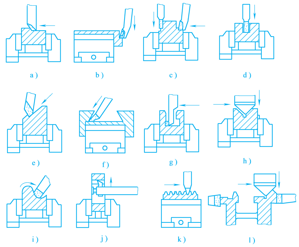
a) Planing flat surfaces
b) Planing vertical surfaces
c) Planing step surfaces
d) Planing right-angle grooves
e) Planing inclined surfaces
f) Planing dovetail-shaped workpieces
g) Planing T-slots
h) Planing V-grooves
i) Planing curved surfaces
j) Planing internal keyways in holes
k) Planing racks
l) Planing composite surfaces
Since planing processing can ensure a certain positional accuracy, it is very suitable for machining planes such as boxes and guide rails. Especially on high-precision and rigid gantry planers, using wide-blade planing tools for fine planing instead of scraping greatly improves machining accuracy and productivity. In addition, when machining narrow long planes or multiple workpieces simultaneously on a planer, its productivity is not lower than that of milling.
The main types of planer-type machine tools are the bullhead planer, gantry planer, and slotting machine.
The bullhead planer is suitable for planing planes, grooves, or shaped surfaces of medium and small workpieces with a length not exceeding 1000mm. Its appearance is shown in Figure 2. The main motion of the bullhead planer is the reciprocating linear motion of the sliding block 3 equipped with the tool in the horizontal guide rail on top of the bed 4. The tool post 1 can move up and down along the guide rail of the tool post base 2 to adjust the cutting depth, and it can also make a feed motion when machining vertical and inclined surfaces.
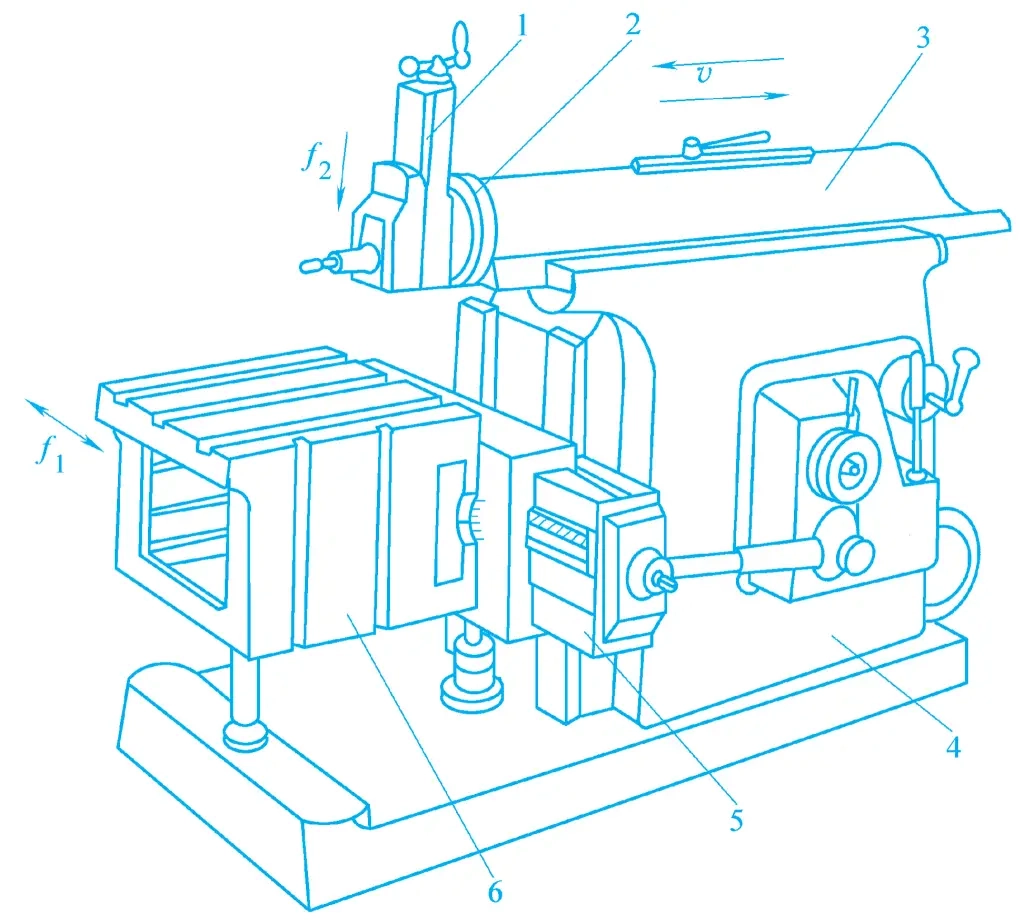
1—Tool post
2—Tool post base
3—Sliding block
4—Bed
5—Crossbeam
6—Worktable
According to machining needs, the tool post base 2 can be adjusted to allow the tool post to rotate left and right by 60° to facilitate the machining of inclined surfaces or grooves. During the machining process, the worktable 6 drives the workpiece to perform intermittent lateral feed motion along the crossbeam 5. The crossbeam 5 can move up and down along the vertical guide rail of the bed 4 to adjust the relative position between the workpiece and the planing tool.
The gantry planer is mainly used for processing various planes, grooves, and various guide surfaces on large or heavy workpieces, or for clamping several medium and small workpieces on the worktable for multi-piece processing. It can also use multiple planing tools for simultaneous planing, thereby greatly improving productivity.
Large gantry planers are often equipped with components such as milling heads and grinding heads, so that more processing content can be completed in one clamping. Compared with ordinary bullhead planers, gantry planers are larger in size, more complex in structure, have better rigidity, longer strokes, and higher machining accuracy.
Figure 3 is an external view of the gantry planer. The workpiece is clamped on the worktable 9, and the main motion is the reciprocating linear motion of the worktable along the horizontal guide rail of the bed. The two sides of the bed 10 are fixed with left and right columns 3 and 7, and the top ends of the two columns are connected with a top beam 4, forming a gantry frame with relatively good structural rigidity. The crossbeam 2 is equipped with two vertical tool posts 5 and 6, which can make horizontal feed motion along the crossbeam guide rail.
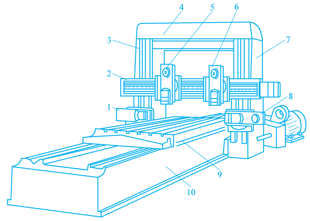
1, 8—Left and right side tool posts
2—Crossbeam
3, 7—Columns
4—Top beam
5, 6—Vertical tool posts
9—Worktable
10—Bed
The crossbeam 2 can be moved to a certain position along the guide rail of the column to adjust the relative position of the workpiece and the tool. The left and right side tool posts 1 and 8 are mounted on the left and right columns, respectively, and can perform vertical feed motion along the column guide rail to machine the side surfaces. To avoid damaging the workpiece surface with the tool during the idle stroke, the gantry planer is equipped with an automatic tool retraction device for the return stroke.
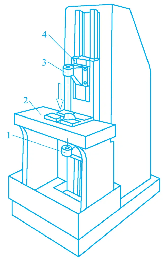
The external shape of the slotting machine is shown in Figure 4. The slotting machine is essentially a vertical bullhead planer, and its main motion is the reciprocating up and down linear motion of the sliding block driving the slotting tool. The sliding block guide rail base 3 can adjust the angle within a small range around the pivot axis 4 to machine inclined internal and external surfaces.
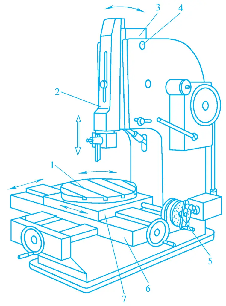
1—Round worktable
2—Sliding block
3—Sliding block guide rail base
The cross saddle 6 and the slide board 7 can respectively drive the workpiece to achieve lateral and longitudinal feed movements, and the round worktable 1 can rotate around the plumb axis to realize circular feed movement or indexing movement. The intermittent feed movement of the round worktable 1 in each direction is carried out in a short time after the end of the slide’s idle stroke. The indexing movement of the round worktable 1 is realized by the indexing device 5.
The machining range of the shaping machine is quite broad, and the machining cost is relatively low, but its productivity is not high, and it requires a high level of skill from the operator. Therefore, shaping machines are generally suitable for the processing of internal surfaces of workpieces in single-piece and small-batch production, such as square holes, polygonal holes, or internal keyways, etc.
Planer tools can be classified according to the shape of the surface being machined and the purpose of the tool, or according to the shape and structure of the tool itself. Classified by the shape of the machining surface and purpose, planer tools can generally be divided into flat planer tools, side planer tools, angle planer tools, cutting planer tools, bent cutting planer tools, and template planer tools, etc., as shown in Figure 5.
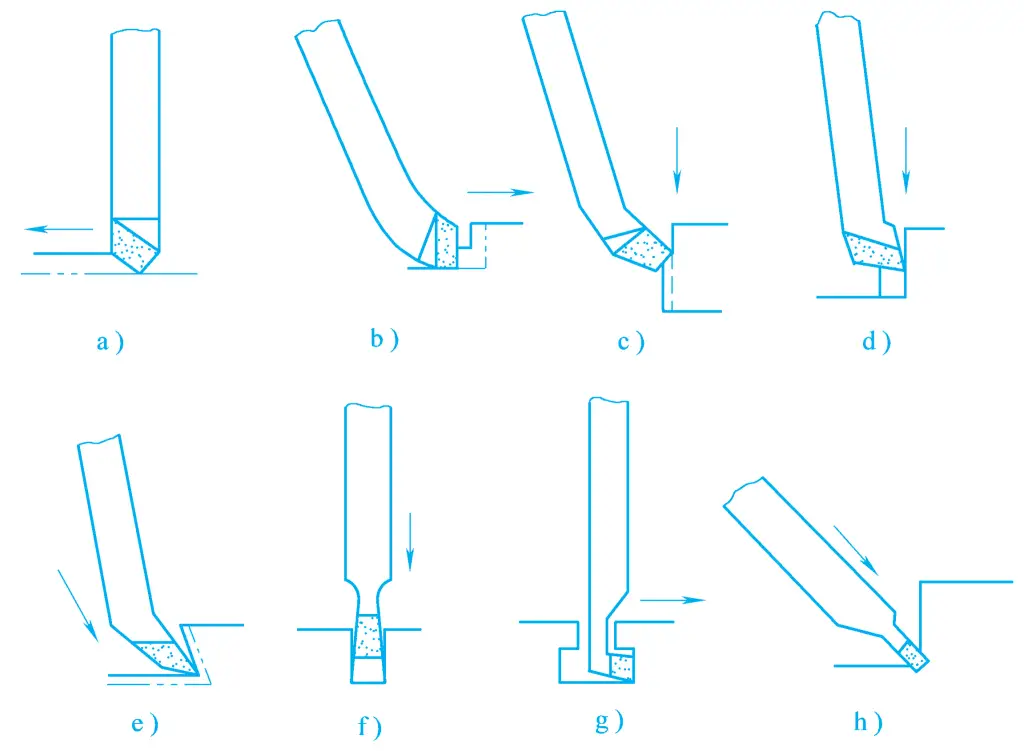
a) Flat Planer Tool
b), d) Step Side Planer Tool
c) Common Side Planer Tool
e) Angle Planer Tool
f) Cutting Planer Tool
g) Bent Cutting Planer Tool
h) Grooving Planer Tool
Among them, the flat planer tool is used for planing horizontal surfaces, the side planer tool is used for planing vertical surfaces, step surfaces, and outer inclined surfaces, etc., the angle planer tool is used for planing dovetail grooves and inner inclined surfaces, etc., the cutting planer tool is used for cutting off, grooving, and planing vertical surfaces, etc., the bent cutting planer tool is used for planing T-slots, and the template planer tool is used for planing V-slots and surfaces of special shapes, etc.
According to the shape and structure of the tool, planer tools can generally be divided into left-hand planer tools and right-hand planer tools, straight-head planer tools and bent-head planer tools, integral planer tools and assembled planer tools, etc.
When a bent-head planer tool encounters a large cutting resistance, the tool shank will deform and bend backward, causing the tool tip to spring up and backward, rather than digging into the workpiece like a straight-head planer tool. Therefore, to avoid damaging the workpiece surface and the tool, bent-head planer tools are generally more commonly used in actual production, as shown in Figure 6.
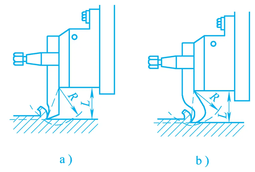
a) Straight-Head Planer Tool
b) Bent-Head Planer Tool
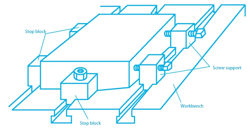
When planing flat surfaces on a shaper, the clamping method should be chosen according to the shape and size of the workpiece. Small-sized workpieces are generally clamped with a vise; when the workpiece is large, it can be clamped on the worktable with screw jacks and stops, as shown in Figure 7; the workpiece can also be clamped by using the boss or holes on the workpiece with bolted clamps, as shown in Figure 8.
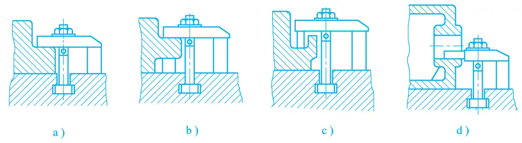
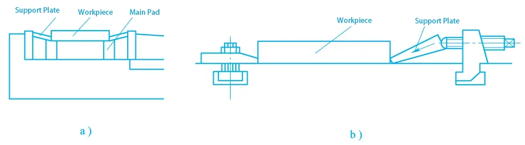
For thinner workpieces, clamping with a support plate is usually adopted, as shown in Figure 9. The support plate has an inclined surface near one side of the workpiece, with a small thickness that does not hinder the planing of the entire flat surface of the thin plate, and also makes the clamping force slightly inclined downwards, providing not only a horizontal clamping component but also a small vertical downward clamping force, which is beneficial for clamping the thin plate.
a) Clamped in a Flat-Nose Vise
b) Clamped on the Worktable
After the workpiece is correctly clamped, start the machine to move the ram so that the planer tool approaches the workpiece, then move the worktable laterally to position the workpiece under the planer tool, then rotate the tool post slide to make the tool tip touch the workpiece surface, then turn the worktable’s lateral handle to retract the workpiece from the tool tip, and rotate the tool post slide according to the selected back-cutting amount to feed the planer tool downward by one back-cutting amount.
Then start the machine, the worktable performs lateral feed, planing 1-1.5mm off the workpiece, and stop to measure. If the dimensions are not correct, retract the workpiece, adjust the back-cutting amount, then start the machine again, and the worktable performs lateral manual or automatic feed to plane off the excess metal of the workpiece.
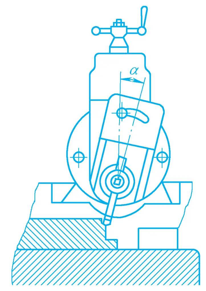
When planing a vertical surface on a bullhead planer, it is generally done by using an offset tool and manually feeding vertically. The adjustment of the back-cutting amount is achieved by moving the worktable laterally.
When installing the tool, first align the tool post with the zero line, and deflect the clapper box seat at a certain angle (0° to 15°) so that the upper end of the clapper box seat is deflected away from the direction of the workpiece surface. The purpose is to lift the planer blade off the workpiece surface during the return stroke to reduce tool wear and ensure that the machined surface of the workpiece is not damaged, as shown in Figure 10. If the height of the vertical surface is below 10mm, the clapper box seat can be set without deflection.
The method of planing step surfaces is a combination of planing horizontal surfaces and planing vertical surfaces. Figure 11 shows the feed method for precision planing of step surfaces with an offset tool. In addition, a cutting tool can also be used for precision planing.
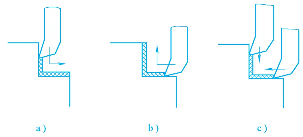
a) Continuous planing of vertical surface—horizontal surface
b) Continuous planing of horizontal surface—vertical surface
c) Separate planing of vertical surface and horizontal surface
When planing T-slots, four planer blades are used, namely a slotting cutter for planing straight slots, two curved cutters for left and right, and a 90° forming chamfer cutter. The planing steps are shown in Figure 12.
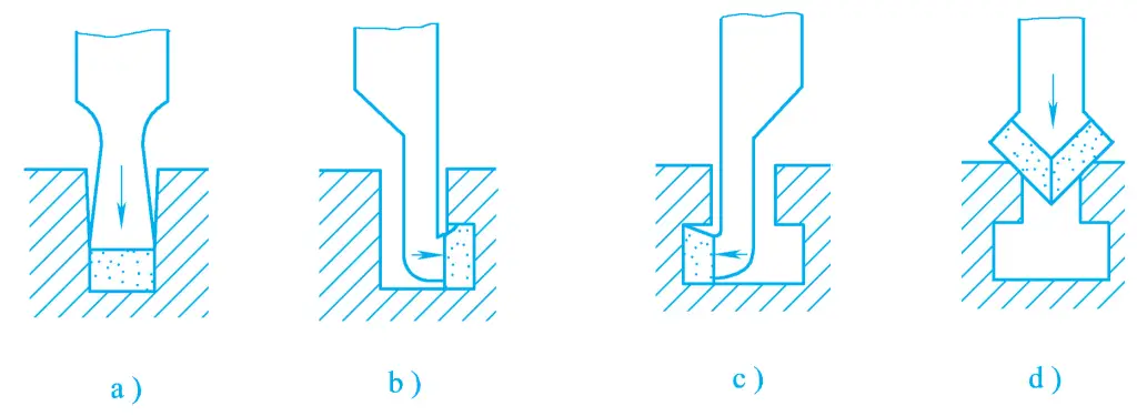
a) Slotting
b) Planing one side of the groove
c) Planing the other side of the groove
d) Chamfering
1) Use a slotting cutter to plane straight slots
When the width of the straight slot is not large, a cutter with a main cutting edge width equal to the width of the straight slot is generally used to plane the width in one pass, as shown in Figure 12a.
If the width of the straight slot is large and cannot be cut in one pass, two cutters of different widths can be used, adopting the “center cutting method” to plane the wide straight slot. The “center cutting method” involves aligning the centers of both cutters with the centerline of the T-slot for cutting. This method is efficient and also yields good quality.
2) Use curved cutters to plane the left and right grooves
(See Figures 12b and 12c) After planing the straight slot to shape through multiple cuts, curved cutters can be used to plane the left and right grooves. When planing the grooves, the cutting amount should be small, using manual feed to avoid damaging the tools and the workpiece.
During machining, the planer blade must be lifted out of the slot before the end of each working stroke and the start of the return stroke; before the start of the next working stroke after the return stroke ends, the planer blade should be lowered back to the normal position. Therefore, the length of the tool’s entry and exit should be appropriately extended to avoid accidents caused by the tool colliding with the workpiece.
3) Chamfering the slot mouth
Use a 90° forming chamfer cutter to chamfer the slot mouth, as shown in Figure 12d, or use two main oblique angle cutters with both angles at 45° for chamfering.
Precision planing with a wide blade planer can replace scraping and greatly improve productivity. Wide blade planer precision planing is suitable for machining high rigidity workpieces (such as machine tool guide surfaces).
Precision planing is usually carried out on a high-precision, high-rigidity gantry planer, using a very low cutting speed (2~3m/min) and a large feed amount, removing a very thin layer of metal from the workpiece surface (pre-planing allowance is 0.08~0.12mm, final planing allowance is 0.03~0.05mm). The workpiece has minimal thermal deformation, thus achieving high machining quality.
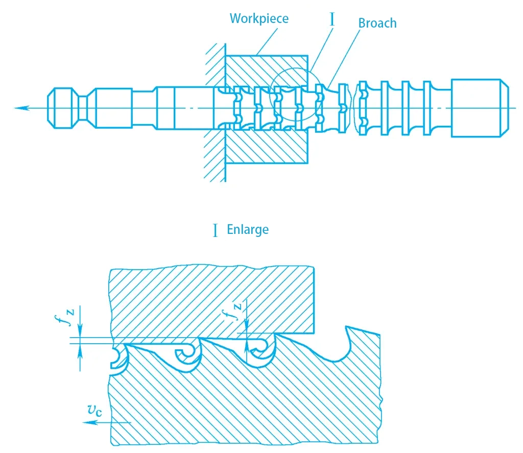
Broaching is a machining process that has only a main motion without a dedicated feed motion. During broaching, the relative motion between the broach and the workpiece is the main motion, generally a linear motion. The broach is a multi-tooth cutting tool, with each successive tooth being higher than the previous one, and the tooth profile matches the shape of the workpiece’s machined surface. The feed motion is achieved by the tooth rise (the height difference between successive teeth), as shown in Figure 13.
A rough and fine machining of the workpiece surface can be completed in one stroke on the broaching machine, that is, removing the entire allowance of the machining surface to obtain the required machining accuracy and surface quality. If the tool is subjected to pressure instead of tension during cutting, this method of machining is called push broaching, which is mainly used for finishing holes and correcting deformations of holes.
The working part of the broach has rough cutting teeth, fine cutting teeth, and calibration teeth. The workpiece machining surface undergoes rough cutting, fine cutting, and calibration in one stroke, therefore the productivity of broaching is relatively high.
The broaching speed is low, and each tooth cuts only a very thin layer of metal, resulting in a small cutting load. The manufacturing precision of the broach is very high, so the broached workpiece can achieve high accuracy, with dimensional tolerance grades reaching IT7~IT6, and surface roughness values reaching Ra3.2~0.4μm.
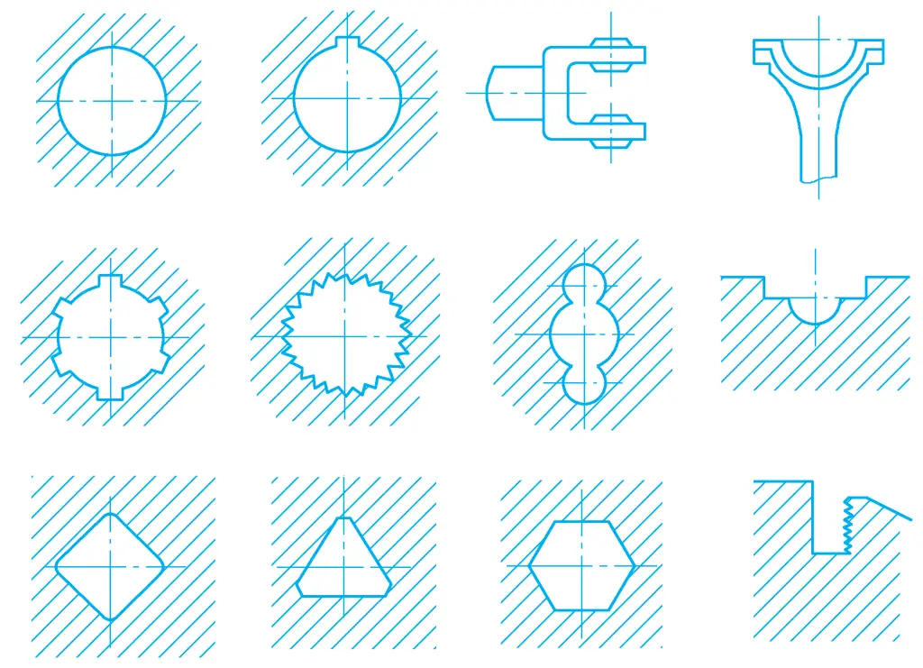
Broaches have a long service life, but their structure is complex and manufacturing costs are high, so broaching is mainly used for batch mass production. Broaching can process various shapes of through holes, planes, and formed surfaces, especially suitable for the machining of formed internal surfaces. Figure 14 shows some typical surface shapes suitable for broaching.
Common broaching machines can be divided into internal surface and external surface broaching machines according to the machining surface, and can be divided into vertical broaching machines, horizontal broaching machines, and continuous broaching machines according to the structure and layout.
Figure 15 shows the external view of a horizontal internal broaching machine. Inside the bed 1, there is a horizontally installed hydraulic cylinder 2, which drives the broach to move horizontally through the piston rod, realizing the main movement of broaching.
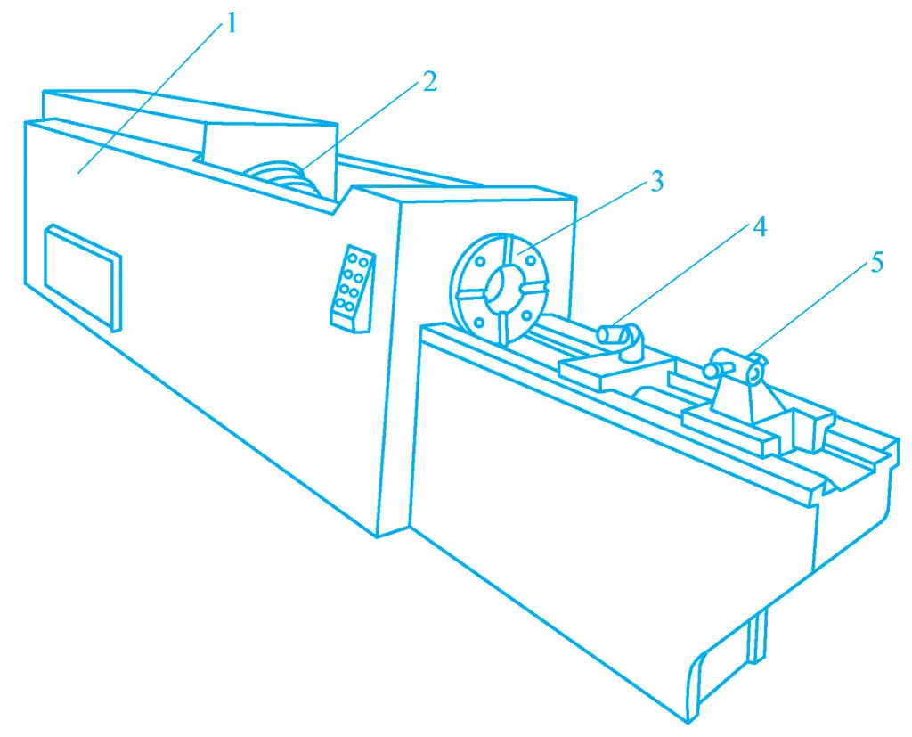
1—Bed
2—Hydraulic Cylinder
3—Support Seat
4—Roller
5—Escort Chuck
When broaching on a broaching machine, the workpiece can be positioned directly with its end face against the end face of the support seat 3 (or clamped with a fixture). The escort chuck 5 and roller 4 are used to support the broach. Before starting broaching, the escort chuck 5 and roller 4 move to the left, allowing the broach to pass through the pre-made hole in the workpiece, and the left end of the broach is inserted into the broach chuck at the front end of the piston rod. During machining, the roller 4 descends and does not function.
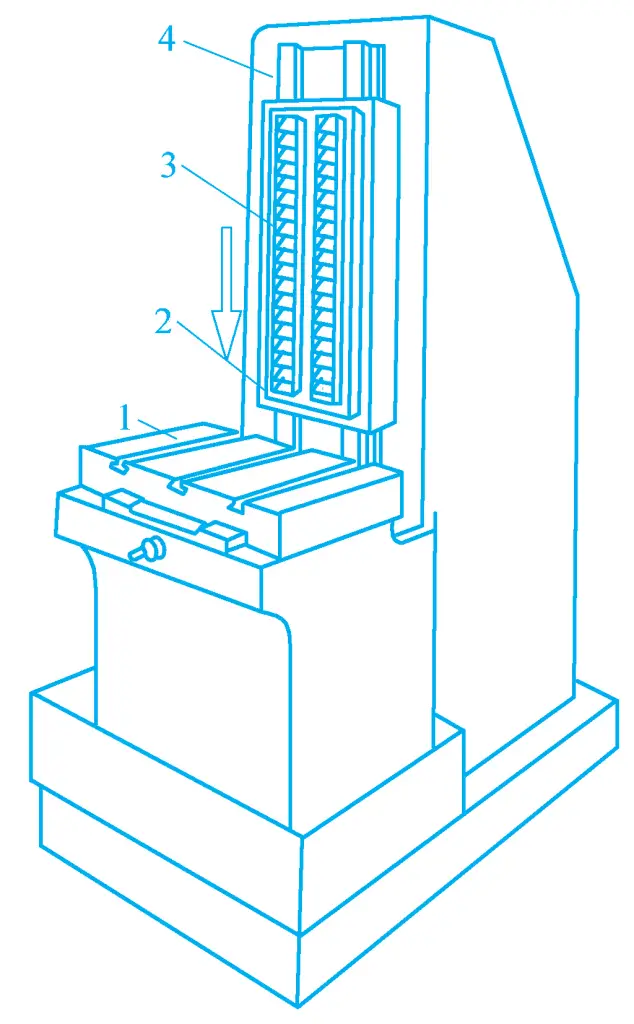
Vertical broaching machines can be divided into vertical internal broaching machines and vertical external broaching machines according to their use. Figure 16 shows the external view of a vertical internal broaching machine, which can use broaches or push broaches to machine the internal surface of the workpiece.
1—Lower Bracket
2—Worktable
3—Upper Bracket
4—Slide Seat
When machining with a broach, the workpiece is positioned with its end face tightly against the upper surface of the worktable 2, the broach is supported by the upper bracket 3 on the slide seat 4, inserted from above into the pre-made hole in the workpiece and the hole in the worktable, and its lower end handle is clamped on the lower bracket 1 of the slide seat 4. The slide seat 4 is driven by a hydraulic cylinder to move downward for broaching. When machining with a push broach, the workpiece is also mounted on the upper surface of the worktable, and the push broach is supported on the upper bracket 3, machining from top to bottom.
Figure 17 shows the external view of a vertical external broaching machine. The slider 2 can move along the vertical guide of the bed 4, and an external broach 3 is fixed on the slider 2, with the workpiece clamped in the fixture on the worktable 1. The slider moves vertically downward to complete the broaching of the external surface of the workpiece. The worktable can move laterally to adjust the back cutting amount and to retract the workpiece during the tool’s idle stroke.
1—Worktable
2—Slider
3—Broach
4—Bed body
The continuous broaching machine is a type of continuous working external broaching machine, whose working principle is shown in Figure 3-127. The chain 7 is driven by the sprocket 4 to move at the broaching speed, and multiple fixtures 6 are mounted on the chain.
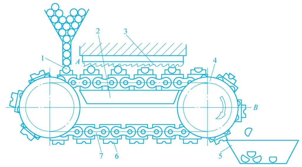
1—Workpiece
2—Guide rail
3—Broach
4—Sprocket
5—Collection box
6—Fixture
7—Chain
The workpiece is clamped at position A in the fixture, and broaching is performed when passing through the broach 3 fixed above. At this time, the fixture slides along the guide rail 2 on the bed body, and when the fixture 6 moves to position B, it automatically releases, and the workpiece falls into the finished product collection box 5. This type of broaching machine continuously processes, thus has a higher productivity, and is commonly used for mass production of small workpieces’ external surfaces, such as the processing of the connecting planes and semi-circular concave surfaces on the connecting rods of automobiles and tractors.
Broaches can be divided into internal broaches and external broaches according to the position of the surface being processed, and the commonly used internal and external broaches are shown in Figure 19.
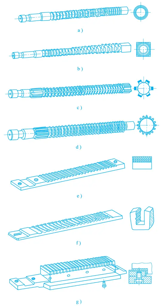
a) Round hole broach
b) Square hole broach
c) Spline broach
d) Involute gear broach
e) Flat broach
f) Tooth groove broach
g) Right angle broach
There are many types of broaches, but their structural components are basically the same. The following takes the round hole broach shown in Figure 20 as an example to explain its components and functions.
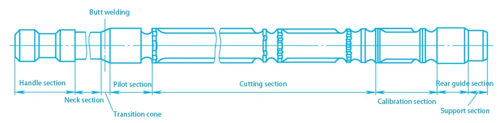
1) Shank
It is the gripping part of the broach, used to transmit the pulling force.
2) Neck
It is the connecting part between the shank and the transition cone, generally with a relatively small diameter to allow the shank to pass through the barrier of the broaching machine, and it is also the place for marking.
3) Transition cone
Used to guide the broach to gradually enter the hole of the workpiece, playing the role of aligning the center.
4) Leading section
Serves the guiding function, preventing the broach from skewing.
5) Cutting section
Responsible for all the cutting work of the remaining material, consisting of rough cutting teeth, transition teeth, and finishing teeth.
6) Calibration section
Serves the purpose of polishing and calibrating, also improves machining accuracy and surface quality, and can act as a backup for finishing teeth, with each tooth shape and size being completely identical.
7) Trailing section
Used to maintain the correct final position of the broach, preventing the broach teeth from damaging the machined surface or the teeth themselves due to sagging after cutting off.
8) Support section
Used to support the broach and prevent it from sagging. Generally, only long and heavy broaches have a support section.
The broaching method refers to the way in which the broach cuts the excess material from the workpiece, usually expressed in diagrams, hence also called broaching diagram. Whether the broaching method is reasonably devised has a great impact on the magnitude of broaching force, the distribution of tooth load, the length of the broach, the surface quality of the workpiece, the service life of the broach, productivity, and manufacturing costs.
The main broaching methods are divided into layered, segmented, and comprehensive types.
Layered broaching is a method of broaching where the excess material is cut off layer by layer in sequence. The cutting edges involved in cutting are generally longer, the cutting width is larger, there are more teeth, and the broach is longer. The productivity of layered broaching is lower, not suitable for broaching workpieces with a hard skin. Layered broaching can be further divided into:
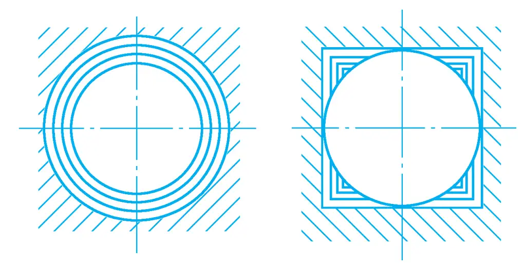
1) Contour type
The broach designed in the contour type has each tooth profile similar to the final shape of the machined surface, as shown in Figure 21. The shape and size of the workpiece surface are formed by the last finishing tooth and the calibration tooth, therefore the workpiece surface quality is relatively high.
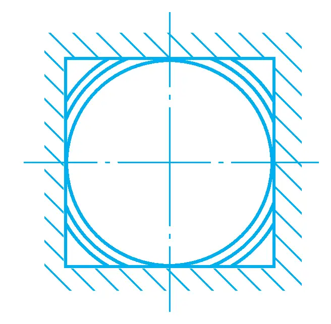
2) Progressive type
The broach designed in the progressive type has tooth profiles that are dissimilar to the shape of the surface being broached. The shape and size of the machined workpiece surface are formed by the secondary cutting edges of each tooth, as shown in Figure 22. This is suitable for machining workpieces with complex formed surfaces. The manufacturing of the broach is simpler than the contour type, but traces of the secondary cutting edge junction may appear on the already machined surface of the workpiece, resulting in poorer workpiece surface quality.
The segmented type refers to a broaching method where each layer of excess material on the workpiece is cut by a group of teeth of the same or basically the same size, with each tooth cutting only a part of the excess material, and the cutting positions of the successive teeth are staggered, with the entire excess being sequentially completed by several groups of teeth.
The broach shown in Figure 23 has four groups of cutting teeth, each group containing two cutting teeth of the same diameter, which sequentially remove the black and white parts of the metal layer. The broach designed in the segmented broaching method is called a rotary cutting broach, usually with 2 to 4 teeth per tooth group.
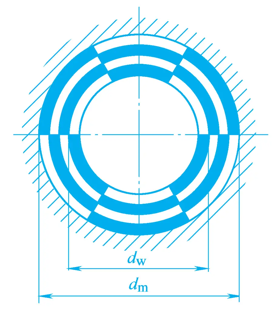
The advantage of the segmented broaching method is that the length of the cutting edge (cutting width) is shorter, the allowable cutting thickness is larger, thus the broach length can be reduced, efficiency is high, and it can directly broach workpieces with a hard skin. However, the structure of this kind of broach is complex, manufacturing is troublesome, and the surface quality of the workpiece after broaching is relatively poor.
The comprehensive type is a combination of layered and segmented broaching methods, as shown in Figure 24.
1-4—Rough cutting teeth and transition teeth
5, 6—Finishing teeth
It combines the advantages of both contour broaches and rotary cutting broaches, that is, the rough cutting teeth and transition teeth are made in a rotary cutting structure, while the finishing teeth adopt a contour structure. This can shorten the length of the broach, increase productivity, and also obtain better workpiece surface quality. The round hole broaches produced in China mostly use this structure.