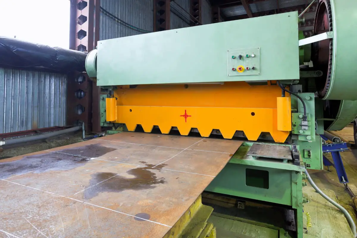
I. Cutting Process Parameters
Calculation and selection of cutting process parameters are shown in Table 1; the T/R ratio for some materials is shown in Table 2; preheating temperature for heated shearing is shown in 3; shearing conditions for different grades and specifications of materials are shown in Table 4; reasonable clearance for shearing blades is shown in Table 5.
Table 1 Calculation and Selection of Cutting Process Parameters
| Serial Number | Parameters | Calculation and Selection |
| 1 | Shear Force | When precisely selecting shearing equipment, verify the size of the shear force to ensure it is less than the tonnage of the equipment. Shear force can be calculated using the following formula F=KAτb where: – F is the shear force (N) – A is the shearing area (mm 2 ) – K is a coefficient considering factors such as blade bluntness, typically K=1.2~1.7 – τb is the material’s shear strength (10MPa), typically 0.7~0.8 times the tensile strength, i.e., τ=(0.7~0.8)R m , or refer to Table 2 for calculation |
| 2 | Shearing Temperature | For materials with higher strength (hardness) and larger cross-sectional sizes, preheat the material before shearing. The heating temperature should be: 350~550℃, see Table 3 for details. Refer to Table 4 to choose the shearing condition and decide if preheating is necessary |
| 3 | Shear gap | To ensure the quality of shearing, there should be a reasonable gap value between the upper and lower blades (see Table 5). A larger value should be used when the material hardness is high or the cross-sectional size of the sheared section is large, and a smaller value should be used otherwise. A smaller value should also be used when shearing heated. |
Table 2 Ratio of τb to Rm for some materials
| Material | τb/MPa | Rm/MPa | τ/Rm | A (%) | Note |
| Q195 | 290 | 336 | 0.86 | Annealing | |
| 375 | Cold work hardening | ||||
| Q235 | 341.7 | 423 | 0.82 | Annealing | |
| 410 | Cold work hardening | ||||
| Steel 15 | 280 | 360 | 0.74 | 32 | |
| Steel 30 | 356 | 454 | 0.79 | Annealing | |
| Steel 35 | 420 | 540 | 0.78 | Annealing | |
| Steel grades 40, 45, 50 | 460 | Annealing | |||
| Steel 75 | 610 | 1000 | 0.61 | 10.8 | |
| 30CrMnSiA | 750 | 1200 | 0.62 | 13.5 | Tempering |
| Pure copper | 160 | 200 | 0.8 | ||
| H68 | 200 | 300 | 0.66 | ||
| HPb59-1 | 260 | 420 | 0.62 | ||
| Zinc | 150 | 187 | 0.91 | ||
| 2A12 | 130 | 230 | 0.56 | 15 | Annealing |
| 2A11 | 220~240 | 380~420 | 15~20 | After hot extrusion | |
| 6A02 | 70 | 130 | 0.54 | 22 | Annealing |
Table 3 Preheat temperature for heating shear
| Material hardness HBW | 269 | 241 | 229 | 207 |
| Preheat temperature/℃ | 550 | 400 | 380 | 350 |
Note: The preheat temperature is the temperature to which the material itself is preheated.
Table 4 Shear state of materials of different grades and specifications
| Material grade | Blank diameter or side length/mm | Hardness HBW | Shear state |
| 35 Steel | ≤75 | Cold Shear | |
| 80~85 | ≥187 | Hot Shear | |
| <187 | Cold Shear | ||
| >85 | Hot Shear | ||
| 45 Steel | ≤60 | Cold Shear | |
| 65-75 | ≥207 | Hot Shear | |
| <207 | Cold Shear | ||
| >75 | Hot Shear | ||
| 40Cr | ≤50 | Cold shear | |
| 55-60 | ≥241 | Hot shear | |
| <241 | Cold shear | ||
| >60 | Hot shear | ||
| 45Cr 18CrMnTi 12Cr2NiA | ≤35 | Cold shear | |
| 40~48 | ≥255 | Hot shear | |
| ≥255 | Cold shear | ||
| >48 | Hot shear |
Table 5 Reasonable clearance for shear blades (unit: mm)
| Bar diameter | Below 20 | 20~30 | 30~40 | 40~60 | 60~90 |
| Blade gap | 0.2~1 | 0.5~1.5 | 0.8~2 | 1.5~2.5 | 2.0~3.0 |
| Bar diameter | 90~100 | 100~120 | 120~150 | 150~180 | 180~200 |
| Blade gap | 2.5~3.5 | 3~4 | 3.5~5 | 4.5~8 | 7~12 |
II. Shear bed cutting blade
1. Blade type
The blades of the shear bed consist of two pieces, one fixed on the lower die seat and the other mounted on the upper template, driven by the slider to move up and down to achieve shearing. The types of blades seen in production are varied. The characteristics of single and multi-slot blades are shown in Table 6, and the characteristics of single and double-edged blades are shown in Table 7.
Table 6 Characteristics of single and multi-slot blades
| Blade | Type | Simplified Diagram | Characteristics |
| Single-slot blade | Integral type | 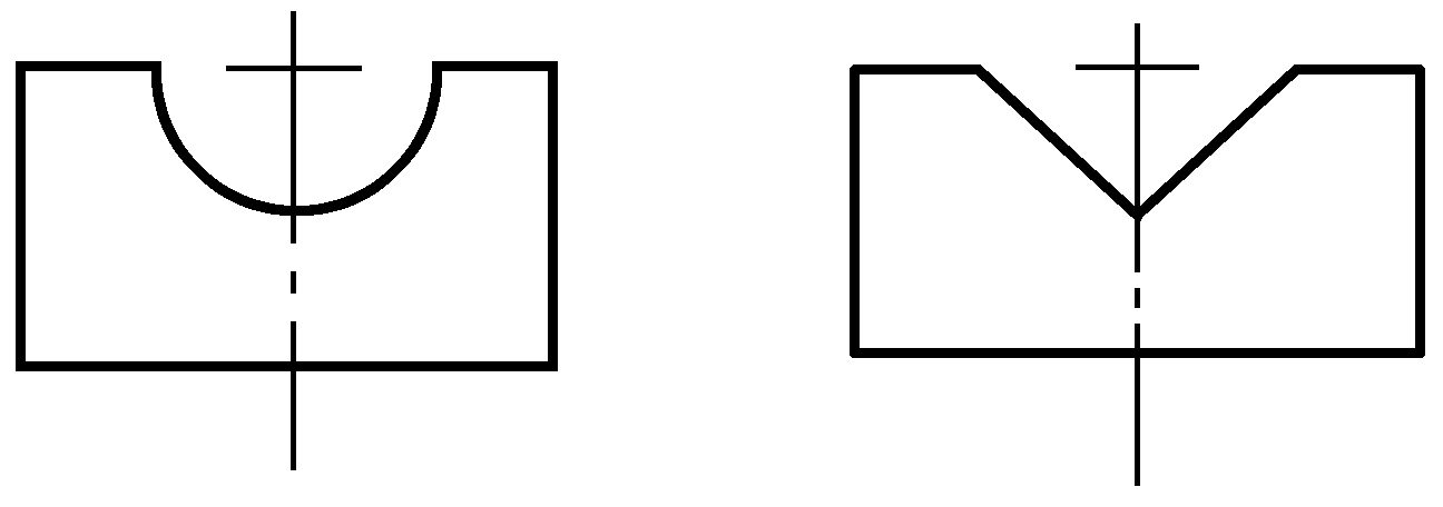 | Both the upper and lower blades of the shears are open type |
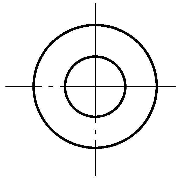 | The lower blade is a closed type blade, which prevents the bar from bending, used for cutting small bars, while the upper blade (moving blade) is still made open type | ||
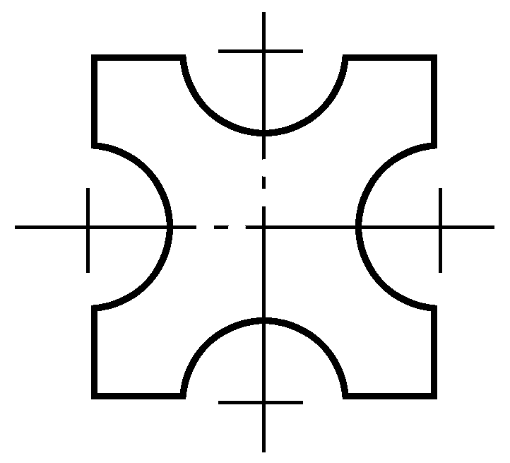 | The blade has cutting edges on all four sides, improving the utilization rate of the blade | ||
| Insert type |  | Can save some tool steel, but requires an additional blade holder | |
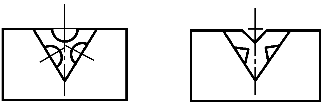 | Same advantages and disadvantages as above, additionally can be used on three sides | ||
| Combination type | 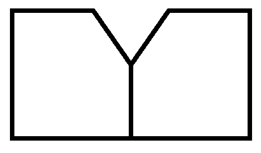 | Can avoid stress concentration at the corners of the integral blade, improving blade life, but also requires a blade holder | |
| Multi-groove blade | Same shape and size |  | Can cut two bars at once, improving productivity, used for large equipment to cut small materials |
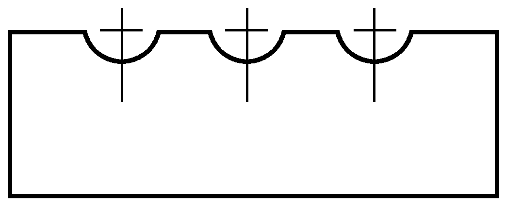 | As above, can cut three pieces at once | ||
| Same shape, different sizes |  | Can cut multiple blanks of different sizes at once | |
| Different shapes and sizes |  | Can cut multiple blanks of different shapes and sizes at once | |
| Enclosed type | 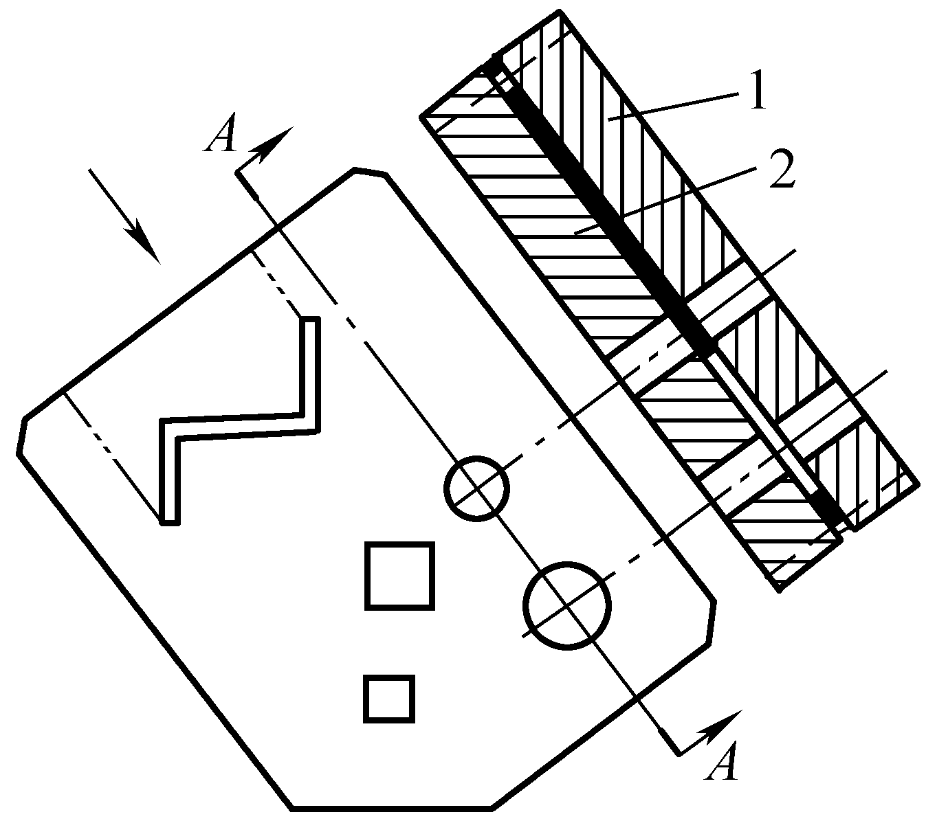 | Without changing the blade, it can cut steel of different shapes and sizes, used on an ironworker machine. In the diagram, 2 is the moving blade, 1 is the stationary blade |
Table 7 Characteristics of single and double-edged blades
| Blade | Simplified Diagram | Characteristics |
| Single-edged blade |  | Can reduce the lever arm, but when cutting, the blade presses deeper into the bad material, affecting the end face quality, and can only be used on one side |
| Double-edged blade |  | Can be used on both sides, better end face quality |
2. Blade design
When designing blades, the following two conditions are mainly considered: equipment process specifications, and the shape and size of the material being cut.
(1) Circular blade
Circular blade design is shown in Table 8.
Table 8 Circular blade design
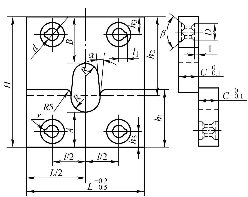
- R—Edge radius
- h 1 — Lower blade height
- h 2 — Upper blade height
- A— Distance from the bottom of the lower blade edge to the bottom of the blade
- B— Distance from the top of the upper blade edge to the top end of the blade
| No. | Parameters | Calculation and selection |
| 1 | Edge radius R | The edge radius mainly depends on the diameter of the rod being cut; too large an R can overly flatten the cross-section of the rod, sometimes even causing cracks If R is less than half the diameter of the rod being cut, the rod’s side will have indentations, affecting the blade’s lifespan The radius of the blade edge can also refer to Table 9, which is found by the diameter of the rod being cut |
| 2 | Lower blade size A | Take empirical data from equipment process specifications 5000kN shearing machine, A=120~130mm 10000kN shearing machine, A=130~140mm |
| 3 | Upper blade size B | The smaller the value of B, the better, under the condition of ensuring blade strength and multiple regrindings, it can be determined by the following formula B=H-[S+A+(0.3~0.32)Dmin ] Where H is the height of the shear bed blade opening (mm) S is the stroke of the shear bed (mm) |
| 4 | Height of upper and lower blades h 1 and h 2 | The blade edge height of the upper and lower blades should be equal. It can be determined by the following formula h 1 =(H+A-B)/2 + (7~10)mm h 2 =H-h 1 +(15~20)mm |
| 5 | Blade external dimensions | Blade thickness C: Mainly considering the strength and stiffness of the blade, can be selected C = (0.25 to 0.5)D where D is the diameter of the rod being cut (mm) Blade thickness C, blade width L, can also be selected according to the tonnage of the equipment, see Table 2-18 The inclination angle α at the blade opening can be taken as 10° |
| 6 | Bolt holes | Bolt holes for fixing the blade, generally 4 holes, i.e., 2 holes for the moving blade, 2 holes for the fixed blade; in some cases, 6 holes. Hole diameters d and D, center distances l, l 1 , h 3 , and dowel pin slot radius r, all related to the tonnage of the equipment, see Table 10 |
Table 9 Blade edge radius (unit: mm)
| Rod diameter D | 28~32 | 34~36 | 38~42 | 45~50 | 54~56 | 60~65 |
| Edge radius R | 17 | 19 | 22.5 | 26.5 | 29.5 | 34.5 |
| Bar diameter D | 70~75 | 80~85 | 90~95 | 100 | 110 | 130 |
| Edge radius R | 39.5 | 44.5 | 50 | 53 | 58 | 68 |
Table 10 Dimensions of round inserts (unit: mm)
| Equipment tonnage/kN | d | D | l | l1 | h3 | r | c | L |
| 5000 | 36 | 55 | 230 | 22 | 55 | 5 | 60 | 419 |
| 10000 | 48 | 72 | 260 | 27 | 60 | 6 | 80 | 479 |
(2) Square edge blades
Square steel is generally sheared along the diagonal, and the blades are divided into integral and combined types. See Table 11 for the design of integral square edge blades.
Table 11 Design of integral square edge blades

| No. | Parameters | Calculation and selection |
| 1 | Lower Blade Size A | Take empirical data according to the equipment For 5000kN and 10000kN shears, 110~120mm can be taken |
| 2 | Upper Blade Size B | B = H – [s + A + 0.7a min ] Where H—height of shear blade opening (mm), obtained from equipment process specifications s—stroke of the shear (mm), refer to equipment process specifications a min —the minimum side length of the square material cut by the same blade (mm), the maximum allowable side length of the square material to be cut Should be within the following range a max ≤ 1.25a min |
| 3 | Lower blade height h 1 | h 1 = (H + A – B) / 2 + (7 ~ 10) mm |
| 4 | Upper blade height h 2 | h 2 = H – h 1 + (15 ~ 20) mm |
| 5 | Die slot fillet radius r | To prevent stress concentration and damage to the blade during shearing, a fillet must be used at right angles, see Table 12 |
| 6 | Blade profile dimensions | The determination of the blade profile dimensions is the same as for circular edge blades |
| 7 | Bolt holes | The design and related dimensions of bolt holes are as per the design of circular edge blades |
Table 12 Die slot fillet radius r (unit: mm)
| Square material side length a | <50 | 50~70 | 75~90 | 90~105 | 110~125 | 130~150 |
| Fillet radius r | 7 | 9 | 12 | 15 | 15 | 21 |
(3) Flat edge blade
The blades for cutting flat steel can be made with a flat edge, as shown in the attached figure in Table 13. Type I, both upper and lower blades have grooves, used for cutting thick materials; Type II, the upper blade does not have grooves, i.e., B equals h 2 , often used for cutting thinner materials. Both types cut along the wide edge of the flat material.
Table 13 Flat Edge Blade Design
| Type I Blade Dimensions | Type II Blade Dimensions | ||
| Diagram | 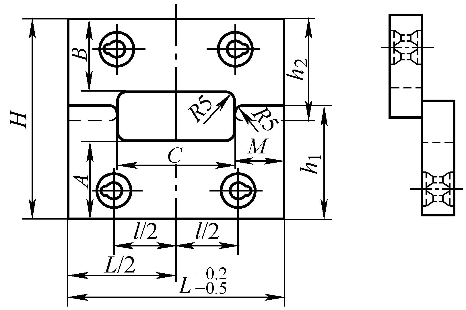 | 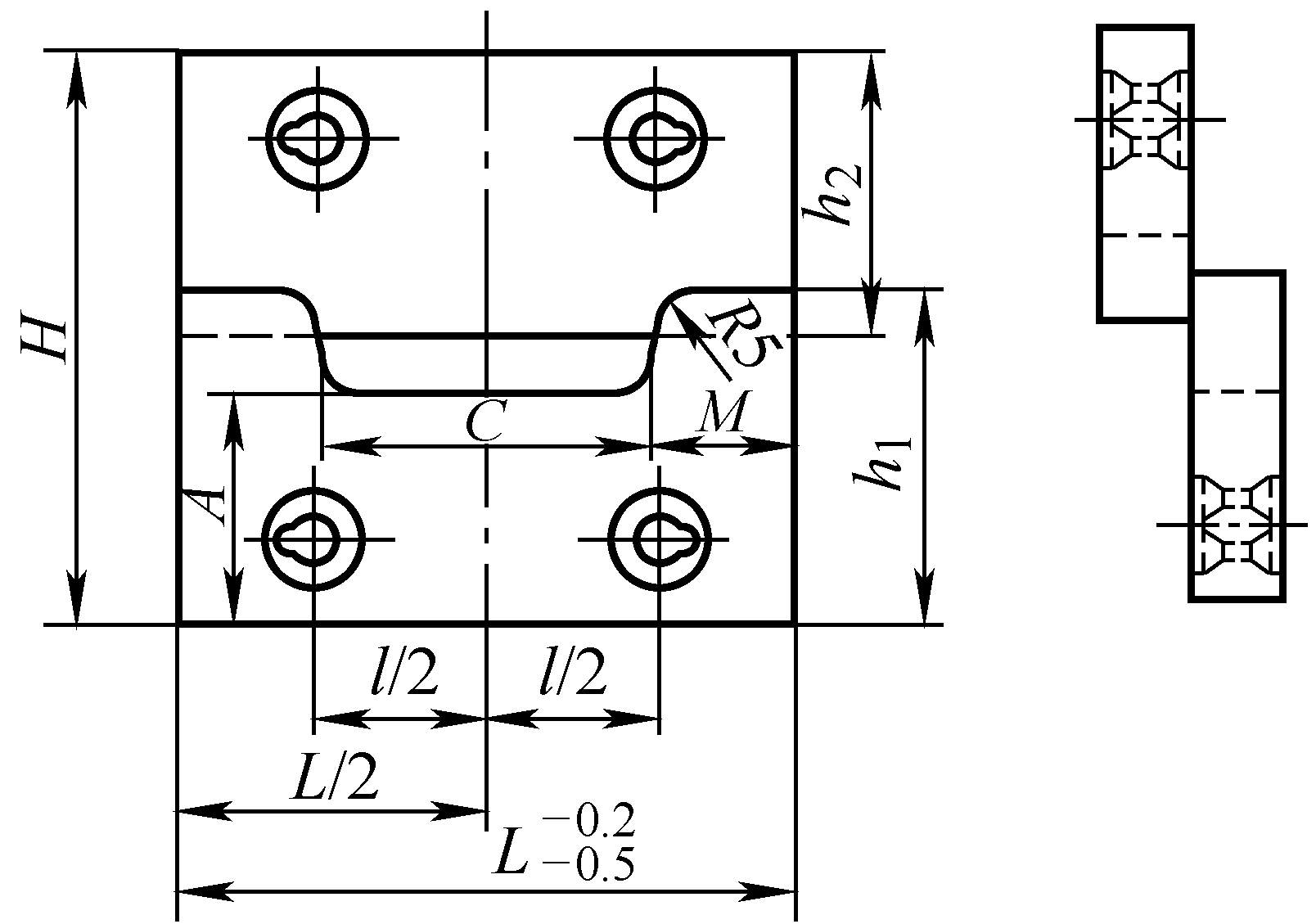 | |
| No. | Parameters | Calculation and Selection | |
| 1 | Lower Blade Size A | Take empirical data based on equipment tonnage 5000kN shearing machine, A = 175mm 10000kN shearing machine, A = 190mm | Type II Blade and Type I The only difference is the upper blade does not have a groove, that is B equals h 2 . Regarding dimensions, determination as above |
| 2 | Upper blade size B | The upper blade (moving blade) edge should be below the lower blade edge at the bottom dead center of the stroke, can be determined by the following formula B = H – S – A + (5 to 10) mm | |
| 3 | Edge length C | The length of the edge is mainly determined by the size of the flat steel being cut, for convenience During grinding, the material should be slightly wider than the measurement C = bwidth + (20~30) mm M = (L – C) / 2 mm | |
| 4 | Upper and lower blade heights h 2 and h 1 | h1=(H+A-B)/2 + 10mm h2=H-h1+20mm | |
| 5 | Blade dimensions | The determination of the dimensions is the same as for circular blade edges | |
| 6 | Bolt holes | The design and relevant dimensions of bolt holes are shown in the circular blade edge design | |
3. Blade fasteners
Blade fasteners mainly include bolts, locating pins, and nuts, designed based on equipment tonnage, see Table 14 and Table 15.
Table 14 Bolt and locating pin dimensions
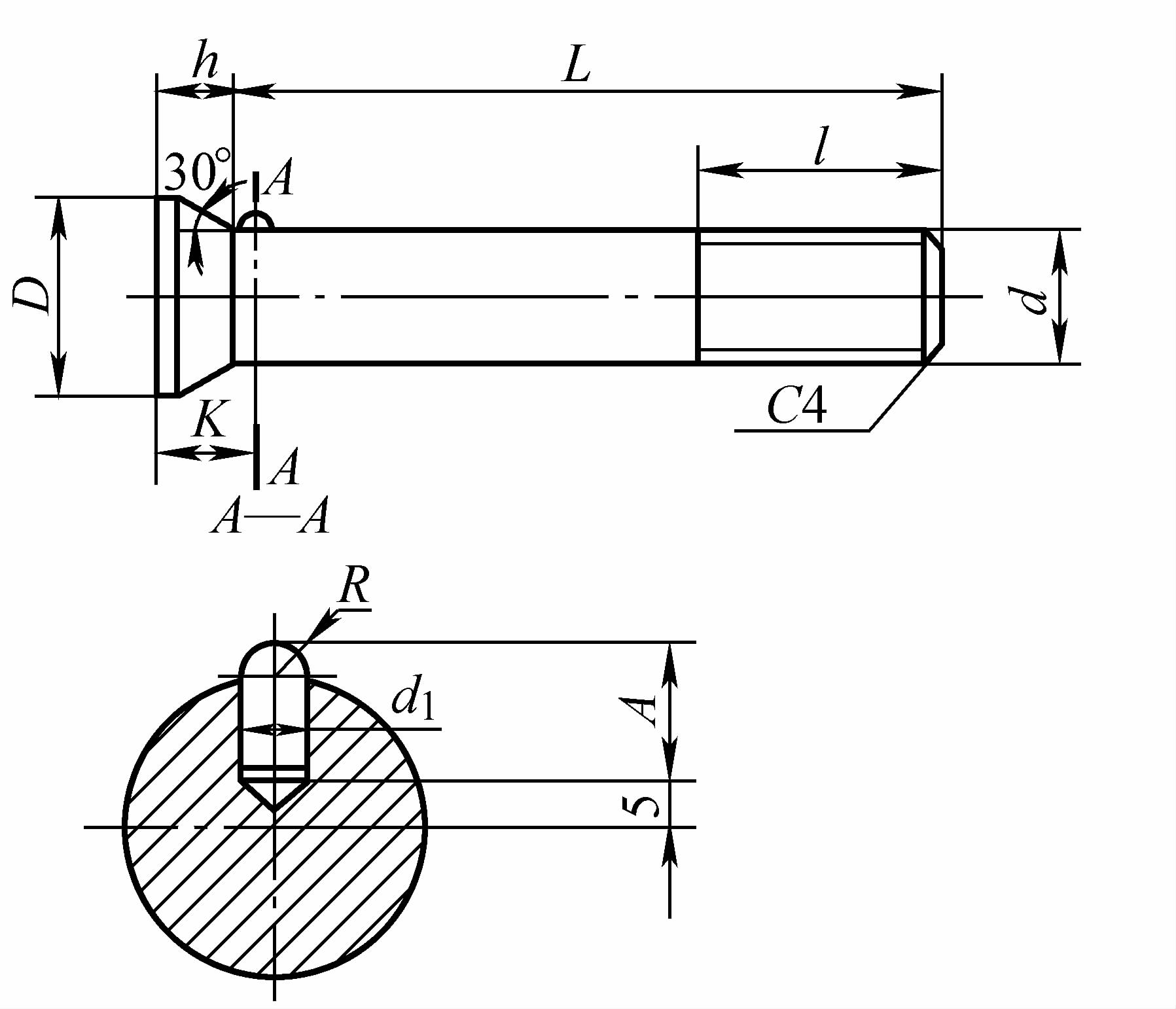
| Shearing machine tonnage | Bolt | Bolt and locating pin size/mm | ||||||||
| d | L | l | h | D | K | A | R | d1 | ||
| 5000kN | Upper bolt | M33 | 200 | 70 | 20 | 52 | 25 | 17 | 4.5 | 9 |
| Lower bolt | M33 | 260 | 70 | 20 | 52 | 25 | 17 | 4.5 | 9 | |
| 10000kN | Upper bolt | M42 | 270 | 90 | 28 | 70 | 34 | 26 | 5.5 | 11 |
| Lower bolt | M42 | 360 | 90 | 28 | 70 | 34 | 26 | 5.5 | 11 | |
Table 15 Nut dimensions
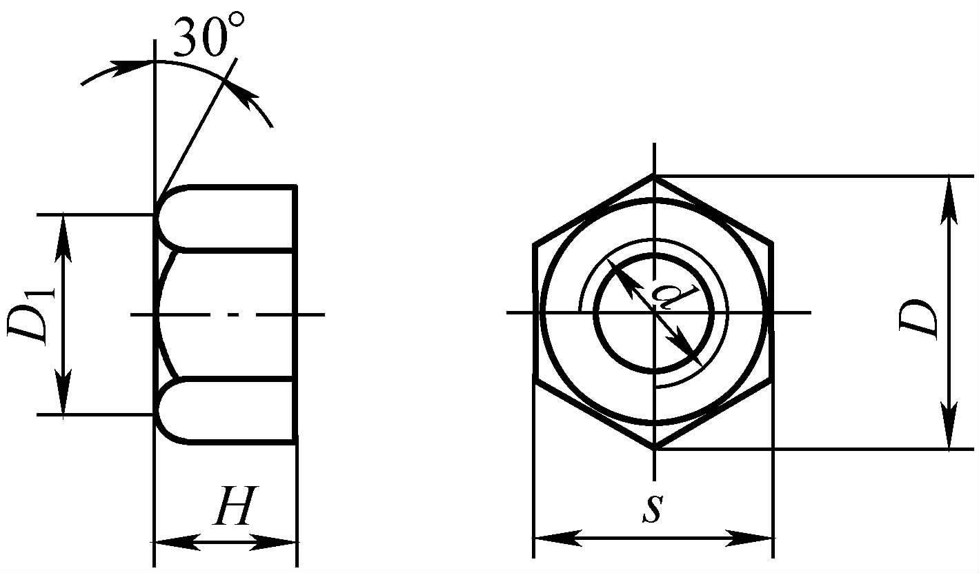
| Shearing machine tonnage/kN | Nut size/mm | ||||
| d | H | s | D | D1 | |
| 5000 | 1M33 | 30 | 50 | 57.8 | 47 |
| 10000 | 1M42 | 35 | 70 | 80.8 | 66 |
4. Blade material
During the cutting process, the blade suffers severe wear, so the material used to make the blade must have high wear resistance, and its hardness should be more than twice that of the material being cut. For hot shearing blades, a certain level of hot hardness is also required, meaning that the blade must retain the necessary hardness at the shearing temperature.
When specifically choosing, factors such as the size of the blade and the grade of the material being cut must also be considered. The hardness and applications of materials for cold and hot shearing blades are shown in Table 16 and Table 17.
Table 16 Hardness and Application of Cold Shearing Blade Materials
| Material | Heat Treatment Hardness HRC | Application | |
| Carbon tool steel | T7, T8 | 58~62 | Used for small blades, and produced in small batches |
| T9, T10 | 58~62 | ||
| Alloy tool steel | Cr, 9SiCr | 58~62 | Used for large blades, mass production in batches |
| CrWMn | 60~62 | ||
| 7Cr3, 8Cr3 | 50~55 | ||
| Cr12Mo, Cr12MoV | 58~62 | ||
Table 17 Hardness and Application of Hot Shearing Blade Materials
| Material | Heat Treatment Hardness HRC | Application |
| 5CrMnMo | 42~45 | Used for batch mass production with cutting temperatures above 200℃ |
| 5CrNiMo | 45~47 | |
| 3Cr2W8V | 45~48 | |
| 5CrW2Si | 45~50 | |
| 6CrW2Si | 45~50 | |
| T7, T8, T9, T10 | 55~60 | Used for small blades and small batch production with cutting temperatures below 150℃ |
III. Specifications and Production Capacity of Shearing Equipment
Specifications of shearing equipment are shown in Table 18 and Table 19. Shearing production capacity is shown in Table 20 and Table 21.
Table 18 Specifications of Special Shearing Equipment
| Equipment Name | Model | Maximum Shearing Capacity/mm | |
| Diameter of Round Steel | Square steel side length | ||
| Ironworker machine | Q34—10 | Φ35 | 28 |
| Q34—16 | Φ45 | 40 | |
| Q34—16A | Φ38 | 35 | |
| Q34—25 | Φ65 | 55 | |
| Bar shearing machine (Crank shear bed) | Q42—250 | Φ90 | — |
| Q42—500 | Φ132 | 125 | |
| 10000kN | Φ190 | 180 | |
| 12500kN | Φ210 | 185 | |
| 16000kN | Φ250 | 220 | |
| Billet shearing machine | QA95-100 | Φ50 (cold shear) | 50 (cold shear) |
| — | 150 (hot shear) | ||
Table 19 Q42 type bar shearing machine technical parameters
| Technical parameters | Model | ||||
| Q42-250A | Q42-500 | QA42-500 | QA42-500A | Q42-1000A | |
| Maximum Shearing Force/kN | 2500 | 5000 | 5000 | 5000 | 10000 |
| Maximum Shearing Diameter/mm | Φ100 (When R m ≥450MPa) | Φ132 (When R m ≥450MPa) | Φ105 (When R m ≥700MPa) | p115 (When R m ≥620MPa) | Φ190(R m ≥450MPa when) |
| Number of Strokes/(times/min) | 30 | 18 | 38 | 38 | 16 |
| Stroke Height/mm | 80 | 100 | 90 | 90 | 140 |
| Material Stop Range/mm | 55 ~500 | 110 ~1000 | 65~500 | 65~500 | 120 ~1000 |
| Motor Power/kW | 17 | 30 | 40 | 30 | 75 |
Note: The equipment listed in the table is produced by Shenyang Forging Machine Tool Factory.
Table 20 Shearing Production Capacity (I) (Unit: pcs/h)
| Blank Diameter/mm | Different billet lengths/mm | |||||||||||
| 100 | 200 | 300 | 400 | 600 | 800 | 1000 | 1200 | 1400 | 1600 | 1800 | 2000 | |
| Φ20 | 2100 | 1600 | 1400 | 1250 | 800 | 720 | 650 | 590 | 380 | 340 | 300 | 270 |
| Φ30 | 1900 | 1400 | 1350 | 1150 | 760 | 680 | 600 | 540 | 360 | 320 | 290 | 260 |
| Φ40 | 1500 | 1200 | 1100 | 1000 | 660 | 600 | 540 | 490 | 320 | 290 | 260 | 230 |
| Φ50 | 1300 | 1000 | 900 | 800 | 520 | 470 | 420 | 380 | 250 | 220 | 200 | 180 |
| Φ60 | 1050 | 800 | 720 | 650 | 430 | 390 | 350 | 320 | 210 | 200 | 170 | 150 |
| Φ70 | 900 | 700 | 630 | 550 | 360 | 330 | 300 | 270 | 180 | 160 | 140 | 130 |
| Φ80 | 800 | 600 | 540 | 480 | 320 | 290 | 260 | 240 | 160 | 140 | 130 | 120 |
| Φ90 | 650 | 500 | 450 | 400 | 260 | 230 | 210 | 190 | 130 | 120 | 110 | 100 |
| Φ100 | 450 | 350 | 310 | 280 | 180 | 160 | 140 | 130 | 90 | 80 | 70 | 65 |
| Φ110 | 300 | 370 | 250 | 160 | 140 | 130 | 120 | 80 | 70 | 65 | 60 | |
| p120 | 250 | 230 | 210 | 140 | 130 | 120 | 110 | 70 | 60 | 55 | 50 | |
| Φ130 | 200 | 180 | 160 | 110 | 100 | 90 | 80 | 55 | 50 | 45 | 40 | |
| Φ140 | 150 | 130 | 120 | 80 | 70 | 60 | 55 | 35 | 30 | 27 | 25 | |
| Φ150 | 110 | 90 | 80 | 50 | 45 | 40 | 35 | 25 | 23 | 21 | 20 | |
Note: The data in the table should be reduced by 20% during hot shearing.
Table 21 Shearing Production Capacity (II) (Unit: kt/a)
| Equipment Name | Average mass of billet/kg | ||||||
| 0.25~0.6 | 0.6~1.0 | 1.0~1.6 | 1.6~2.5 | 2.5~4.0 | 4.0~6 | ||
| Crank shear bed | Cold cut 1 piece simultaneously | — | — | — | 10 | 12 | 15 |
| Cold cut 2 pieces simultaneously | — | — | — | 15 | 18 | 22 | |
| Hot cut 1 piece simultaneously | — | — | — | 8 | 10 | 12 | |
| Hot cut 2 pieces simultaneously | — | — | — | 12 | 15 | 18 | |
| Ironworker machine | — | 4 | 5.2 | 6.5 | 8.5 | 11 | |
| Crank press | 1.3 | 2.3 | 4 | — | — | — | |
| Sawing machine | 0.06 | 0.08 | 0.1 | 0.14 | 0.21 | 0.27 | |
| Equipment name | Average mass of blank/kg | ||||||
| 6 to 10 | 10 to 16 | 16 to 25 | 25 to 40 | 40 to 60 | 60 to 100 | ||
| Crank shear | Simultaneous cold cutting of 1 piece | 18 | 22 | 26 | 31 | 36 | 43 |
| Simultaneous cold cutting of 2 pieces | 27 | 33 | 39 | 45 | 54 | — | |
| Simultaneous hot cutting of 1 piece | 14 | 18 | 21 | 24 | 29 | 34 | |
| Simultaneous hot cutting of 2 pieces | 22 | 26 | 31 | 36 | 43 | — | |
| Ironworker machine | 14 | 18 | 23 | 27 | — | — | |
| Crank press | — | — | — | — | — | — | |
| Sawing machine | 0.4 | 0.48 | 0.6 | 0.9 | — | — | |

