Best Ironworker Machines: Top Brands and Features Compared
In the world of metalworking, choosing the right ironworker machine can make all the difference between a seamless operation and…

In industrial sectors that use metal sheets extensively, it is necessary to cut the sheets according to size requirements, making the shearing machine the most widely used sheet cutting equipment in various industrial sectors.
In recent years, the research and production of shearing machines in China have developed rapidly, with continuous updates in structure and a gradually complete range of varieties and specifications. From small to large, the shearing size from 1mm×1000mm to 40mm×4000mm has formed a complete series of shearing machine parameter standards, with the largest specification having produced a 50mm×3200mm mechanical transmission shearing machine.
To meet the special needs of the industry, wide shearing machines of 13mm×16000mm and rolling shears of 25mm×12000mm have been produced, and the level of design and manufacturing has been continuously improved. In addition to the development of mechanical transmission for small and medium-sized shearing machines according to user needs, since the 1960s, hydraulic transmission has been gradually adopted for medium and large shearing machines.
In addition, swing beam shearing machines, straight and bevel two-purpose shearing machines, and sheet bending and shearing machines have all been developed accordingly, and their structures are continuously being improved to enhance shearing precision and automation level, in order to expand their range of use and improve production efficiency.
The shearing machine belongs to the category of straight-line shearing machines, mainly used for shearing the straight edges of various sizes of metal sheets. Using the rear or front material stop device, the sheet metal can be sheared to a fixed length. When the rear material stop plate is lifted, shearing of any length can be performed. Most of the machine body is equipped with a throat, within the depth of which wide strips can be continuously sheared.
The angle shearing device set on the workbench can shear the plate at an angle, so wherever metal plates are produced or used, such as in steel rolling, automobiles, airplanes, ships, tractors, locomotive vehicles, bridges, electrical appliances, instruments, boilers, pressure vessels, and other industrial sectors, shearing machines are used without exception.
There are many types of shearing machines, which can be divided according to their process use and structural type:
The shearing quality is relatively good, with little torsional deformation. Mechanical transmission is more common, mostly used for small shearing machines.
Includes guillotine shearing machines and swing beam shearing machines. The shearing quality is worse than the former, with torsional deformation, but the force and energy consumption are smaller than the former, suitable for medium and large shearing machines. The main transmission system uses hydraulic transmission and mechanical transmission. The guide rail types include sliding guide rails and rolling guide rails. This structural form is the most produced and widely used.
Swing beam shearing machine, divided into straight shearing type and both straight and inclined shearing type, the latter mainly used for shearing 30° welding bevels. The main transmission system has hydraulic transmission and mechanical transmission, with the former being produced more.
Plate bending and shearing machine, that is, two processes can be completed on the same machine, with the lower part of the machine performing plate shearing, and the upper part performing bending, and some machines perform shearing at the front and plate bending at the back.
Plate and profile shearing machine, that is, on the upper and lower tool holders of the shearing machine, one side is equipped with a blade for shearing plates, and the other side is equipped with a blade for shearing profiles.
Pneumatic shearing machines are mostly used on shearing lines, with fast speed and high number of shears. Foot-operated shearing machines are used for shearing thin plates and narrow plates. In the slanting blade shearing machine, the mechanical transmission can be divided into gear transmission and worm gear transmission.
According to the type of crankshaft, it can be divided into long crankshaft (or eccentric shaft) transmission and eccentric shaft vertical elbow rod type. In the mechanical downward transmission form, it can be divided into lower shaft transmission and side shaft transmission. In hydraulic transmission, there are single cylinder, double cylinder in series, and double cylinder in parallel, etc.
The CNC shearing machine as shown in Figure 1. It is generally on the body of a common guillotine or swing beam shearing machine, equipped with a fast automatic positioning control system for the backgauge, driven by an AC servo motor and a ball screw transmission variable speed drive device, ensuring the accuracy of the backgauge size, improving the shearing accuracy and production efficiency.
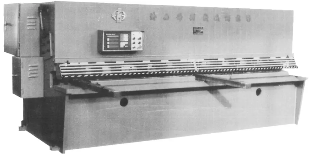
The CNC system used can program control the backgauge, blade gap, and shearing angle, and can be equipped with an electronic display device. A laser alignment device is set at the front of the machine tool, making the beam concentrated and clear.
Some CNC shearing machines cancel the backgauge device and have a CNC front feeding table in front of the hydraulic swing beam shearing machine. The material to be sheared is placed on the feeding table, clamped by hydraulic clamps, automatically fed in, automatically positioned according to the programmed settings, and coordinated with the movement of the upper tool holder of the shearing machine for single positioning shearing or continuous automatic shearing, which can greatly improve the shearing accuracy and reduce labor intensity.
The CNC shearing machine can be equipped with electromagnetic suction rollers and stacking devices to realize the automation of material discharging. The control system uses a special CNC system for shearing machines, with simple programming, stable and reliable performance, complete functions, and convenient operation.
The model of the shearing machine is established according to the “Forging Machinery Model Preparation Method”, with the main parameters represented by shear thickness × plate width. The series parameters of shear thickness are based on the preferred number series R5 and R10, taking into account the thickness standards of steel plates produced in China.
The shear width is determined by referring to the standard width of steel plates produced, combined with the requirements of the using factory and the series situation of similar shearing machines abroad. The technical parameter standards for shearing machines established in our country are shown in Table 1.
Table 1 Basic Parameters of Shearing Machine
| Shearable Thickness t/mm | Shearable Width b/mm | Rated Shear Angle α | Number of Strokes / (times/min) | |
| No-load Operation | Full Load | |||
| 1 | 1000 | 1° | 100 | 40 |
| 1250 | ||||
| 2.5 | 1250 | 1° | 65 | 30 |
| 1600 | ||||
| 2000 | ||||
| 2500 | ||||
| 3200 | ||||
| 4 | 2000 | 1°30′ | 60 | 22 |
| 2500 | ||||
| 3200 | 55 | 20 | ||
| 4000 | ||||
| 6 | 2000 | 1°30′ | 50 | 18 |
| 2500 | ||||
| 3200 | 14 | |||
| 4000 | ||||
| 5000 | — | 12 | ||
| 6300 | ||||
| 8 | 2000 | 1°30′ | 50 | 14 |
| 2500 | ||||
| 3200 | 45 | 12 | ||
| 4000 | ||||
| 5000 | — | 10 | ||
| 6300 | ||||
| 10 | 2000 | 2° | 45 | 12 |
| 2500 | ||||
| 3200 | 40 | 10 | ||
| 4000 | ||||
| 5000 | — | 8 | ||
| 6300 | ||||
| 12 | 2000 | 2° | 40 | 10 |
| 2500 | ||||
| 3200 | 35 | 8 | ||
| 4000 | ||||
| 5000 | — | |||
| 6300 | ||||
| 16 | 2000 | 2°30′ | 30 | 8 |
| 2500 | ||||
| 3200 | ||||
| 4000 | ||||
| 5000 | — | 6 | ||
| 6300 | ||||
| 20 | 2000 | 2°30′ | 20 | 6 |
| 2500 | ||||
| 3200 | ||||
| 4000 | ||||
| 5000 | — | 5 | ||
| 6300 | ||||
| 25 | 2000 | 3° | 20 | 5 |
| 2500 | ||||
| 3200 | ||||
| 4000 | ||||
| 5000 | — | 4 | ||
| 6300 | ||||
| 32 | 2500 | 3°30′ | 15 | 4 |
| 3200 | ||||
| 4000 | ||||
| 5000 | — | 3 | ||
| 6300 | ||||
| 40 | 2500 | 3°30′ | 15 | 3 |
| 3200 | ||||
| 4000 | ||||
Note:
1. The selected plate material should have σ b ≤ 450MPa.
2. For hydraulic transmission shearing machines, only the number of full-load strokes is specified.
3. The throat depth should generally be chosen as 0, 100, 300, 500mm.
There are many manufacturers of shearing machines in China, and each manufacturer, according to the basic parameter standards set by the country, combined with their own factory’s product structure characteristics and market needs, has also developed their own factory’s series of parameter tables. Due to fierce competition, there are also quite a variety of product developments and specifications.
The development situation of the main technical parameters of shearing machines produced domestically and abroad is described as follows:
Around the 1960s, shearing machines capable of cutting plate thicknesses up to 60mm were produced abroad, and China also produced shearing machines with a cutting thickness of 50mm.
With the development of science and technology, the cutting process of plates has also been continuously improved. In recent years, shearing machines capable of cutting thicknesses up to 40mm have become rare. Considering the utilization rate and economy of the equipment, the maximum cutting thickness of shearing machines produced by most countries is 25mm or 32mm.
With the development of heavy trucks, trailers, large buses, and large aircraft, the demand for increasing shearing width continues to grow. Shearing machines with a cutting width of up to 9000mm, 10000mm have been produced abroad. Shearing machines with a cutting width of 6000mm have been relatively commonly produced.
With the continuous improvement of product quality, the requirements for the shearing quality and production efficiency of sheet metal are also increasing. The process of shearing long strips on shearing machines can no longer compete with other cutting technologies, so the method of using deep-throat shearing machines to shear long strips is rarely seen.
In addition, the throat depth significantly affects the weight of the machine, so currently, both domestic and foreign produced shearing machines tend to adopt a smaller throat depth, especially in large-scale shearing machines, it is more obvious. To accommodate users’ special requirements, in the series, except for a few specifications that have an enlarged throat, generally, a shallow throat is adopted, and a deep throat is handled through special orders.
In order to reduce the bending and twisting of the sheared sheet, a smaller shearing angle is generally adopted, which may increase the shearing force somewhat, and also have some impact on the strength and stiffness of the stressed components, but it improves the shearing quality.
The number of strokes is directly related to production efficiency. With the development of production, the emergence of various loading and unloading devices requires the machine to have a higher number of strokes. For mechanical transmission small shearing machines, it generally reaches more than 50 times per minute. Hydraulic transmission shearing machines also consider the hydraulic system and control aspects to enable them to automatically and quickly adjust the stroke length according to the width of the sheared plate, in order to increase the number of strokes.
Since the output of sheet metal occupies a large proportion in the steel production of each country, and many industrial sectors use sheet metal, therefore, in every industrially developed country, there are many factories that produce shearing machines according to their own series of parameter standards.
The main technical parameters of some CNC shearing machines are shown in Table 2.
Table 2 Main technical parameters of CNC shearing machines
| Name | QS11K-4×2500 | QS-11K-6×2500 | QC12K-4×2500 | QC12K-6×2500 | QC12K-6×3200 | |
| Cuttable thickness/mm | 4 | 6 | 4 | 6 | 6 | |
| Cuttable width/mm | 2500 | 2500 | 2500 | 2500 | 3200 | |
| Shearing angle | 1°18′ | 1°30′ | 1°30′ | 1°30′ | 1°30′ | |
| Backgauge stroke/mm | 750 | 750 | 600 | 600 | 600 | |
| Stroke frequency/(times/min) | 60 | 60 | 22 | 22 | 17 | |
| Main motor power/kW | 5.5 | 7.5 | 5.5 | 7.5 | 7.5 | |
| Transmission type | Mechanical underdrive clutch type | Hydraulic swing beam type | ||||
| Number of CNC axes | 1 | |||||
| Rear stopper adjustment maximum speed/(m/min) | 5 | |||||
| Rear stopper adjustment positioning accuracy/mm | ± 0.10 | |||||
| Machine dimensions/mm | Long | 3590 | 3670 | 3080 | 3130 | 3840 |
| Width | 3200 | 1830 | 1440 | 1530 | 1675 | |
| Height | 1560 | 1610 | 1550 | 1600 | 1620 | |
| Machine weight/t | 5.5 | 6 | 4 | 5 | 6.6 | |
Note: The strength of the sheared plate α b ≤450MPa.
The shearing machine works by applying shearing force to metal plates of various thicknesses using a moving upper blade and a fixed lower blade, with a reasonable blade gap, causing the plates to fracture and separate according to the required dimensions, as shown in Figure 2.
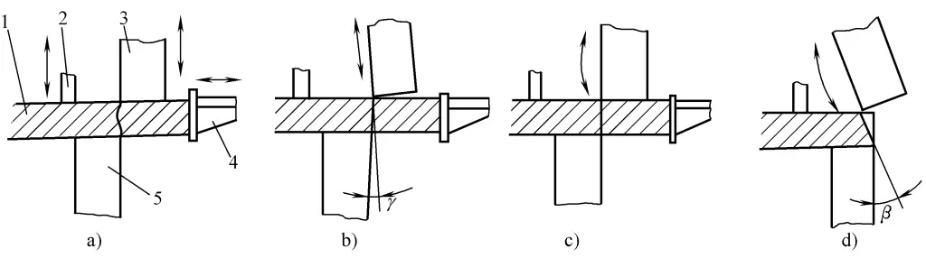
a) The upper blade moves up and down in the vertical plane
b) The upper blade moves up and down in the plane with a forward angle γ
c), d) The upper blade swings along a circular arc surface
1—Metal sheet
2—Presser
3—Upper blade
4—Rear stop rack
5—Lower blade
In order to improve the shearing quality and expand the process range, the moving blade of the shearing machine has different forms of motion, described as follows:
(1) The upper blade moves up and down in a vertical plane (guillotine type).
(2) The upper blade moves up and down in an inclined plane (forward-tilting upper blade type).
(3) The upper blade swings along an arc surface (swing type), capable of shearing straight edges, or shearing both straight and beveled edges, that is, cutting out the welding bevel angle β, as shown in Figure 2d.
The structure of the upper blade moving up and down in a vertical plane is more commonly used. The forward-tilting motion of the upper blade is an improvement on the basis of the vertical plane motion, which is beneficial to improve the shearing quality, and a four-edge blade can be used to increase the blade life. The forward tilting angle γ is mostly between 1° to 2.5°, with angles greater than 3° being less common.
The main drive system of the shearing machine includes mechanical transmission, hydraulic transmission, and pneumatic, with hydraulic transmission being more commonly used. For small-scale mechanical transmission shearing machines, due to reasons such as higher stroke frequency, simple maintenance, and ease of mastering the operation of the machine, manufacturers both domestic and abroad still produce them.
In mechanical transmission shearing machines, cylindrical gear transmission is more commonly used, which includes upper transmission and lower transmission types. In the upper transmission type, as shown in Figure 3, the motor 5 drives the flywheel shaft through the V-belt 6, then through the clutch 7 and the gear reduction system 4 drives the eccentric shaft, which then through the connecting rod drives the upper tool post 2, making it perform up and down reciprocating motion, to carry out the shearing work.
1—Press beam
2—Upper tool post
3—Press tank
4—Gear reduction system
5—Electric motor
6—V belt
7—Clutch
8—Brake
9—Presser foot
10—Workbench
11—Machine body
The cam on the left end of the eccentric shaft drives the plunger in the pressurized oil tank 3, sending the pressurized oil to the presser foot 9, clamping the plate material before shearing. On the return, the presser foot is retracted by the tension of the spring.
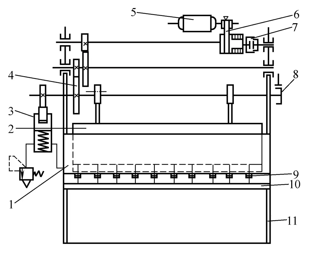
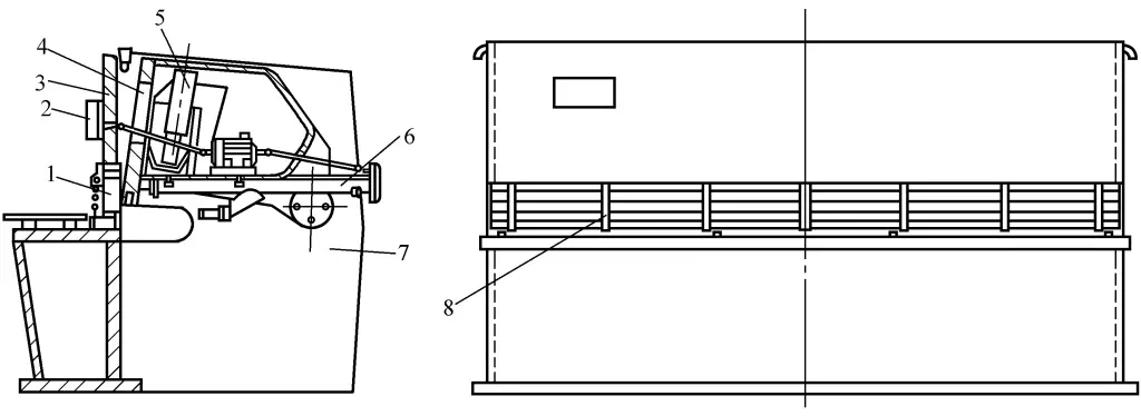
The mechanical down-drive shearing machine, as shown in Figure 4, has a compact structure, low machine body height, low center of gravity, better stability, smaller part sizes, and is relatively easy to manufacture and install. It is generally used on small shearing machines with a plate thickness of less than 6mm, and less so on large specifications.
1—Clamping oil tank
2—Eccentric shaft
3—Clamping foot
4—Clamping beam
5—Upper tool carrier
6—Lower tool carrier
7—Gear transmission system
8—Brake
9—Clutch
10—Coupling
11—Flywheel
12—Motor
13—Connecting rod
14—Body
In the mechanical transmission shearing machine, worm gear drive is also used, as shown in Figure 5. The motor drives the flywheel shaft through a V-belt drive, the flywheel shaft is equipped with a worm, which drives the worm wheel, the worm wheel drives the eccentric shaft to rotate, and then drives the upper tool post to move up and down reciprocally through the connecting rod to perform the shearing work. A cam and a clamping hydraulic cylinder are installed at the left end of the eccentric shaft. The transmission ratio of the worm gear drive is large, it operates smoothly, with less noise, but lower efficiency, it is still used in medium and small size shearing machines.
1—Clamping beam
2—Upper tool post
3—Clamping oil tank
4—Cam
5—Eccentric shaft
6—V belt drive
7—Worm gear drive
8—Electric motor
9—Presser foot
10—Lower tool post
11—Brake
12—Clutch
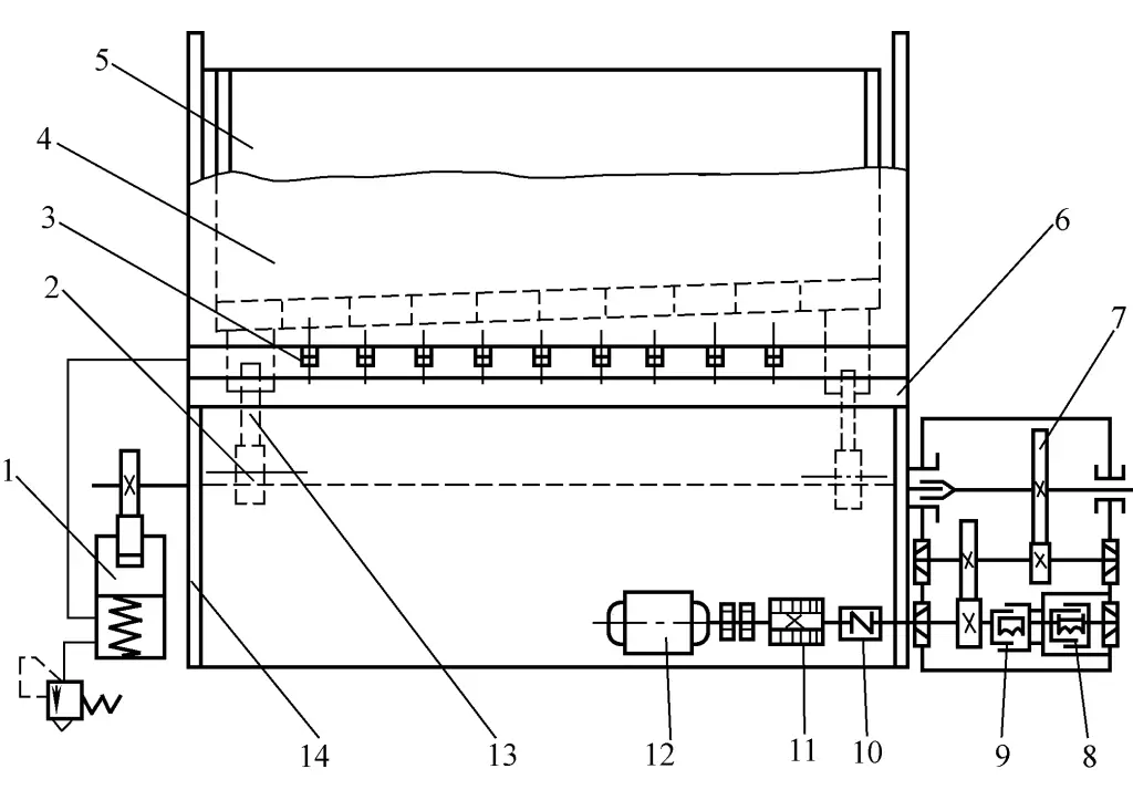
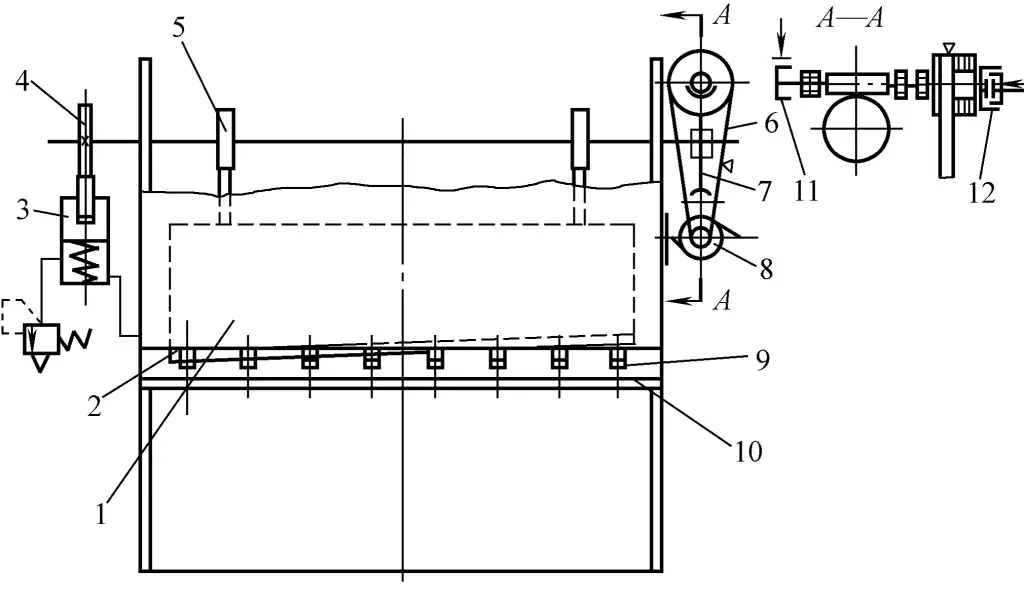
The production of hydraulic transmission shearing machines is increasing, with the structure shown in Figure 6. The main features are that the shearing force remains constant throughout the entire stroke, it is safe to work, has a high degree of generalization, is lighter in weight, does not require the manufacturing of large transmission components, is easy to adjust some parameter values and achieve automation, but has a lower number of strokes, and faults are not as easy to detect and eliminate as with mechanical transmission shearing machines.
1—Hold-down foot
2—Backgauge counter
3—Hold-down beam
4—Swinging upper knife frame
5—Main hydraulic cylinder
6—Backgauge
7—Machine body
8—Safety cover
In both hydraulic and mechanical transmission shearing machines, there has been the development of swing beam shearing machines where the upper knife frame moves along an arc surface. Swing beam shearing machines eliminate the inherent guide mechanism of guillotine shearing machines, saving the processing and maintenance of the guide surface.
The adjustment of the gap between the blades is achieved by using the eccentric shaft at the pivot point of the tool holder, which has a simple structure and is convenient to adjust. The synchronous movement of both ends of the upper tool holder can be achieved by the strong rigidity of the tool holder itself, eliminating the corresponding control device in the hydraulic system. Since the upper blade of the swing beam shearing machine moves along an arc surface, the cutting edge can automatically leave the edge of the plate during shearing, reducing the wear on the blade.
Ordinary shearing machines generally consist of the body, transmission device, tool holder, presser, rear stop rack, front stop rack, balancer, material support device, blade gap adjustment device, light alignment device, lubrication device, electrical control device, and other components, with the main components structured as follows:
The body generally consists of left and right columns, workbench, and crossbeam. For old-fashioned shearing machines, the body is mostly made of cast iron parts, which are fastened together with bolts and pins, combining the workbench, crossbeam, and left and right columns. This type of composite structure body is heavier, has poorer rigidity, and requires more machining on the joint surfaces, so the use of cast iron parts has gradually decreased.
With the advancement of processing technology, the use of integral steel plate welded structures for medium and small shearing machines has been increasing. Welded bodies are lighter in weight, have good rigidity, and are aesthetically pleasing, so they are used more frequently. For large shearing machines, due to their large external dimensions, a combined welded structure is more commonly used for ease of processing.
The tool holder is an important part of the shearing machine. Old-fashioned small shearing machines mostly use cast iron parts for the tool holder, while large ones use cast steel parts. In recent years, the use of steel plate welded structures has been increasing.
Figure 7 shows the tool holder structure of the Q12-6.3×2500 type shearing machine. One end of the tool holder 6 is hinged to the body through the eccentric sleeve 7 and the fixed shaft 9, and the other end is driven by the crankshaft 1 and the connecting rod 3. When the crankshaft rotates, the slider swings around the pivot point to achieve the shearing action. The upper blade 5 is fixed on the arc-shaped blade seat, ensuring an even gap between it and the lower blade.
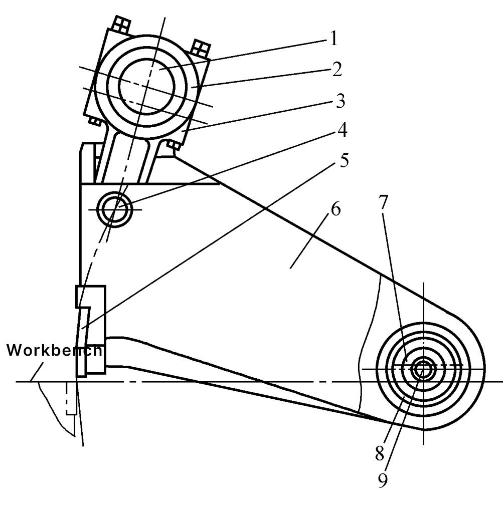
1—Crankshaft
2—Connecting rod cap
3—Connecting rod
4—Pin
5—Upper blade
6—Tool holder
7—Eccentric sleeve
8—Bearing
9—Fixed shaft
The transmission systems of shearing machines commonly include mechanical transmission systems and hydraulic transmission systems.
Common mechanical transmission systems include gear transmission and worm gear pair transmission, as shown in Figures 3 and 5, that is, a first-level V-belt, a second-level gear transmission, and a first-level V-belt, a first-level worm gear pair transmission. There are also two-level gear transmissions or a first-level V-belt, a first-level gear transmission.
Figure 8 shows the hydraulic schematic of a 32×4000mm swing beam shearing machine with a dual-cylinder parallel connection. After the electric motor 1 starts, the plunger pump 2 outputs hydraulic oil, one route flows towards the overflow valve 3, the pressure gauge 9, and the other route returns to the tank through the check valve 4 and the electro-hydraulic directional valve 5. When the solenoid valve on the left end of the electro-hydraulic directional valve is energized, the hydraulic oil in the control circuit pushes the hydraulic valve core to move right, and the hydraulic oil in the main circuit enters the clamping hydraulic cylinder, clamping the plate material.
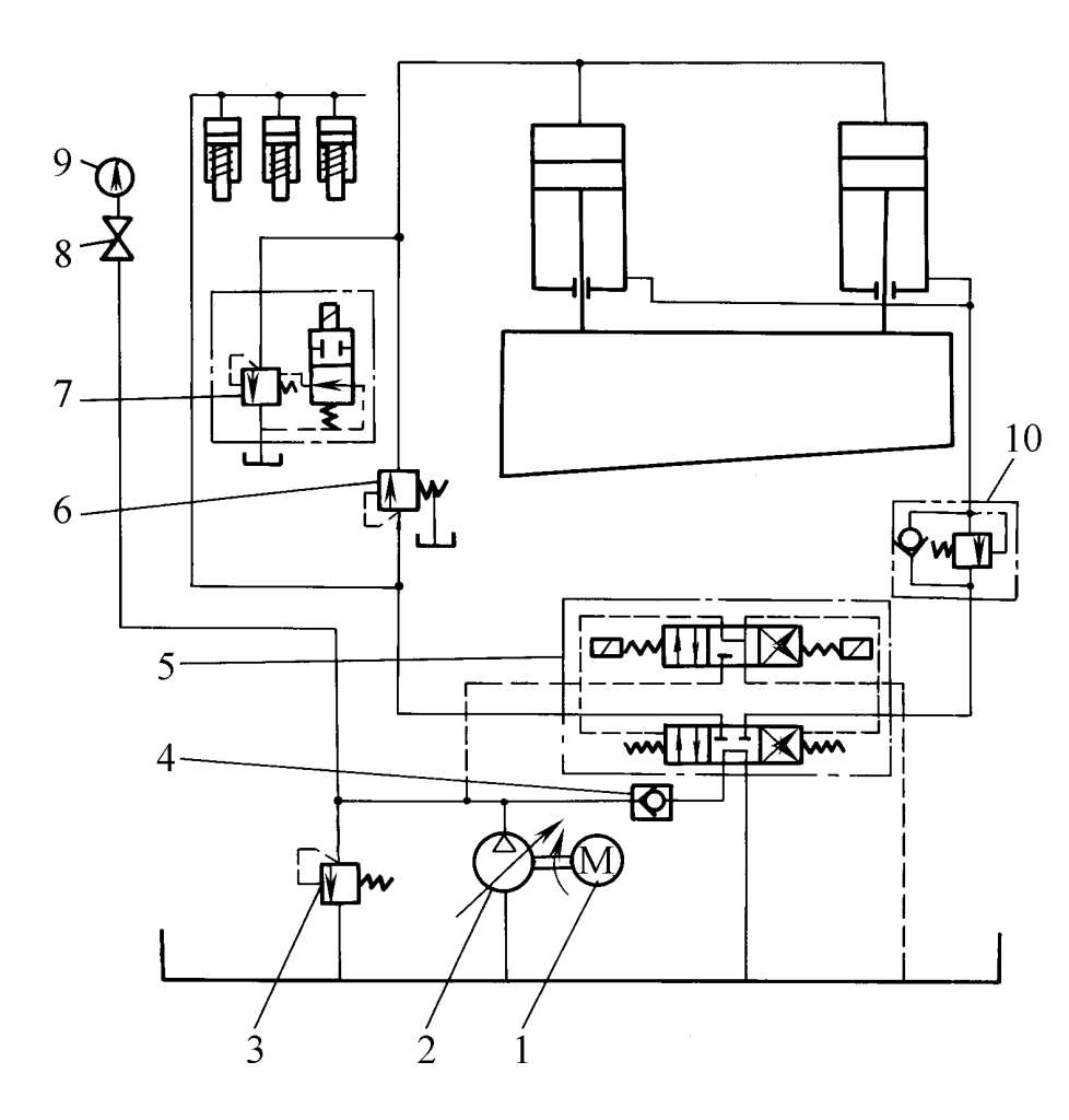
1 – Electric motor
2 – Axial piston pump
3 – Overflow valve
4 – Check valve
5 – Electro-hydraulic directional valve
6 – Directly controlled sequence valve
7 – Electromagnetic overflow valve
8 – Pressure gauge switch
9 – Pressure gauge
10 – Direct control balance valve
When a certain pressure is reached, the direct control sequence valve 6 opens, the solenoid valve 7 is energized, and the hydraulic oil enters the upper chamber of the left and right hydraulic cylinders, causing the tool post to move downward and shear the plate. After the oil in the lower chamber reaches a certain pressure, it returns to the tank through the direct control balance valve 10 and the hydraulic valve.
After the shearing is completed, the left end of the solenoid valve is de-energized and the right end is energized, controlling the hydraulic oil to push the hydraulic valve core to move left, the main oil path oil enters the lower chamber of the hydraulic cylinder through the check valve inside the direct control balance valve, the solenoid valve 7 is de-energized, the oil in the upper chamber and the oil in the pressurizing cylinder return to the tank, the tool post moves upward, and the presser foot also moves upward under the tension of the spring, returning to the original position. The right end of the solenoid valve is de-energized, the control oil path is blocked, the hydraulic valve core resets, and the next shearing cycle begins.
In front of the blade on the shearing machine, there is a presser that keeps the plate material always pressed on the worktable surface during the entire shearing process. The pressing force generated by the presser must be able to overcome the rotational torque caused by the shearing force on the plate material, keeping the various forces acting on the plate material in balance during the shearing process, to prevent displacement or flipping of the plate material during shearing. Therefore, the presser is also an important load-bearing component.
The pressers on shearing machines have mechanical transmission, hydraulic transmission, pneumatic, electromagnetic suction, and other types. In small-scale shearing machines, these structural forms are all adopted, among which mechanical transmission and hydraulic transmission are used more. In recent years, due to the increased requirements for shearing precision, the selected pressing force has also shown a trend of increase, and the use of hydraulic transmission pressers has become more and more common.