Comprehensive Guide to Sheet Metal Forming Processes and Equipment
Imagine a world without the sleek curves of a car’s body or the precise angles of an airplane wing—such is…
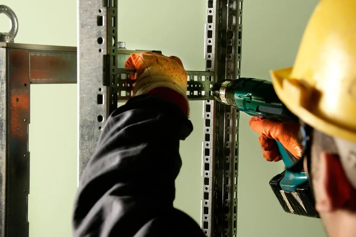
Currently, our company primarily utilizes sheet metal components as the main structure. We have summarized the common connection methods and specifications for sheet metal parts to facilitate design reference and improve efficiency. The main connection methods for sheet metal parts include:
1.Screw connection 2.Pull riveting 3.Pull bolt riveting 4.Hook and slot connection 5.Spot welding 6.Hinge connection 7.TOX clinching
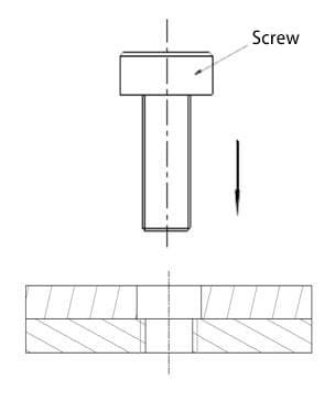
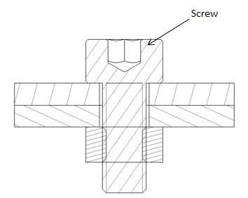
Principle: In the two connected parts, one part has a threaded hole, and the other part has a corresponding through hole. Finally, they are connected using a screw (as shown in Figure 1); or both parts have through holes, and they are connected using a bolt and nut (as shown in Figure 2).
Advantages:
Can be assembled and disassembled multiple times, and relatively easy to assemble and disassemble.
Disadvantages:
1. Quality issues may arise, such as poor quality screws, difficulties in ensuring the quality of tapping and threading holes, thread slippage leading to part rejection or screw loosening, and other potential issues.
2. The number of screws is relatively high, requiring more manpower, leading to high costs and low efficiency.
Applicable Scope:
Parts connections in machines that require disassembly (such as the threaded hole on the KCPLUS reinforcement rib connecting to the antenna).
Common methods:
1.Self-tapping screws
2.Tapping + screw connection
3.Riveted stud/nut + screw
4.Screw + nut
Principle:
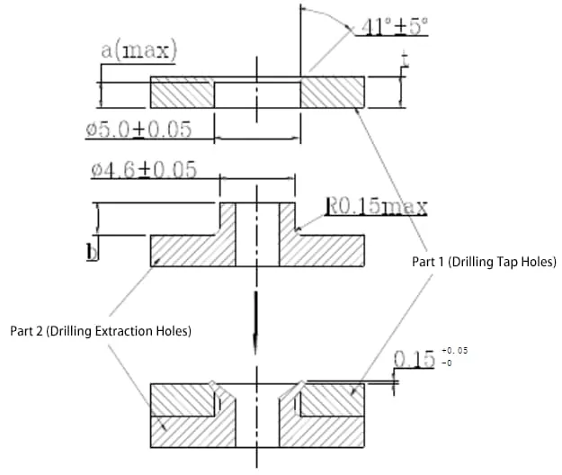
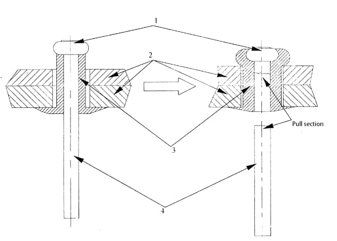
As shown in Figure 3, part 1 (with a punched hole) and part 2 (with a drawn hole) are matched. A mold is used to expand the drawn hole, filling the corner hole of the punched hole, thereby connecting the two parts into a single unit.
Advantages:
1. No need to add parts, resulting in high riveting strength.
2.High production efficiency when using a mold for riveting.
Disadvantages:
1. Difficult to ensure quality.
2.It is a one-time connection and cannot be disassembled.
Applicable Scope:
1. Connections of stamped parts that do not require disassembly.
2. Connections within the stamped part itself.
Specifications:
The specifications for punch riveting are related to the material thickness of the part with the punched hole (such as part 1 in Figure 3). Different material thicknesses have different specifications. Below are the specifications based on the material thickness of the part with the punched hole (0.9, 1.2, 1.5mm), as shown in Table 1. For detailed specification dimensions, refer to Figure 3.
| Material thickness (mm) Parameters (mm) | 0.9 | 1.2 | 1.5 |
| a(max) | 0.5 | 0.8 | 1 |
| b | 1.5 | 1.7 | 2 |
Principle:
As shown in Figure 4, insert the rivet into the corresponding holes of the two parts, use a rivet gun to pull the pulling rod 4 (until it breaks), the head 1 of the rod moves downward, causing its outer rivet sleeve 3 to expand outward, larger than the diameter of the hole, thereby achieving the purpose of connecting the two parts.
Advantages:
1.Only need to create rivet holes on the parts, simple structure. 2.Good connection quality. 3.(Because the riveting action can be completed by the supplier), low labor cost.
Disadvantages:
1.After connection, the head has a certain height, and the back of the connection surface cannot be completely flat.
2.Disassembly is inconvenient after connection.
Scope of application:
Mainly used for connecting stamped parts and non-removable component connections.
Specifications:
Rivets are divided into two types: flat head rivets and countersunk head rivets (as shown in Figure 5). Flat head rivets are mainly used for surfaces with high requirements where there should be no protruding connections. The flat head of the rivet is embedded in a 120° countersunk hole on the stamped part, keeping the head flush with the surface. Some of the specification parameters for the rivet and the rivet hole are shown in Table 2.
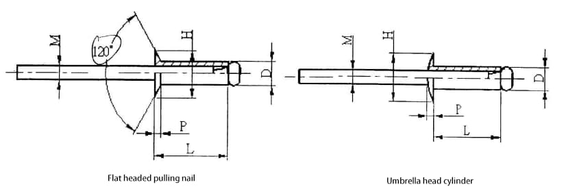
Table 2: Rivet and Rivet Hole Specifications
| Rivet Types | D | Rivet Hole Diameter | Rivet Thickness | L | H | P | M | Shear strength | Tensile strength | ||
| Countersunk Head | Flat Head | Countersunk Head | Flat Head | Ultimate strength (N) | |||||||
| Aluminum Alloy Steel Core Pull Rivet | 2.4 | 2.5 | 1.0~3.2 | 1.6~3.2 | 5. 7 | 4.8 | 0.7 | 0.8 | 1.42 | 490 | 735 |
| 3.2~4.8 | 3.2~4.8 | 7. 3 | |||||||||
| 4.8~6.4 | 4.8~6.4 | 8. 9 | |||||||||
| 3 | 3.1 | 1.0~3.2 | 1.6~3.2 | 6.3 | 6 | 0.9 | 1.0 | 1.83 | 735 | 1180 | |
| 3.2~4.8 | 3.2~4.8 | 8. 0 | |||||||||
| 4.8~6.4 | 4.8~6.4 | 9.8 | |||||||||
| 3.2 | 3.3 | 1.6~3.2 | 1.6~3.2 | 6.3 | 6.4 | 0.9 | 1.1 | 1.83 | 930 | 1420 | |
| 3.2~4.8 | 3.2~4.8 | 8 | |||||||||
| 4.8~6.4 | 4.8~6.4 | 9.8 | |||||||||
| 4 | 4.1 | 1.2~3.2 | 1.6~3.2 | 6. 9 | 8 | 1.2 | 1.4 | 2.28 | 1470 | 2210 | |
| 3.2~4.8 | 3.2~4.8 | 8.6 | |||||||||
| 4.8~6.4 | 4.8~6.4 | 10.4 | |||||||||
| 4.8 | 4.9 | 1.6~3.2 | 2.3~3.2 | 6.9 | 9.6 | 1.4 | 1.6 | 2.64 | 2260 | 3240 | |
| 3.2~4.8 | 3.2~4.8 | 9.3 | |||||||||
| 4.8~6.4 | 4.8~6.4 | 11.1 | |||||||||
Note:
1. Except for the limit strength cover position which is Newton (N). The remaining cover positions are in millimeters (mm).
2. The size positions shown in the table are shown in Figure 5
Principle:
Spot welding is generally divided into two categories: double-sided spot welding and single-sided spot welding. In double-sided spot welding, the electrodes feed power to the welding point from both sides of the workpiece. The typical double-sided spot welding method is the most commonly used, where there are electrode impressions on both sides of the workpiece.
Using a conductive plate with a large welding area as the lower electrode can eliminate or reduce the impressions on the lower workpiece.
Advantages:
1. Spot welding provides secure fastening, is completed by suppliers, and is fast and economical;
2. Parts do not require complex structures.
Disadvantages:
It has certain requirements for the shape of the parts. This issue should be carefully considered during the design phase, and this method can be considered for connecting larger parts with ample space.
Characteristics:
The hook and slot interlocking method generally serves a pre-positioning function and cannot directly fasten parts. It is commonly used in conjunction with locking screws, rivets, and other fastening methods.
Structural Description:
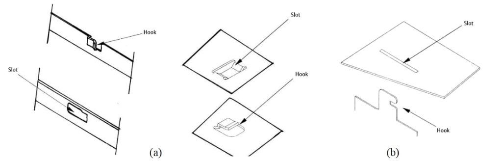
The structure of the hook and slot interlocking connection includes hooks and slots. In the hook forms listed in Figure 6 (a) and (b) below, the hooks and slots do not correspond one-to-one. They can be paired in an alternating manner as needed. The hook form listed in Figure 6 (b) is used for connections that do not require very strong fastening.
Specifications: Due to the relatively less secure positioning provided by the hook and slot interlocking method, and its common use in conjunction with other connection methods, its specific specifications are flexible and adaptable, with loose fitting requirements. The specifications shown in Figure 7 can be referenced during design and are suitable for various forms of hook and slot interlocking connections.
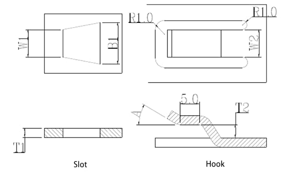
W2 = 6.0mm or 10.0mm (usually 6.0 for smaller parts, 10.0 for larger parts), W1 = W2 + 0.3, B1 = W2 + 3.0, T1 = thickness to be clamped, T2 = T1 + 0.1, A = 20
Note: Length unit is mm
Advantages:
1. The connected parts can rotate around the axis, making disassembly and assembly convenient;
2. Convenient and quick to purchase
Disadvantages:
More parts involved, higher cost.
Principle:
Through strong tension and compression, the material undergoes plastic deformation, embedding one workpiece material into another workpiece material, thereby connecting two sheet metal parts using a stamping process, as shown in Figure 8.
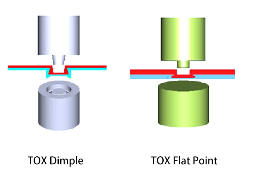
Table: TOX Connection Point Diameter Optimum Series
| Connection Point Diameter | 6mm | 8mm | 10mm |
| Single Sheet Thickness Range | 0.5-1.75 | 1.0-2.5 | 1.25-3.0 |
| Shear Strength (N) | 1000-2500 | 2600-3600 | 3000-6000 |
| Tensile Strength (N) | 1000-2700 | 2100-4000 | 3000-5000 |
| Stamping Force (kN) | 20-45 | 35-50 | 60-80 |
| Punching Die Ejection Force (N) | 500-3500 | 1000-6000 | 2000-8000 |
For non-detachable connections, it is recommended to prioritize the following connection methods in the order of: punch riveting, spot welding, TOX riveting, clinching, screw locking with tab-slot mating, and screw locking. Taking into account part cost, packaging and transportation expenses, and storage conditions (requiring a large space), screw locking with tab-slot mating is generally preferred.
For detachable connections, it is recommended to prioritize the following connection methods in the order of: screw locking with tab-slot mating, and screw locking. Considering that using only screws would result in high labor costs and operational difficulties, the connection method of screw locking with tab-slot mating is generally preferred.