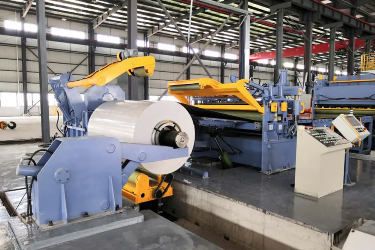
I. Purpose of the automatic sheet uncoiling and leveling line
In the field of sheet metal, with the advancement of science and technology and the rapid development of productivity, the use of coil materials has made significant progress compared to sheet materials. This is because in terms of material turnover, coil materials make dry packaging and transportation from steel mills to users, reducing deformation and loss; in terms of usage, because users can prepare materials on-site according to the needs of the products, and can maximize the use of coil materials for production, greatly improving the utilization rate of materials and enhancing the economic benefits of users.
All these changes stem from the development and improvement of the automatic sheet uncoiling production line. In the past twenty years, the technical level of the sheet uncoiling automatic production line has improved with the continuous increase in product process requirements, its variety and wide applicability, allowing end-users to fully realize the performance-price ratio after selecting this type of production line.
The sheet uncoiling automatic production line can process wide coils longitudinally or transversely into narrow coils or single sheets of required size, and then send them to the stamping production line or flexible sheet processing system within the factory, such as in industries like motors and electrical appliances. There are also some large stamping part manufacturers that have established sheet uncoiling leveling stamping automatic lines with large mechanical presses, punching out complex-shaped blanks, and then sending them to the stamping forming production line to process finished products, such as car door production lines in the automotive industry, and the outer shell production lines of refrigerators, etc.
Additionally, the use of various carbon steels, low alloy steels, non-ferrous metals coils, and colored, coated coils is increasing. The specification range of coils is also gradually expanding, currently with thicknesses from 0.1~25mm, widths from 100~2500mm, and weights up to 40t. The line speed of the uncoiling line transverse cutting production line has reached 80m/min (stop cutting state), 120m/min (flying shear state); the line speed of the uncoiling line longitudinal cutting production line has reached 200m/min.
These coils can all be reprocessed on the sheet uncoiling leveling automatic line, so this type of automatic line has been widely used in industries that use a large amount of sheet materials such as automotive, agricultural machinery, motors, electrical appliances, instruments, light industry, household appliances, building materials, etc.
II. Types and technical parameters of the sheet uncoiling leveling automatic line
The sheet uncoiling leveling automatic line consists of many individual machines, conveying devices, storage devices, etc., connected together. Each device on the line meets the production requirements of the entire line, with reasonable process configuration.
Generally, the sheet uncoiling leveling automatic line should include the following equipment and devices: such as loading car, uncoiler, feeding device, leveling unit, shearing equipment, punching equipment, bridge changer, lead-in mechanism, recoiler, stacking mechanism, etc., depending on the specific line’s process purpose and the needs of the processed blanks. Common types of sheet uncoiling leveling automatic lines are as follows:
1. Sheet metal uncoiling leveling longitudinal shearing automatic line
Sheet metal uncoiling leveling longitudinal shearing automatic line as shown in Figure 1.
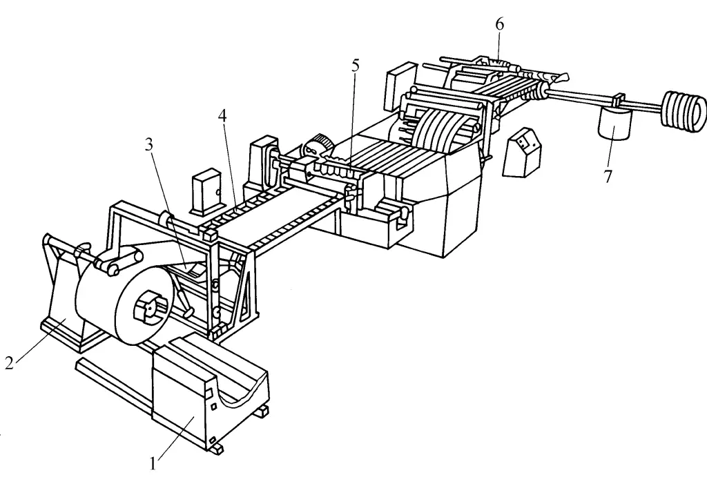
1—Loading trolley
2—Uncoiler
3—Leveling device
4—Material rack
5—Multi-strip shearing machine
6—Rewinder
7—Coil rack
Place the wide coil material purchased by the steel rolling mill into the loading cart 1, start it and stop at the appropriate position of the uncoiler 2, the hydraulic cylinder piston lifts the coil material so that the center of the inner hole of the coil material coincides with the center of the drum of the uncoiler, start the loading cart so that the drum of the uncoiler enters the inner hole of the coil material, the coil expands, tightens the coil material and supports the weight, the hydraulic cylinder piston retracts, the loading cart leaves the uncoiler and stops in place, and loads another coil material for next use.
The coil material on the uncoiler is pressed by the pressing roller, the coil is loosened and the material head is processed to enter the feed roller, it is leveled by the multi-roller plate leveling device 3, passes through the material rack 4, feed roller, and enters the multi-strip shear machine 5, adjust the distance between adjacent disc blades and the gap and overlap between the upper and lower disc blades according to the required strip width, then the required strips can be sheared. After passing through the separation device, it enters the recoiler 6 through the tensioning device, thus converting the wider coil material into several strips of the same or different widths, for use on various press production lines.
See Table 1 for the technical parameters of the automatic line for uncoiling, leveling, and longitudinal shearing of plates.
Table 1 Technical parameters of the automatic line for uncoiling, leveling, and longitudinal shearing of plates (produced by Jinan Foundry and Forging Jiemai Forging Press Company)
| Parameters | Shear plate thickness/mm | Shear plate width/mm | Number of shear strips/(strips) | Coil material weight/t |
| 0.5×800 | 0.05~0.5 | 300~800 | 10~40 | 4 |
| 1.5×1000 | 0.2~1.5 | 600~1000 | 10~40 | 5 |
| 2×1250 | 0.3~2 | 600~1250 | 10~30 | 10 |
| 3×1600 | 0.4~3 | 1000~1600 | 8~20 | 10 |
| 4×1600 | 0.5~4 | 1000~1600 | 8~20 | 10 |
| 6×1600 | 1~6 | 1000~1600 | 6~20 | 15 |
| 10×1600 | 3~10 | 1000~1600 | 3 ~10 | 20 |
2. Sheet metal uncoiling leveling transverse shearing automatic line
Sheet metal uncoiling leveling transverse shearing automatic line as shown in Figure 2.
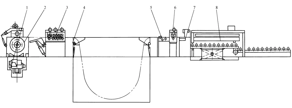
1 – Loading cart
2 – Uncoiler
3 – Roll plate leveling machine
4 – Swing bridge
5 – Deviation correction mechanism
6 – Feeding mechanism
7 – Shearing machine
8 – Stacking mechanism
The coil material is fed into the uncoiler 2 by the feeding trolley 1, the coil is expanded and after the pressure roller is tightened, it loosens, the plate enters the multi-roll plate leveling machine 3, after leveling it passes through the swing bridge 4, storage pit, the deviation correction mechanism 5 adjusts the feeding center, then enters the feeding mechanism 6, and is fed into the shearing machine 7 (or flying shear), the control system issues a shearing signal, which can then shear into single sheets of the required length, and then enters the stacking mechanism 8 for bundling, or is sent to the stamping line for use.
See Table 2 for the technical parameters of the transverse shearing automatic production line for uncoiling and leveling of plates.
Table 2 Technical parameters of the transverse shearing automatic production line for uncoiling and leveling of plates (produced by Jinan Foundry and Forging Jiemai Forging Company)
| Parameters | Shearing thickness/mm | Clipboard width/mm | Shearing length/mm | Coil mass/t |
| 0.5×800 | 0.05~0.5 | 200~800 | 200~2500 | 5 |
| 1×1250 | 0.1~1 | 600~1200 | 200~2500 | 5 |
| 2×1250 | 0.3~2 | 1000~1600 | 200~2500 | 10 |
| 3×1600 | 0.5~3 | 1000~1600 | 500~2500 | 10 |
| 6×2000 | 2~6 | 1000~2000 | 200~4000 | 10 |
| 8×1600 | 2~8 | 1000~1600 | 200~2500 | 20 |
| 10×2000 | 3~10 | 1000~2000 | 200~2500 | 25 |
| 12×2000 | 4~12 | 1000~2000 | 200~2500 | 30 |
| 16×2000 | 5~16 | 1000~2000 | 200~2500 | 35 |
| 20×2500 | 8~20 | 1000~2500 | 1000~5000 | 40 |
3. Sheet metal uncoiling, leveling, longitudinal and transverse shearing combination automatic line
In order to fully utilize the production capacity of online equipment, reduce equipment investment and factory floor space, and save energy, some manufacturers have recently equipped sheet metal uncoiling, leveling, longitudinal and transverse shearing combination automatic lines, significantly improving the production efficiency of the equipment on the line, broadening the applicable range of the equipment, and allowing one line to perform the functions of two lines. The Jinan Foundry and Forging Machinery Research Institute has adapted to market needs and timely developed this type of automatic line, with equipment configuration shown in Figure 3.

1 – Loading cart
2 – Uncoiler
3 – Multi-roller plate leveling machine
4 – Swing bridge
5 – Feeding mechanism
6 – Multi-strip shearing machine
7 – Coiler
8 – Discharge cart
9 – Rectifying mechanism
10 – Feeding mechanism
11 – Shearing machine
12 – Stacking mechanism
The coil material is fed from the loading cart 1 into the uncoiler 2, the reel expands and clamps the coil material, then loosens it, and the sheet metal enters the multi-roller plate leveling machine 3, passes through the swing bridge 4, enters the feeding mechanism 5 into the multi-strip shearing machine 6, lifts the material bridge, and after shearing separation, the multi-strip material enters the coiler 7. The reformed multi-disk coils are packaged and sent to the discharge cart 8, thus completing the longitudinal shearing process.
If the upper cutter shaft of the multi-strip shearing machine 6 is raised and the material bridge is flattened, then the leveled sheet metal is adjusted by the rectifying mechanism 9 to the center, sent into the feeding mechanism 10, and the shearing machine 11, thus shearing into fixed-length single sheet metal, sent into the stacking mechanism 12, and used directly on the stamping line after packaging, thus completing the transverse shearing process. According to needs, longitudinal shearing, coiling, transverse shearing, and stacking of the coil material can also be performed simultaneously.
4. Sheet metal uncoiling leveling stamping automatic line
There are two types of sheet metal uncoiling leveling stamping automatic lines, one is the blanking type automatic line, and the other is the stamping forming automatic line, as shown in Figure 4.
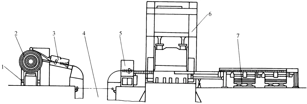
1-Uncoiler
2-Coil
3-Sheet leveling unit
4-Storage pit
5-Feeding unit
6-Mechanical press
7-Stacking device
The coil feeder 2 sends the coil into the uncoiler 1, after loosening, it enters the plate leveling unit 3, after leveling, it passes through the storage pit 4, and the feeding unit 5 sends the plate material into the mechanical press 6 for blanking. The trimmed material is then transported by the conveyor belt to the stacking device 7, and then collectively transported to the next process.
This type of large-scale stamping automatic line is mostly used for blanking, and is widely used in the automotive industry, such as for automatic lines for car doors or other large cover parts to prepare blanks. The stamping forming automatic line only needs to configure the corresponding uncoiling and leveling device in front of the open or closed mechanical press according to the size and shape of the parts, and the parts can be directly produced.
5. Uncoiling and leveling device
The aforementioned types of plate uncoiling and leveling automatic lines are mostly used for the modification of coils, or to prepare blanks for large-scale plate stamping automatic lines. For the modified narrow coils, the uncoiling and leveling device for unfolding treatment before stamping forming is shown in Figure 5.
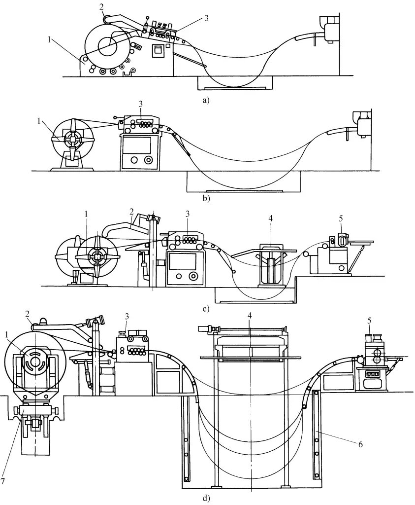
a) Type I
b) Type II
c) Type III
d) Type IV
1 – Uncoiler
2 – Pressure roller
3 – Leveling device
4 – Guiding platform
5 – CNC feeding device
6 – Photoelectric monitoring device
7 – Loading cart
Type I: Cradle type uncoiling leveling device (see Figure 5a). Used for coil thickness 0.6~3.2mm, coil width less than 400mm, maximum coil weight 1500kg.
Type II: Single roll simple uncoiling leveling device (see Figure 5b). Used for coil thickness 0.6~3.2mm, coil width less than 610mm, maximum coil weight 3000kg.
Type II: Double roll simple uncoiling leveling device (see Figure 5c). Used for coil thickness 0.6~4mm, coil width 150~610mm, maximum coil weight 3000kg.
Type M: Heavy-duty uncoiling leveling device (see Figure 5d). Used for coil thickness 0.6~3.2mm, coil width 300~1300mm, maximum coil weight 15000kg.
III. Main Equipment Structural Performance of Sheet Metal Uncoiling and Leveling Automatic Line
Due to the increased productivity requirements, the main processing equipment in the sheet metal uncoiling and leveling automatic line mostly uses specialized equipment, such as uncoilers, shearing machines, leveling machines, slitting machines, and recoilers. These types of equipment are introduced as follows:
1. Uncoiler
The uncoiler is mainly used to support the coil material and unroll the coil material at a set line speed through the transmission system, or with minimal external force. Since the coil material has already undergone elastic-plastic bending deformation when coiled, it will relax due to the rebound effect when uncoiled. To prevent accidents, a pressing roller is usually set on the upper part of the uncoiler, and only after pressing can the coil be loosened.
The structure and type of the uncoiler are distinguished based on different support forms, with different supports suitable for different coil weights and widths. For large-tonnage coil materials, a double-support type is often used, which involves using the cones at the ends of two uncoiler shafts to insert into the inner holes at both ends of the coil material, lifting the coil material, with the disadvantage of causing deformation of the inner ring of the coil material. Another method involves using a fan-shaped plate to tighten the inner hole of the coil material, overcoming the aforementioned disadvantage.
The distance between two uncoilers can be adjusted. For smaller tonnage coil materials, a single-support type is mostly used, where the inner hole of the coil material is fitted onto the mandrel of one uncoiler, and the fan-shaped plate props it up, tightening the coil material. The rotation of the large uncoiler mandrel and the coil material is generally driven by an electric motor through a reduction system, and the opening and closing movement of the fan-shaped plate tightening the inner hole of the coil material is driven by hydraulic or screw pair, and manual operation is also used.
Technical parameters of the uncoiler are shown in Table 3.
Table 3 Technical Parameters of the Uncoiler (Produced by Jinan Foundry and Forging Jiemai Forging Company)
| Parameters | Maximum mass of coil material/kg | Maximum width of coil material/mm | Roll material inner diameter/mm | Roll material maximum outer diameter/mm | Reel opening and closing type | Position adjustment amount/mm |
| E-1-30 | 1000 | 300 | 800 | 1200 | Manual | — |
| E-3-61 | 3000 | 610 | 1200 | Manual | — | |
| EDR-1-30 | 1000×2 | 300 | 1200 | Manual | — | |
| EDR-3-61 | 3000×2 | 610 | 1200 | Manual | — | |
| E-5-61 | 5000 | 610 | 1500 | Hydraulic | — | |
| E-5-100 | 5000 | 1000 | 1500 | Hydraulic | — | |
| E-10-61 | 10000 | 610 | 508 | 1800 | Hydraulic | — |
| E-10-100 | 10000 | 1000 | 1800 | Hydraulic | — | |
| EA-5-61 | 5000 | 610 | 1500 | Hydraulic | 200 | |
| EA-5-100 | 5000 | 1000 | 1500 | Hydraulic | 250 | |
| EA-10-61 | 10000 | 610 | 1800 | Hydraulic | 200 | |
| EA-10-100 | 10000 | 1000 | 1800 | Hydraulic | 250 | |
| EA-15-130 | 15000 | 1300 | 1800 | Hydraulic | 400 |
2. Shearing machine
The shearing machine is an important equipment on the automatic line for uncoiling, leveling, and transverse cutting of sheet metal. The number of cutting strokes of the shearing machine largely determines the production efficiency of the uncoiling line. This is because the uncoiling line has the following special requirements for the shearing machine:
- High productivity;
- Full load;
- High reliability;
- Diversity of coil materials;
- Special cutting methods, etc.
Therefore, ordinary shearing machines can no longer meet the requirements of the uncoiling line, and some special shearing machines are needed. Below, we will focus on introducing several types of products:
(1) Stop-cutting products
In this type of uncoiling line, the strip is cut in a stopped state after the fixed length is fed, which is the so-called “stop-cutting” state using the cutting unit.
1) Dedicated hydraulic transmission shearing machine
The uncoiling lines produced in China initially mostly used hydraulic shearing machines. They come in two structural forms: guillotine and swing beam, where the guillotine type is mainly used for thin sheets (thickness ≤6mm), and the swing beam type is mainly used for thick plates (thickness ≥6mm).
The above products, with their existing productivity, combined with the subsequent material stacking device, can meet the needs of numerous users who do not have high productivity requirements for uncoiling lines. For example, when cutting fixed-length sheets of 2000mm on a 3×1600 uncoiling line, the hydraulic shearing machine can only reach up to 20 sheets/min.
2) Dedicated mechanical transmission shearing machine
The mechanical transmission shearing machine, which uses a combined pneumatic friction clutch, has the greatest advantage of rapid performance, with its idle stroke frequency reaching 80~120min, which is unachievable by hydraulic shearing machines.
Theoretically, its single shearing cycle time is only 0.37~0.75s, and if matched with an appropriate CNC fixed-length feeding mechanism, the productivity can reach 30 sheets/min on a 3mm thick uncoiling line with a fixed length of 2000mm.
This type of shearing machine features a three-point clamping rolling guide rail, which not only eliminates the gap between guide rails, simplifies the lubrication of the guide rails, prevents heating and pulling injuries of the guide rails, but more importantly, allows online adjustment of the blade gap, making it convenient for users.
(2) Flying shear products
The flying shear machine is a shearing machine that can perform transverse fixed-length shearing during the movement of the strip, and its biggest feature is continuous shearing. It can meet the needs of some strips with high surface quality requirements, such as stainless steel, aluminum, galvanized sheet, color coated sheet, etc.
Traditional flying shears are widely used in the continuous rolling mills and continuous finishing lines in the metallurgical industry. However, due to their complex structure and high cost, they are not suitable for use in the aforementioned uncoiling lines.
Until the end of the last century, the emergence of new flying shears largely solved these problems. The new flying shears have been rapidly developed abroad. Some domestic uncoiling line manufacturers are also developing and researching them. Below, the rotary flying shear is introduced.
The operating speed of this type of uncoiling line can reach 100m/min, or even higher. Its control system also automatically generates numerical commands to drive the flying shear based on the preset fixed length and feed speed, and compares the detected feed speed and length with the commands.
When the feed length is close to the set length, the flying shear accelerates or decelerates, precisely positioning at the cutting location, while the flying shear and the plate material achieve speed synchronization and perform cutting, then the flying shear accelerates or decelerates, and the blade returns to the original position.
Currently, the specifications of flying shear uncoiling lines needed in the domestic market generally do not exceed 3mm, with the strip movement speed within 100m/min, and the maximum number of cuts per minute is within the range of 100 to 120. This means that with a fixed length of 2000mm on a 3mm thick uncoiling line, the productivity can reach 35 to 40 sheets/min, especially suitable for uncoiling line products with fixed lengths ≤500mm. These parameters are acceptable to most users and are also economically appropriate.
3. Multi-roller plate leveling machine
Used to apply alternating loads to bent and deformed plates, causing them to bend multiple times in opposite directions, gradually reducing the yield strength of the material, and the original deformation of the plate gradually decreases or disappears. The working principle of the multi-roller plate leveling machine is shown in Figure 6.
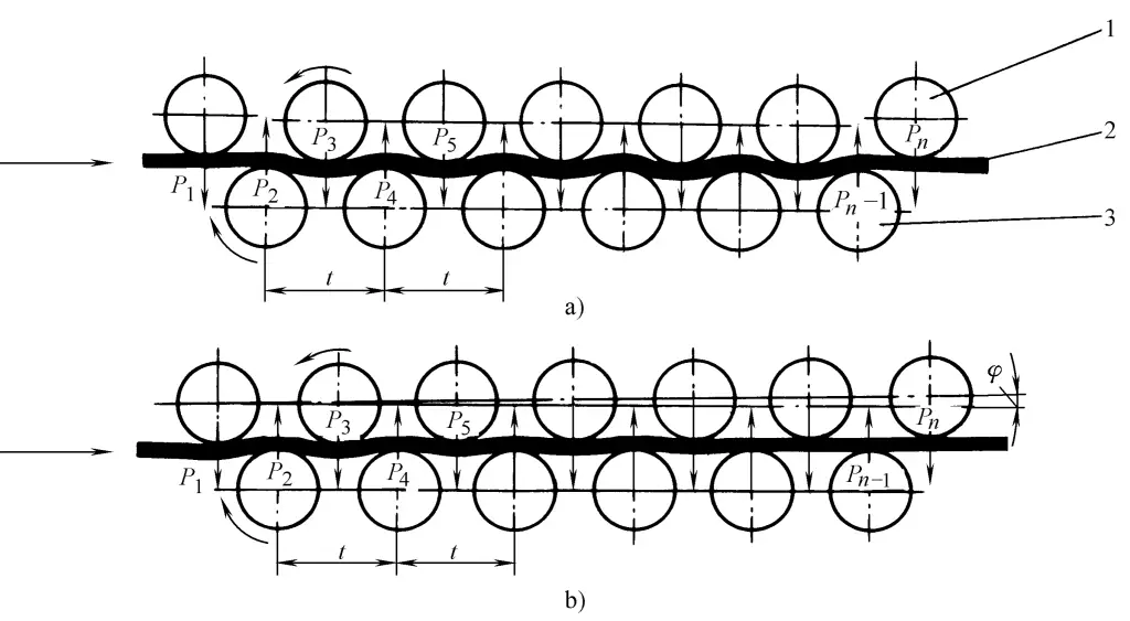
a) The upper and lower work rolls are arranged in parallel
b) The upper and lower work rolls are arranged at an angle
1—Upper work roll
2—Leveling plate material
3—Lower work roll
The multi-roll plate leveling machine consists of upper and lower rows of staggered work rolls, driven by an electric motor through a reducer, gear distribution box, and universal coupling. The upper row of rolls can be adjusted up and down in a parallel arrangement (see Figure 6a), and in addition to up and down adjustments, it can also be tilted at a small angle in the inclined arrangement (see Figure 6b).
Parallel arrangements are mostly used for leveling steel plates thicker than 12mm, while inclined arrangements are mostly used for leveling steel plates thinner than 4mm. The roll spacing and the number of rolls directly affect the leveling quality of the steel plate. If the roll spacing is too large, it reduces the leveling precision; if too small, it increases the pressure on the work roll body (P t to P n ). When leveling the plate material, it is necessary to pre-adjust the amount of pressure exerted by the upper work rolls according to the thickness of the plate to ensure leveling quality.
Technical parameters of multi-roll plate leveling machines produced in China are shown in Table 4.
Table 4 Technical parameters of roller plate leveling machines
| Item | Group 1 | Group 2 | Group 3 | Group 4 | Group 5 | Group 6 | Group 7 | |||
| Number of rolls n | 23 | 23 | 23 | 21 | 17(21) | 17 | 13 | |||
| Roll gap t/mm | 25 | 32 | 40 | 50 | 63 | 80 | 100 | |||
| Roll diameter D/mm | 23 | 30 | 38 | 48 | 60 | 75 | 95 | |||
| Minimum thickness of steel plate hmin (σs ≤392MPa)/mm | 0.2 | 0.3 | 0.4 | 0.5 | 0.8 | 1 | 1.5 | |||
| Effective length of roll body L / min | 1200 | Width of steel plate b / mm | 1000 | 0.6 | 1.2 | 2 | 2.8 | 4 | 5.5 | 8 |
| 1450 | 1250 | 1 | 1.6 | 2.5 | 3.8 | 5 | 10 | |||
| 1700 | 1500 | 0.9 | 1.5 | 2.2 | 3.5 | 4.5 | 9 | |||
| 2000 | 1800 | 1.4 | 2 | 3.2 | 4 | 6 | ||||
| 2300 | 2000 | 2 | 3 | 4 | 6 | |||||
| 2800 | 2500 | |||||||||
| 3500 | 3200 | |||||||||
| 4200 | 4000 | |||||||||
| Maximum straightening speed Vmax /(m/s) | 1 | 1 | 1 | 1 | 1 | 1 | 1 | |||
| Maximum power of the main motor Nmax /kW | 13 | 30 | 55 | 80 | 95(110) | 130 | 155 | |||
| Maximum load characteristic Wx /knm | 0.144 | 0.486 | 0.141 | 3.2 | 7.2 | 12.8 | 28.8 | |||
| Item | Group 8 | Group 9 | Group 10 | Group 11 | Group 12 | Group 13 | Group 14 | |||
| Number of rollers n | 13 | 11 | 11 | 9 | 9 | T | 7 | |||
| Roll gap t/mm | 125 | 160 | 200 | 250 | 300 | 400 | 500 | |||
| Roll diameter D/mm | 120 | 150 | 180 | 220 | 260 | 340 | 420 | |||
| Minimum thickness of steel plate h min (σs ≤392MPa)/mm | 2 | 3 | 4 | 5 | 6 | 10 | 16 | |||
| Effective length of roll body L / min | 1200 | Width of steel plate b / mm | 1000 | |||||||
| 1450 | 1250 | 15 | ||||||||
| 1700 | 1500 | 14 | 19 | |||||||
| 2000 | 1800 | 8 | 13 | 18 | ||||||
| 2300 | 2000 | 8 | 12 | 17 | 25 | 32 | ||||
| 2800 | 2500 | 16 | 22 | 28 | 40 | 50 | ||||
| 3500 | 3200 | 20 | 25 | 36 | 45 | |||||
| 4200 | 4000 | 32 | 40 | |||||||
| Maximum straightening speed Vmax /(m/s) | 0.5 | 0.5 | 0.3 | 0.3 | 0.3 | 0.2 | 0.1 | |||
| Maximum power of main motor Nmax /kW | 130 | 130 | 245 | 180 | 210 | 180 | 110 | |||
| Maximum load characteristic Wx /knm | 51.2 | 115.2 | 256 | 512 | 800 | 1640 | 2560 | |||
4. Multi-strip shear machine
Multi-strip shear machines are often used for cutting wider coil materials into multiple strips of the same or different widths according to user needs, and then rewinding them into coils using a recoiler. They are frequently used in uncoiling, leveling, and slitting lines, and also for trimming the edges of strip materials.
The maximum thickness of the material that this machine can cut is up to 12mm, commonly used are those less than 4mm thick. For some materials with higher strength, the minimum thickness can reach 0.05mm when using tensile shearing, but it is difficult to guarantee the quality of the cut. Generally, 12 pairs of cutter discs can be configured on the upper and lower cutter disc shafts of this machine. For some thin and narrow strips, products from some foreign companies can have up to 42 pairs of cutter discs, capable of cutting 41 narrow strips simultaneously.
On most longitudinal shearing lines using multiple strip shearing machines, due to the structural limitations of auxiliary devices, shearing quality, and ease of adjustment, the number of strips sheared is generally limited to within 20. The maximum width of the sheared strip material is generally less than 2000mm, and the minimum width is related to the thickness of the strip.
The multi-strip shearing machine consists of a machine body 1, a movable cutter disc shaft seat 2, a fixed cutter disc shaft seat 3, and a transmission system 4. The transmission system is connected to the upper and lower cutter disc shafts by an electric motor through a reducer and a universal coupling, and its structural appearance is shown in Figure 7.
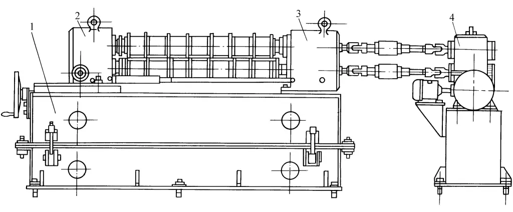
1—Machine body
2—Movable cutter disc shaft seat
3—Fixed cutter disc shaft seat
4—Transmission system
5. Rewinder
The rewinder is used to coil the strip or narrow strip material into rolls. The expansion and contraction of the rewinder drum and the clamping of the jaws are driven by hydraulic and mechanical means.
Hydraulic drive is driven by the piston rod in the hydraulic system, which drives the inclined wedge, causing the reel to expand and the jaws to clamp. It is mainly used for coiling large specifications of wide strip or strip material. Mechanical drive is driven by a screw pair driving a multi-rod mechanism, causing the drum to expand and the jaws to clamp, often used for coiling small specifications of narrow strip or longitudinally cut strip material.
Below is an introduction to the hydraulic drive type coiler (see Figure 8).
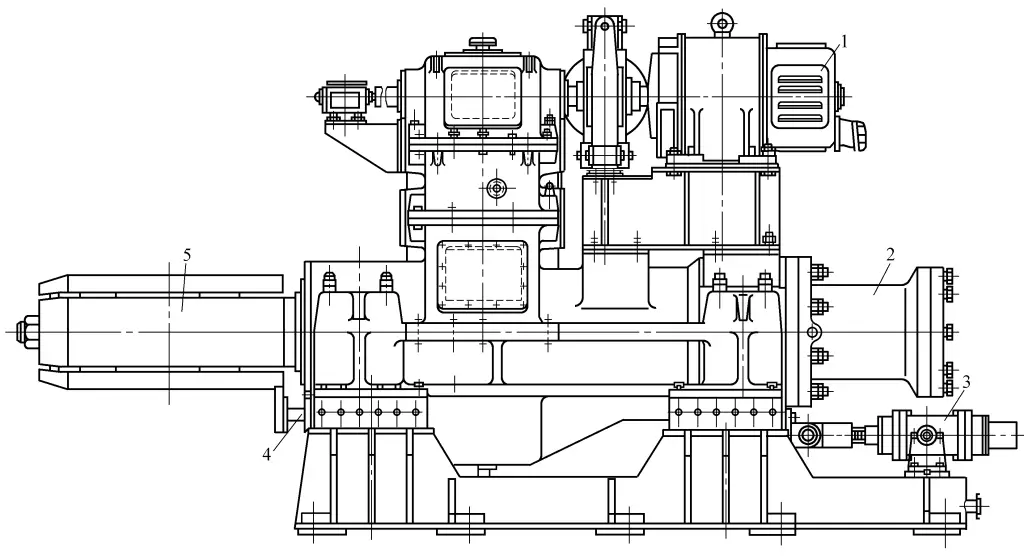
1—Electric motor
2—Axial expansion hydraulic cylinder
3—Coiler floating hydraulic cylinder
4—Belt roll discharge device
5—Reel drum
The electric motor 1 drives the reel drum 5 to rotate through a gear reduction device. It is equipped with an axial expansion hydraulic cylinder 2 for reel expansion and contraction. To ensure the edges of the steel strip are aligned, a floating cylinder 3 is installed on the coiler for deviation control. The coiler also has a hydraulic cylinder push-out device 4 for the belt roll.
Generally, the coiler adopts a single support form with auxiliary support for stable operation. The basic structure of the coiler is similar to that of the uncoiler, but its wedge-shaped slide seat is integral to enhance the rigidity of the reel support.
The winder has four bow-shaped plates on the reel simplifier, which can radially expand and contract by pushing and pulling the inclined wedge with a hydraulic cylinder. When expanded, two of the bow-shaped plates form a pair of clamps used to clamp the head of the slat, and the rotation of the reel completes the winding of the slat.
The winder is driven by an AC motor, with speed controlled by an AC variable frequency speed regulator. A brake is set in the transmission chain. During the winding process, as the coil diameter increases, the control system automatically slows down the winding motor to match the linear speed with the slitting machine.
IV. Introduction to the performance of some auxiliary machines in the automatic leveling line for sheet metal unwinding
Due to the increasing variety and application range of the automatic leveling line for sheet metal unwinding, from the actual usage of users, the performance of some auxiliary machines in the automatic leveling line has played a very important role in the quality of products and the efficiency of the production line. Therefore, it is necessary to introduce some key auxiliary devices to attract the common attention of equipment manufacturers and users.
1. Material opening device
After the coil is loaded into the unwinder, it passes through the lead material press head device, compresses the material head before opening, and lifts during normal operation. The press head can be rotated by a motor, and the material head is first passed through the material opening device, and after the material head is bent and flattened, it enters the leveling machine. Different material opening devices are used for different plate thicknesses or materials.
For thin plates (plate thickness ≤ 6mm), the material opening device consists of a telescopic platform and a lead material platform, both driven by hydraulic cylinders, which can swing up and down and move back and forth.
For thick plates (plate thickness ≥ 6mm), a gantry-type material opening device is generally used. This device consists of a frame, pressure rollers, press head, shovel plate, etc. The press head is located right above the unwinder in the center of the material opening frame, driven by a hydraulic motor to rotate, and moved up and down by a hydraulic cylinder. The slide seat is driven by a push-pull cylinder to move back and forth, the shovel plate is installed on the shovel plate seat and moves with it, and the bottom of the shovel plate is equipped with two lifting hydraulic cylinders, allowing the shovel plate head to move up and down to match the unwinder for even material feeding.
2. Feeding device
The feeding device is crucial in the automatic transverse shearing line for sheet metal leveling, generally ensuring the dimensional accuracy of the sheet material. Figure 9 shows the standard structure schematic of the feeding device.

1—Servo Motor
2—Reducer
3—Shaft Changer
4—Transmission Box
5—Universal Joint
6—Upper Roller
7—Lower Roller
8—Machine Base
The rotation of the feed rollers 6 and 7 is driven by the servo motor 1 through the reducer 2, transmission box 4, and universal joint 5, with adjustable rotation direction and speed. The upper roller 6 can move up and down parallel to the lower roller 7, facilitating the introduction and pressing of the sheet material. The bodies of the upper and lower feed rollers are made of seamless steel tubes welded together, then covered with vulcanized rubber. The hardness requirement is 86 to 88 HS, and the surface roughness is Ra0.8 to 0.4μm.
The upper and lower feed rollers are driven by the same motor, frequently starting and changing between high and low speeds, thus there is a significant inertial impact. To reduce the inertial impact of the upper and lower feed rollers and ensure feeding accuracy, it is necessary to minimize the weight of the feed rollers themselves, ensure high rigidity and strength of the roller shafts, and thus the feed rollers are designed with a hollow structure.
3. Detection Device
The purpose of the detection device is to detect and provide feedback on the feeding accuracy of the sheet material. Figure 10 shows the standard structure schematic of the detection device.
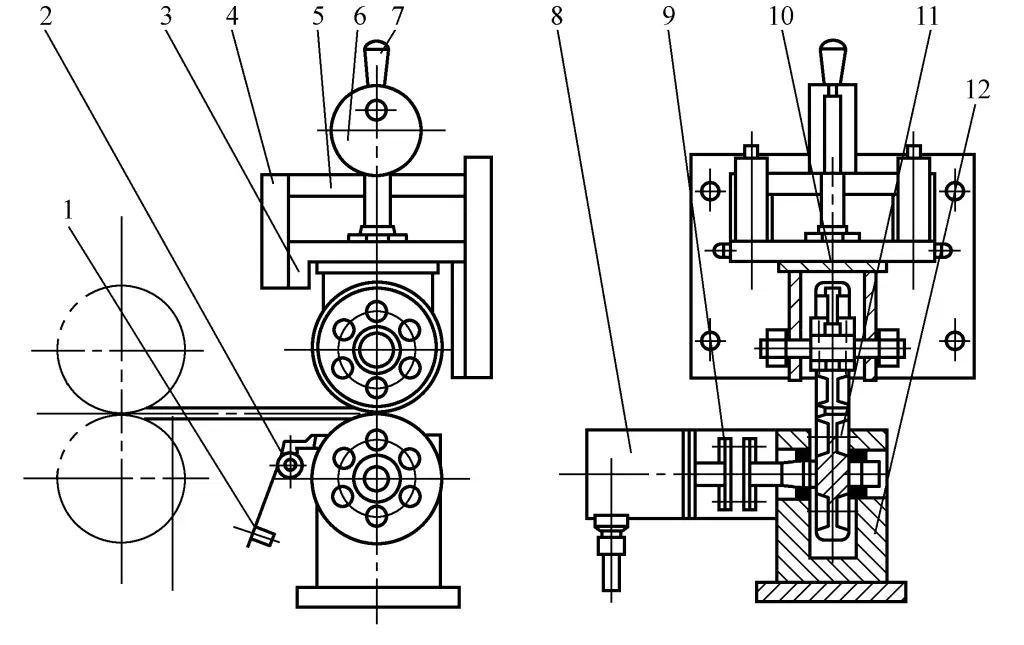
1—Pendulum Weight
2—Scraper
3—Slide Seat
4—Guide Column
5—Fixed Bracket
6—Eccentric Wheel
7—Handle
8—Rotary Encoder
9—Coupling
10—Upper Detection Wheel
11—Lower Detection Wheel
12—Lower Bracket
During operation, first pull the handle 7, using the eccentric wheel 6 to lift the slide seat 3 and the upper detection wheel 10. When the feed roller sends the sheet metal between the upper detection wheel 10 and the lower detection wheel 11, pull back the handle 7, allowing the slide seat 3 and the upper detection wheel 10 to drop. Under the action of spring force, the upper and lower detection wheels clamp the sheet metal tightly.
As the feed roller continues to feed the sheet metal, the sheet metal will drive the two detection wheels to rotate. The rotary encoder 8 is connected to the lower detection wheel through the coupling 9. At this time, the rotary encoder will also rotate synchronously, generating pulses. The detection mechanism is a key component of the feeding section, and its design and manufacturing precision will directly affect the feeding accuracy of the production line, so the design, manufacturing, and installation adjustments of the detection mechanism are particularly important.
The outer circumference of the upper detection wheel is covered with hard rubber to prevent relative sliding between the detection wheel and the surface of the sheet metal during length measurement, reducing measurement accuracy. The lower detection wheel is a rigid integral wheel axle component, reducing assembly errors. Its surface is plated with hard chrome, with a surface hardness of 800~900HV, ensuring long-term operation without wear.
To ensure the accurate operation of the detection wheels, it is necessary to keep the wheel surface clean. The installed scraper 2 is pressed tightly against the wheel surface by adjusting the position of the heavy hammer 1, to remove all adherents on the wheel surface, ensuring measurement accuracy.
4. Bead stacking device
The stacking device mainly satisfies the stacking and alignment of sheet materials after shearing and slitting (the production line has both longitudinal and transverse shearing capabilities), especially for sheet materials that require higher surface precision, this is a particularly difficult problem to solve. The difficulty lies in:
- Aligning the slit sheet materials by width;
- Not allowing scratches on the surface of the sheet materials during the stacking process.
Different stacking devices are used according to different requirements. The following are introduced respectively:
(1) Ordinary conveyor-type bead stacking device
After slitting, the strips are conveyed out along the feed belt, then using their own weight and the inertia generated by the conveyor speed, they slide over the surface of the previous sheet to align, during which an air cushion device is used to minimize scratches between sheets (see Figure 11).

(2) Pneumatic flipping stacking device
Pneumatic material dropping generally consists of a pneumatic support frame, side guards, and rear guards. The stacking adjustment range: width from 100 to 2500mm, length from 100 to 6000mm. In actual production line use, one or more stacking devices may be configured online simultaneously (see Figure 12) to meet the needs of production rate.

Its working principle is: at the end of transverse shearing, the sheet metal is transported to the pneumatic drop-off rack by the conveyor belt. Once in position, a switch signal triggers the rack to flip, and the sheet metal falls flat into a bin formed by two side baffles and a rear baffle. The position of the side baffles is adjustable. It can solve the stacking problem of the entire sheet after transverse shearing, but its disadvantage is that it cannot solve the stacking problem of sheets that have been divided into several strips.
(3) Suction Cup Structure Stacking Device
The suction cup structure is used to handle the sheet metal after shearing and slitting. The main issues it introduces are either a forced slowdown in production pace or excessive production costs.
(4) Electromagnetic Roller Conveyor Belt Slitting Stacking Device
It mainly uses a belt underneath for hanging material transfer, supplemented by a separation belt and a puncher to solve the stacking problem after production line slitting. Its main feature is that it has an electromagnetic roller device installed in the conveyor belt frame that can control the suction force, allowing the slit materials to hang beneath the belt and drop parallel when the power is cut off at the designated position, thus solving the challenge of slitting while ensuring the surface of the workpiece is not scratched.
V. Application Prospects of Sheet Metal Uncoiling and Leveling Automatic Line
1. Specialized uncoiling and drop-off production line in the automobile manufacturing industry
In the late 1990s, the modern automobile manufacturing industry rapidly developed in China. Manufacturers of mid-to-high-end cars with annual outputs greater than 100,000 units turned their attention to investing in uncoiling and drop-off production lines after completing the construction of cold stamping production lines.
The reason is that the sheet metal provided by steel mills has the following disadvantages:
- Poor surface quality, unable to meet the high standards required for exterior coverings;
- Low material utilization rate, limiting the reduction in sedan costs.
This type of production line should meet the supply of the following materials: uncoated cold-rolled sheets, single and double-sided electrolytic plating sheets, single and double-sided hot-dip galvanized sheets, high-strength cold-rolled sheets, high-strength galvanized sheets, hot-rolled pickled sheets, aluminum sheets.
2. Uncoiling and leveling automatic production line for cold bending of various types of materials
Cold-formed profiles are a type of material with development potential for the industrial and construction industries, whose cross-sectional shape can be optimized according to usage needs, designing the most reasonable section, reducing material usage, improving mechanical properties, and enhancing the load-bearing capacity and overall rigidity of components.
Currently, the most commonly used uncoiling and leveling cold bending automatic production line for profiles can complete various forming processes from coil to special-shaped section profiles. Such as: C, Z-shaped steel, car beams, bumpers, shelf profiles, electrical cabinet columns, guardrail plates, etc., meeting the needs of transportation, automotive manufacturing, construction industries, logistics, and thus has a wide development space.
This type of cold bending uncoiling and leveling automatic production line generally consists of an uncoiler, leveler, head cutting welder, feeder, punching machine, cold bending forming machine, flying shear machine, power transmission system, etc.
The coil material passes through the uncoiler, leveler, swing bridge, then enters the punching equipment for punching or cutting, then through the roll forming device, and finally cut to fixed length dimensions by the flying shear machine.

