Understanding Turning Centers for Gear Manufacturing
Imagine a machine that can revolutionize the way gears are produced, combining multiple processes into one seamless operation, and delivering…
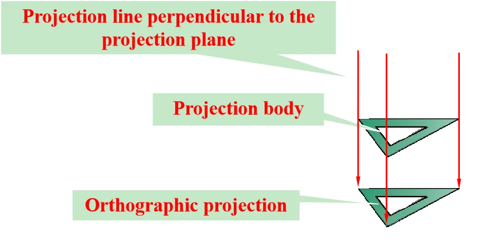
The projection method accurately and completely represents the shape and structure of a form, and is widely used in engineering drawings due to its simplicity and good measurement properties.
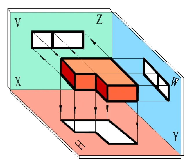
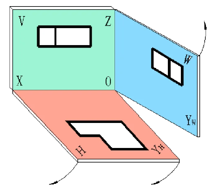
The projection relationship of the three-view drawing: length is represented in the front view, height is represented in the top view, and width is represented in the side view.
In addition to the three basic views (front view, top view, left view), additional views include the right view, bottom view, and rear view.
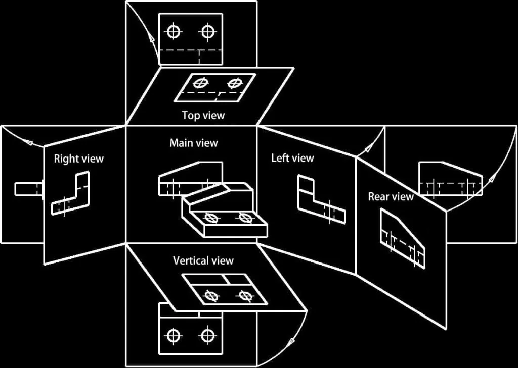
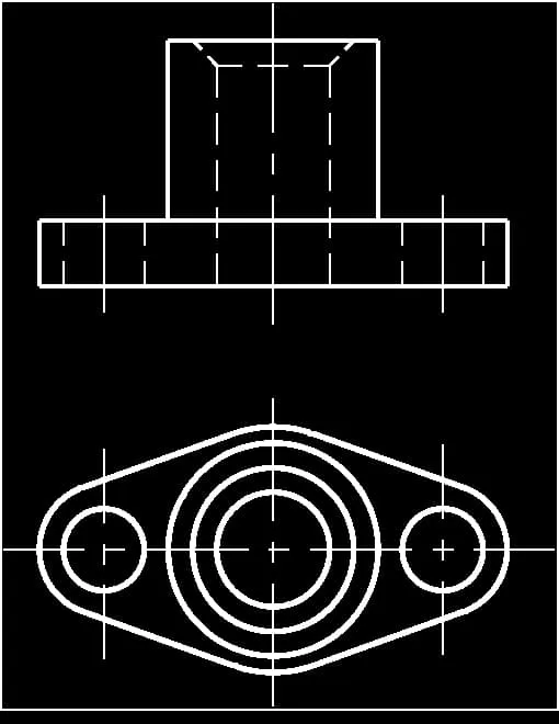
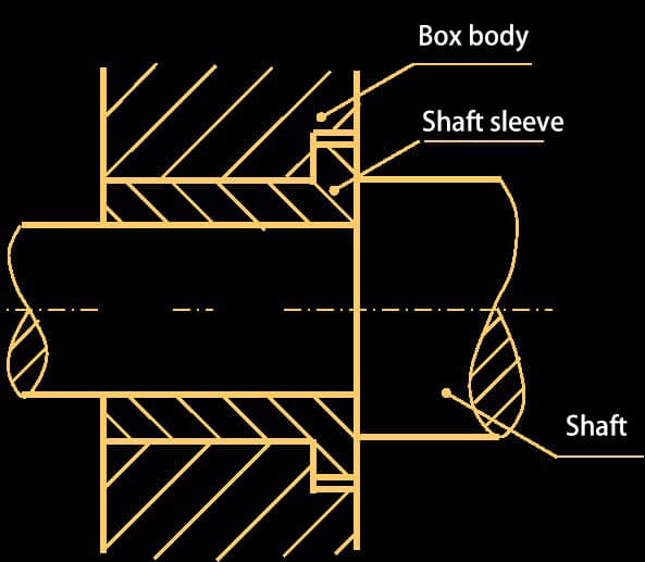
When expressing the internal structure of a machine part using views, the internal structure is represented using dashed lines. The more complex the internal structure’s shape, the more dashed lines will appear in the view, which can affect the clarity of the drawing and make it inconvenient for viewing and dimensioning.
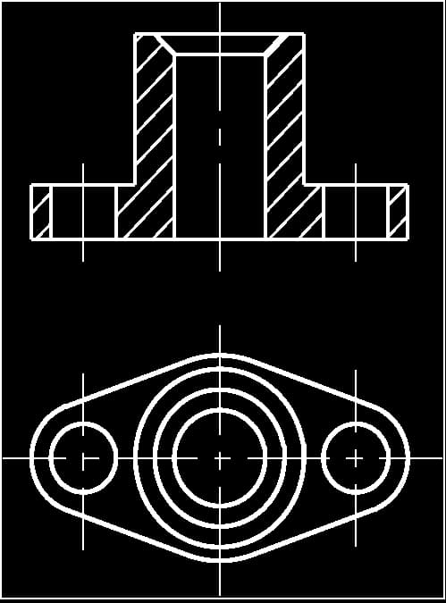
To reduce the number of dashed lines in the view and ensure clarity, the sectional view method can be used to represent the internal structure and shape of the machine part.
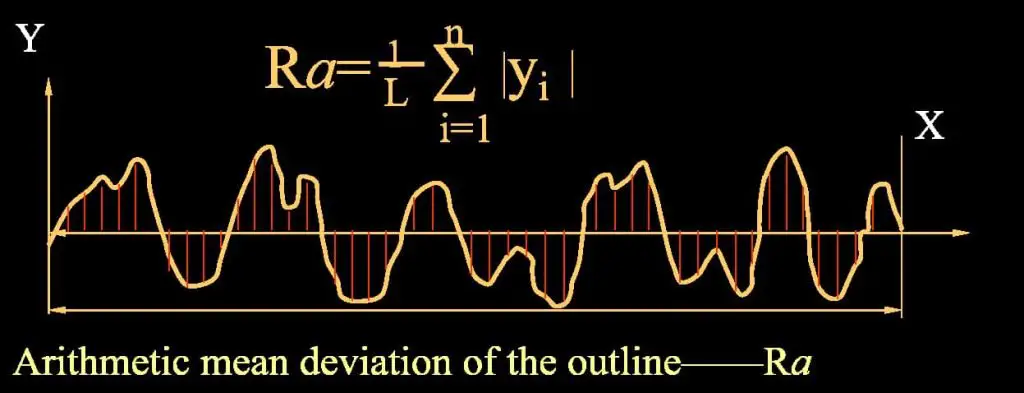
Surface roughness refers to the micro-geometric shape errors formed by small spacing and peaks and valleys on the machined surface of a part.
The primary parameter for evaluating surface roughness is the profile arithmetic mean deviation, Ra.
Surface roughness symbol
| symbol | Meaning and Description: |
 | Surface obtained by any method (used alone, meaningless) |
 | Surface obtained by material removal methods |
 | Surface obtained by non-material removal methods |
| Horizontal line used to indicate relevant parameters and descriptions | |
| Indicates that all surfaces have the same surface roughness requirement |
Surface Roughness Notation Example:
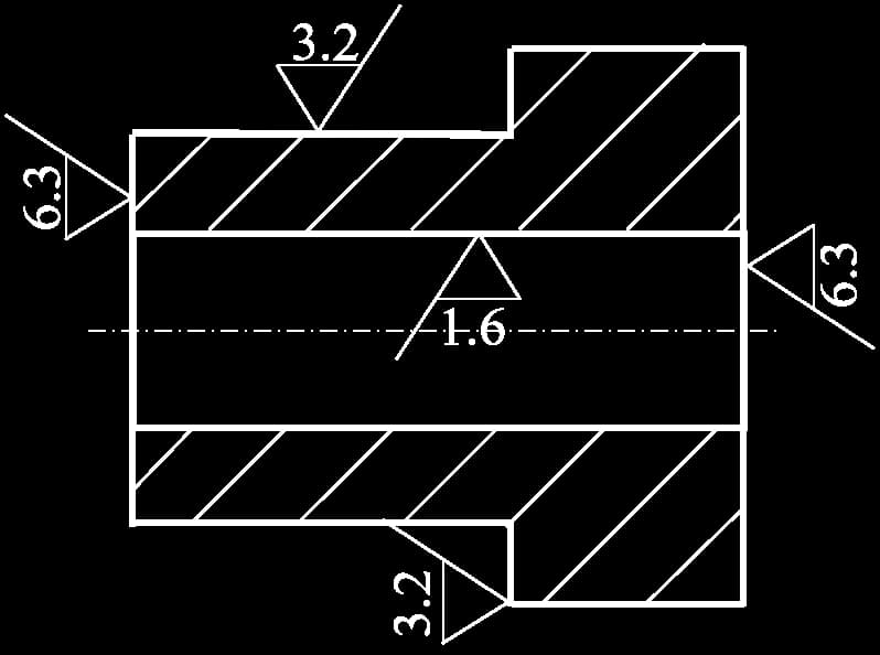
When most surfaces of a part have the same roughness requirement, the symbol for the most commonly used one can be uniformly noted in the upper right corner of the drawing, along with the addition of the word “others.”
For example:
The unit of the surface roughness parameter is μm.
Condition for part acceptance: Maximum limit dimension > actual dimension > minimum limit dimension.
Example:
Condition for part acceptance: Φ50.008 ≥ actual dimension ≥ Φ49.992.
Upper deviation = Maximum limit dimension – Basic dimension
Lower deviation = Minimum limit dimension – Basic dimension
Dimensional tolerance (referred to as tolerance): Permissible variation in actual dimensions.
Tolerance = Maximum limit dimension – Minimum limit dimension= Upper deviation – Lower deviation
Example: Φ50±0.008
Upper deviation = 50.008 – 50 = +0.008 (deviation can be positive or negative)
Lower deviation = 49.992 – 50 = -0.008
Tolerance = 0.008 – (-0.008) = 0.016 (tolerance is always positive)
(1) Concept of fits: The relationship between the tolerance zone of the holes and shafts with the same basic dimensions.
Clearance or interference: δ = actual size of the hole – actual size of the shaft,δ ≥ 0 clearance,δ ≤ 0 interference
(2) Types of fits: Clearance fit, Interference fit, Transition fit
(3) Basis of fits:
① Fundamental hole system: The basic deviation symbol for the basic hole is “H”.
② Fundamental shaft system: The basic deviation symbol for the basic shaft is “h”.
The fit notation is:
Basic size Basic deviation symbol for hole, tolerance grade / Basic deviation symbol for shaft, tolerance grade
For example:
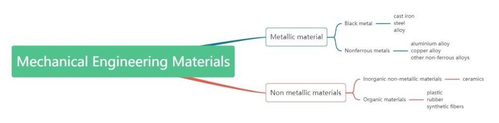
Artificially added with Cr, Mn, Ni, Ti, Mo, etc., possessing high strength, toughness, hardness, and certain special properties (such as corrosion resistance, high-temperature strength, etc.).
Exhibits good casting performance, friction reduction, vibration absorption, machinability, low notch sensitivity, simple production process, and low cost.
1. Heat treatment definition:
Heating, insulation, cooling → changing the overall or surface structure of metal to obtain desired properties.
2. Types of heat treatment:
3. Other heat treatments
Purpose: reduce hardness, refine grain, eliminate internal stress
Purpose: similar to annealing, with higher mechanical performance
Purpose: increase part hardness and wear resistance, strengthen material. However, internal stress occurs after quenching, making the material brittle, requiring tempering.
Purpose: Achieve the hardness required by the design drawings, eliminate internal stress.
Types of tempering processes:
Purpose: Improve the surface hardness and wear resistance of the part.
Purpose: Improve the surface wear resistance, corrosion resistance, oxidation resistance, and fatigue strength of the steel part.
1. Electrolytic Plate: (also known as galvanized plate) SECC (N) (fingerprint resistant plate), SECC (P), DX1, DX2, SECD (stretching plate).
Material hardness: HRB50°±5°, stretching plate: HRB32°~37°.
2. Cold-rolled Plate: SPCC, SPCD (stretching plate), 08F, 20, 25, Q235-A, CRS. Material hardness: HRB50°±5°, stretching plate: HRB32°~37°.
3. Aluminum Plate: AL, AL (1035), AL (6063), AL (5052), and so on.
4.Hot-rolled Plate: Q435, Q436, QSPH75, ZJ330B, ZJ400, Q195, Q215, Q235B, Q226, 08KP, 08YU, HJ41, HP295, etc.
5. Stainless Steel Plate: SUS, SUS301, 2Cr13, 1Cr18Ni9Ti, etc.
6. Other commonly used materials include: pure copper plate (T1, T2), hot-rolled plate, spring steel plate, aluminum-zinc plated sheet, aluminum profiles, etc.
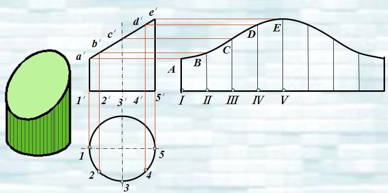
The process of sequentially and continuously flattening a three-dimensional surface onto a plane according to its actual shape and size is referred to as the unfolding of a three-dimensional surface. The resulting diagram obtained after unfolding is called a surface unfolding diagram.
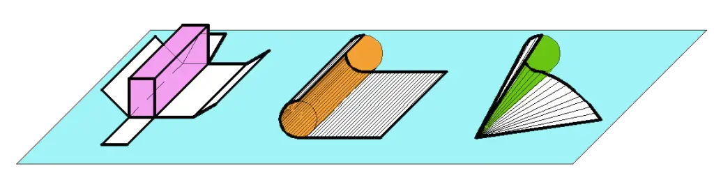
The three-dimensional surface is divided into developable surfaces (the surfaces of planar solids;cylindrical and conical surfaces in curved solids) and non-developable surfaces (such as spherical and helical surfaces).
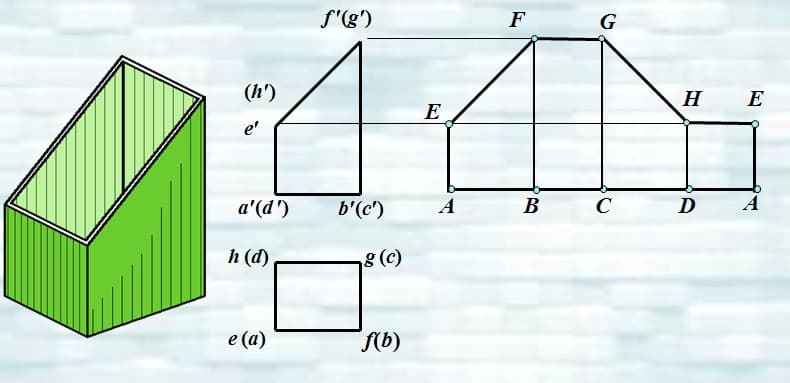
Example: Unfolding of a Prism’s Surface
Example: Unfolding of an Oblique Circular Cylinder Surface
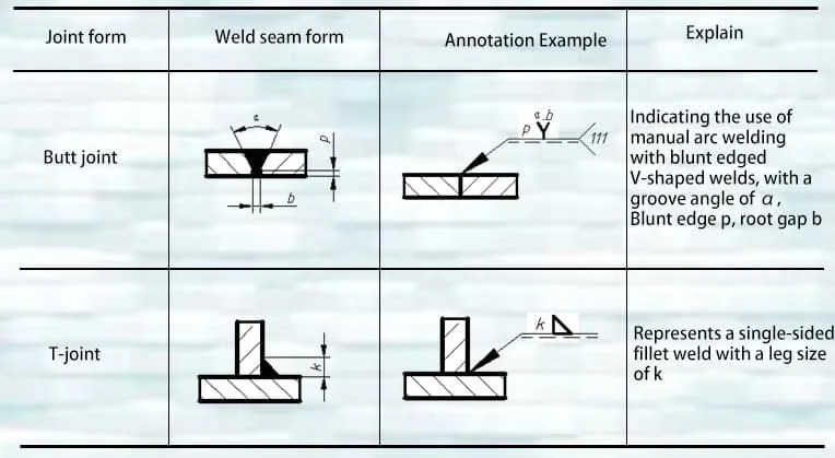
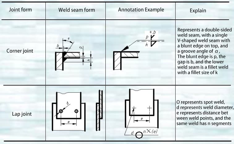
Common Welded Joints:
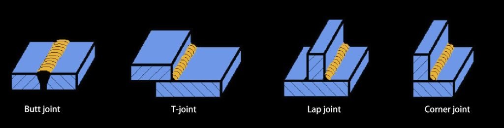
A welding diagram is a pattern used for welding processes. In addition to clearly expressing the structure of the welded workpiece, it should also clearly indicate the position of the weld, the form of the joint, and its dimensions.
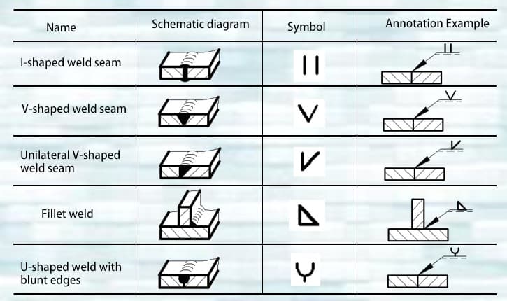
The weld on the pattern can be represented using technical drawing methods. In order to simplify the weld on the pattern, weld symbols and numerical codes for welding methods are generally used for representation.
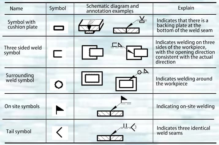
Common basic symbols for welds and examples of their annotations.
Supplementary symbols and examples of their annotations.
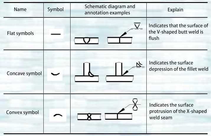
Supplementary symbols and examples of their annotations.
Example of Welding Symbol Notation (1)
Example of Welding Symbol Notation (2)
In comparison with manual forming, the most significant advantage of sheet metal mechanical forming is its high processing accuracy, high degree of automation, and very high production efficiency.
Material cutting involves cutting the material into the required shapes based on unfolding. There are various methods for material cutting, which can be categorized into shearing, punching, and laser cutting based on the type of machine tool and working principle.
1. Shearing: This method involves cutting out the required shapes using a shearing machine or shear. The precision can reach 0.2mm or more, primarily used for cutting strips or cleaning materials.
2. Punching: Material cutting is carried out using a numerical control punching machine (NC) or a conventional punch press. Both methods can achieve a precision of 0.1mm or more. However, the former may leave knife marks during cutting and has relatively lower efficiency, while the latter has high efficiency but entails high initial costs, suitable for large-scale production.
2.1 In CNC punch presses, the upper and lower dies are fixed, and the worktable moves to punch and cut the sheet metal, producing the required workpiece shape.
2.2 In a conventional punch press, the movement of the upper and lower dies, using a blanking die, punches out the required shape of the workpiece. Generally, a conventional punch press needs to be used in conjunction with a shearing machine to punch out the required shape. This means that the strip material is first cut by the shearing machine and then the punch press is used to punch out the required shape of the workpiece.
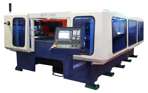
3. Laser cutting – Using laser cutting equipment to continuously cut the sheet metal and obtain the required workpiece shape. Its characteristics include high precision and the ability to process workpieces with very complex shapes, but the processing cost is relatively high.
Machine forming mainly includes bending forming and stamping forming.
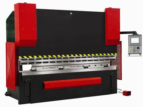
1. Bending forming – The bending machine fixes the upper and lower dies on the upper and lower worktables of the bending machine, and uses a servo motor to drive the relative movement of the worktable. Combined with the shapes of the upper and lower dies, this achieves the bending forming of the sheet metal. The forming accuracy of bending can reach 0.1mm.
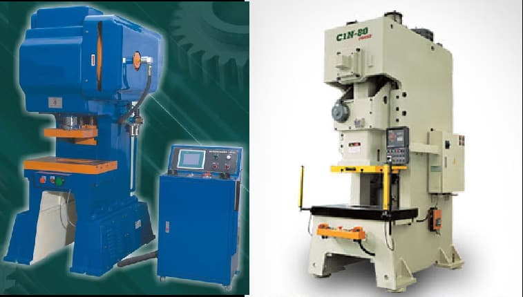
2. Stamping forming – The press uses the power generated by the motor-driven flywheel to drive the upper die. By combining the relative shapes of the upper and lower dies, the sheet metal deforms, achieving the processing and forming of the workpiece. The forming accuracy of stamping can reach above 0.1mm. The press can be divided into conventional presses and high-speed presses.
Welding Characteristics: Sheet metal is mainly composed of steel plates or profiles, and commonly used welding methods include CO2 shielded welding and manual arc welding. Welding has the advantages of saving steel, simple operation, and good sealing performance.
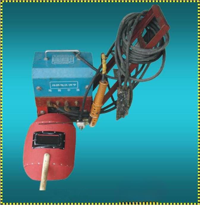
Manual arc welding is a method of using manual operation to manipulate welding rods and weld the workpiece using an electric arc. As the arc moves, a new molten pool is continuously generated, and the molten metal in the original pool continuously cools and solidifies to form a weld, thereby joining the two parts of the workpiece into a whole. The arc welding machine is shown in Figure 4-1.
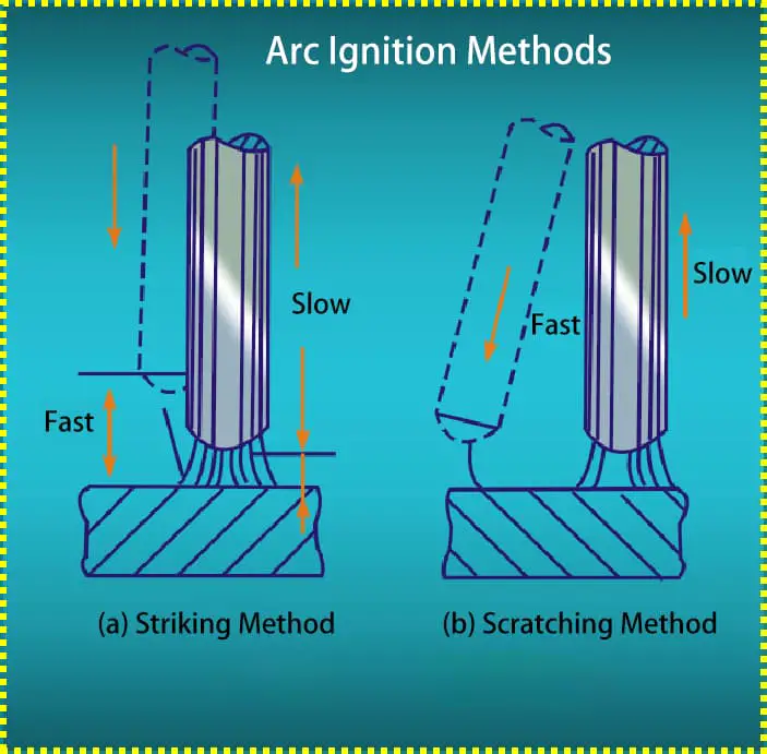
(1) Striking Method:
The striking method involves vertically touching the welding rod to the workpiece, then quickly lifting the welding rod and maintaining a distance of about 3-4mm from the workpiece to generate an electric arc. This method is mostly used in narrow or scratch-sensitive areas of the workpiece, as shown in Figure 4-2a.
(2) Scratching Method:
Lightly scratch the welding rod on the workpiece (approximately 20mm in length), then maintain a distance of about 3-4mm from the workpiece to generate an electric arc, as shown in Figure 4-2b.
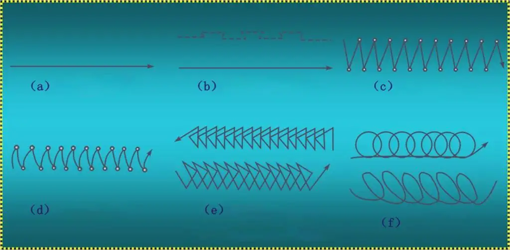
(1) Straight-line Travel Method:
The straight-line travel method involves no lateral oscillation and is suitable for butt welding without beveling for plate thicknesses of 3-5mm, as well as the first layer of multi-layer welding and multi-pass welding, as shown in Figure 4-3a.
(2) Straight-line Back-and-Forth Travel Method:
The straight-line back-and-forth travel method involves the end of the welding rod making a back-and-forth linear oscillation along the weld seam, as shown in Figure 4-3b.
(3) Zigzag Travel Method:
The zigzag travel method involves the end of the welding rod making a continuous zigzag forward movement and pausing briefly at the turning points on both sides, as shown in Figure 4-3c.
(4) Crescent-shaped Travel Method:
The crescent-shaped travel method involves the end of the welding rod making a continuous left-right crescent-shaped forward movement and pausing briefly at the turning points on both sides, as shown in Figure 4-3d.
(5) Triangular Travel Method:
The triangular travel method is divided into the straight triangular travel method and the slanted triangular travel method, as shown in Figure 4-3e.
(6) Circular Travel Method:
The circular travel method is divided into the straight circular travel method and the slanted circular travel method, as shown in Figure 4-3f.
(1) Flat Welding:
Flat welding can be divided into flat butt welding and flat fillet welding.
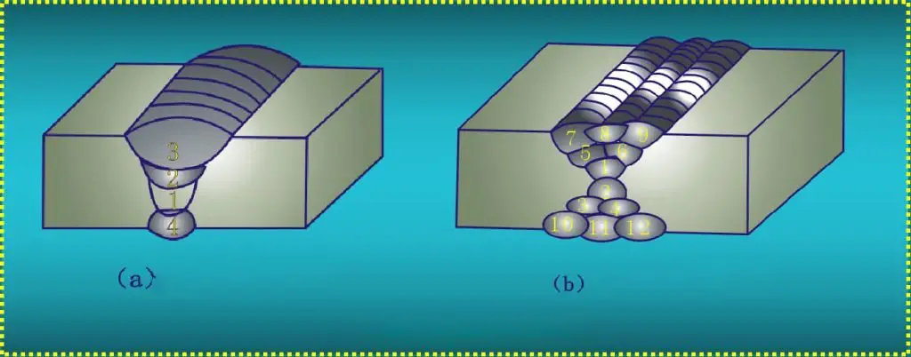
When the thickness of the workpiece is less than 6mm, non-groove flat butt welding is usually used. It is advisable to use a diameter of $3~φ4mm welding rod for short arc welding, ensuring that the depth of the weld pool reaches 2/3 of the plate thickness, the weld width reaches 5~8mm, and the welding method is in a straight-line motion.
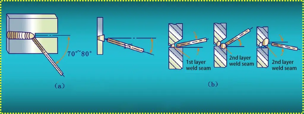
When the thickness of the workpiece is greater than 6mm, groove flat butt welding should be employed, divided into multi-layer welding or multi-pass welding, as shown in Figure 4-4.
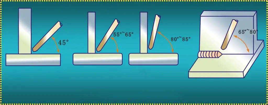
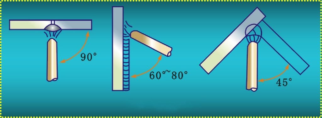
Fillet welding mainly refers to the welding of T-joints and lap joints. These two welding methods are similar. Fillet welding typically uses 3~5mm welding rods, with the welding rod angle as shown in Figure 4-5.
(2) Vertical Welding:
The weld pool in vertical welding is located on a vertical surface, and there are two methods of welding: one is welding from bottom to top, and the other is welding from top to bottom. Generally, the former method is used. When performing vertical welding, the angle of the welding rod is as shown in Figure 4-6.
It is advisable to use smaller diameter and higher current for short arc welding, often employing a straight-line reciprocating motion and triangular motion, building up the weld bead step by step.
(3) Horizontal Welding:
When performing horizontal welding, it is advisable to use smaller diameter welding rods and lower welding currents, employing the short arc method and suitable motion techniques. When the thickness of the workpiece is less than 5mm, it is possible to weld without a groove, using 3.2mm or 4mm welding rods, as shown in Figure 4-7a.
For thicker workpieces, grooves should be used, and in this case, a multi-layer or multi-pass welding method should be employed, as shown in Figure 4-7b.
(4)Welding in the flat position:
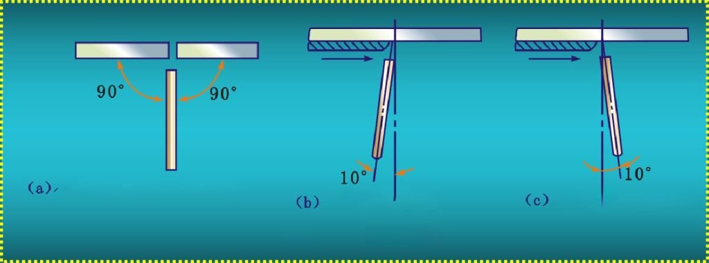
When welding in the flat position, it is important to use the shortest possible arc so that the molten droplets can transition immediately into the weld pool, rapidly merging with the molten metal in the pool, thus promoting rapid solidification of the weld. A smaller diameter welding rod, typically ranging from φ3 to φ4mm, should be selected, and the welding rod angle should be as shown in Figure 4-8.
(1) When sheet metal workers engage in welding work at night, they should use electric lighting. The safe voltage for electric lighting is 36V. In damp environments where the human body’s resistance decreases, the specified voltage for use is 12V. When welding in metal containers or pipelines, a 12V voltage should be used.
(2) Precautions during the welding process:Before welding, wear a face shield, leather gloves, and insulated shoes, and check if the welding equipment and tools are safe.
When welding in narrow spaces, wear insulated shoes, and have two operators alternate work. One person should monitor the operator at all times, and if any signs of danger arise, immediately cut off the power for handling.
Strengthen personal protection. Do not touch high-voltage lines during high-altitude operations, and avoid welding outdoors in rainy weather.
(3) Welding hygiene and protective measures:Ventilation facilities are an effective measure to eliminate the hazards of welding dust and improve working conditions. Their role is to ensure that the air environment in the work area meets hygiene standards, so it is important to ensure that the ventilation facilities are working properly.
When welding inside a workshop, it is necessary to ensure that harmful substances produced during the welding process are promptly discharged and, in principle, undergo purification treatment.
When performing arc welding, a face shield with protective glass must be used. Do not casually change the filter glass, wear a white work suit to reflect intense light.
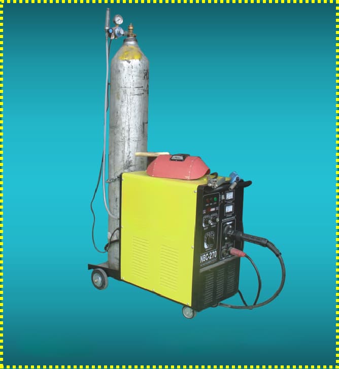
The most commonly used method is the semi-automatic CO2 arc welding machine, as shown in Figure 4-20. The machine automatically feeds the welding wire and delivers CO2 gas, while the welding along the seam is done manually.
It can use welding wires with diameters of 0.6mm to 0.8mm and 1.0mm, suitable for welding workpieces ranging from 0.4mm to 0.8mm in thickness (such as low carbon steel, low alloy steel, stainless steel, etc.) in various positions, including flat, vertical, and overhead, for fillet welding, groove welding, and it can also be used for repairing cast iron.
1. Welding Process Parameters for CO2 Gas Shielded Welding: (Refer to Table 4-1)
| Parameter Name | Selection Criteria | Method Selection |
| Wire Diameter | The wire diameter can be chosen based on the thickness of the workpiece, the position of the weld joint, and productivity requirements. | When welding in the flat position on medium-thick plates, a wire with a diameter of around 1.6mm is suitable. For welding on thin or medium-thick plates in vertical, horizontal, or overhead positions, it is common to use wire with a diameter below 1.6mm. |
| Welding Current | Welding current can be selected based on the workpiece thickness, wire diameter, the position of the weld joint, and the required droplet transfer mode. | When using wire with a diameter of 0.8mm to 1.8mm for short-circuit transition welding, the welding current ranges from 50A to 230A. |
| Arc Voltage | The arc voltage must be appropriately coordinated with the welding current. An increase in arc voltage leads to a corresponding increase in weld width, reinforcement height, and decrease in penetration depth. Conversely, a decrease in arc voltage leads to a reduction in weld width. | During short-circuit transition welding, the arc voltage is within the range of 16V to 25V. When using wire with a diameter of 1.2mm to 3.0mm for coarse droplet transition welding, the arc voltage can be selected within the range of 25V to 44V. |
| Welding Speed | As welding speed increases, the width of the weld, reinforcement height, and penetration depth decrease accordingly; conversely, a decrease in welding speed leads to an increase in these parameters. | The welding speed for semi-automatic welding ranges from 15m/h to 30m/h, while for automatic welding, the welding speed can be slightly faster, generally not exceeding 40m/h. |
| Electrode Extension Length | Electrode extension length refers to the length of the electrode extending from the contact tip during welding. | The length of the wire extension depends on the wire diameter. Generally, a wire extension length of approximately 10 times the wire diameter is suitable. |
| CO2 Gas Flow Rate | The CO2 gas flow rate should be selected based on welding current, welding speed, electrode extension length, and nozzle diameter. | When welding with fine wire using CO2 gas, the CO2 gas flow rate is approximately 5L/min to 15L/min; when welding with thick wire using CO2 gas, the CO2 gas flow rate is approximately 15L/min to 25L/min. |
| Polarity of Power Source | Compared to direct current electrode positive (DCEP), direct current electrode negative (DCEN) offers the characteristics of stable arc, reduced spatter, and greater penetration depth. | To ensure the welding quality of CO2 gas shielded welding, the commonly adopted method is the direct current reverse connection, where the workpiece is connected to the negative pole, and the welding gun is connected to the positive pole. |
| Circuit Inductance | The inductance in the welding circuit should be chosen based on wire diameter, welding current, and arc voltage. | When using Φ0.6mm to Φ1.2mm fine wire, the inductance value is approximately 0.01mH to 0.16mH. When using Φ1.6mm to Φ2mm thick wire, the inductance value is approximately 0.3mH to 0.7mH. |
2. CO2 gas shielded welding operation essentials:
(1) Striking the arc. Due to the low no-load voltage of the arc welding power source and the light welding wire, it is difficult to establish a stable burning point when striking the arc, often resulting in the wire breaking in segments.
(2) Arc extinction. When ending the arc, it is advisable to pause slightly at the crater, then slowly lift the welding gun until the crater is filled, ensuring that the molten metal remains protected by the gas until solidification.
(3) Leftward welding technique. When employing the leftward welding technique, the seam is clearly visible, reducing the likelihood of welding deviation, and allowing for greater penetration, resulting in a more even and aesthetically pleasing weld bead.
(4) Rightward welding technique. When using the rightward welding technique, visibility of the weld pool and the effectiveness of gas protection are improved, though observing the gap of the seam during welding is inconvenient, increasing the risk of welding deviation.
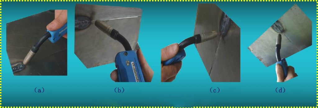
(5) Welding positions. CO2 gas shielded welding encompasses four positions: flat, horizontal, vertical, and overhead, as illustrated in Figure 4-21.
3. Welding Forms:
There are six forms of CO2 gas shielded welding, as shown in Figure 4-22.
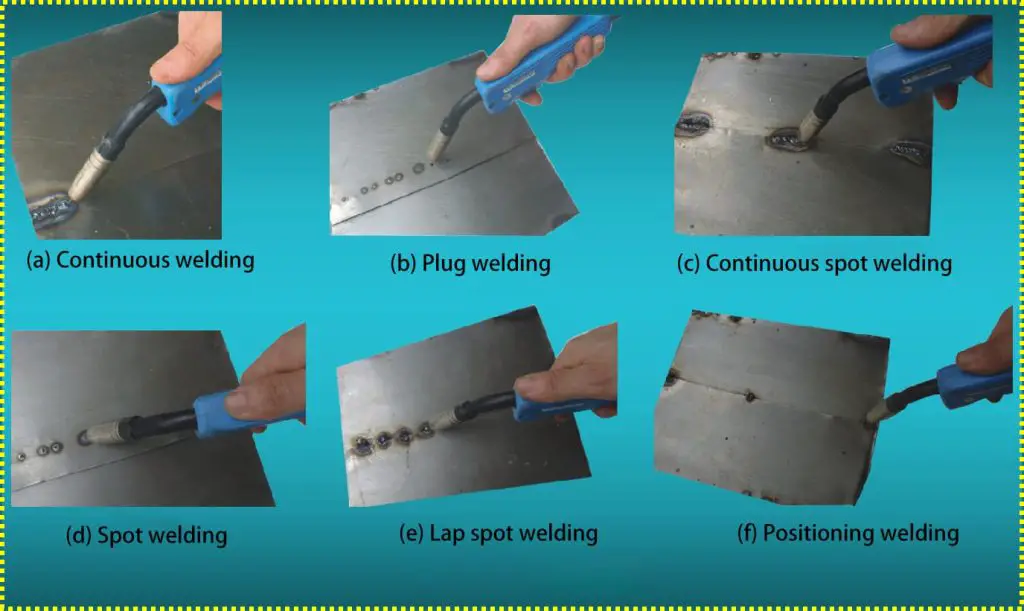
(1) Spot Welding: In fact, it is a temporary spot welding, which is an alternative measure used to keep the relative positions of two welded parts fixed. As shown in Figure 4-23.
(2) Continuous Welding: Refers to the welding form in which the welding gun moves continuously and steadily along the weld to form a continuous weld seam, as shown in Figure 4-24.
(3) Plug Welding: When two metal plates are stacked together and one of the plates has a through-hole, the weld formed by passing the arc through this hole and filling it with molten metal is called plug welding, as shown in Figure 4-25.
(4) Spot Welding: Spot welding is a form of welding in which the arc is introduced into two metal plates being welded when the wire feed timing pulse is triggered, causing a localized melting of the weld.