I. Overview
1. The emergence and development of special processing
Since the 1940s, due to the development of materials science and high technology, fierce market competition, and the urgent need for advanced defense and scientific research, the speed of new product updates has accelerated, developing towards high speed, high precision, high reliability, corrosion resistance, high temperature and pressure, high power, and polarization of size.
As a result, various new materials, new structures, and complex precision mechanical parts have emerged in large numbers, posing a series of urgent problems for the mechanical manufacturing industry to solve.
1) Processing problems of various difficult-to-cut materials, such as hard alloys, titanium alloys, heat-resistant steels, stainless steels, diamonds, gems, quartz, and various high-hardness, high-strength, high-toughness, high-brittleness metal and non-metal materials like germanium and silicon.
2) Processing problems of various special complex surfaces, such as jet turbine blades, integral turbines, engine casings and forging dies, injection molds with three-dimensional forming surfaces, rifling in gun barrels, injectors, grids, and small holes and narrow gaps on spinnerets.
3) Processing problems of various ultra-precision, polished, or special requirement parts, such as aerospace gyroscopes and servo valves with very high surface quality and precision requirements, as well as slender shafts, thin-walled parts, elastic elements, and other low-rigidity parts.
To solve the above series of technological problems, it is difficult or even impossible to rely solely on traditional cutting methods. People have successively explored and researched new processing methods, and special processing emerged and developed under these preconditions. However, the reason why special processing could emerge and develop is that it has essential characteristics that conventional cutting processes do not possess.
The essence and characteristics of conventional cutting processes are: first, relying on tool materials that are harder than the workpiece, and second, using mechanical energy to remove excess material from the workpiece. Generally, this is an effective method, but when workpiece materials become increasingly harder and part structures become more complex, the originally effective method becomes a disadvantageous factor limiting production efficiency and affecting processing quality.
The difference between special processing and conventional cutting processes is that it directly utilizes electrical energy, light energy, sound energy, magnetic energy, thermal energy, chemical energy, or a composite form of several energies for processing. It mainly has the following characteristics:
- Mainly relies on other forms of energy (such as electricity, light, sound, chemistry, etc.) to remove materials.
- The hardness of the tool can be lower than that of the processed material.
- There is no significant mechanical cutting force between the tool and the workpiece during the processing.
2. Classification and comparison of special processing
Special processing is classified according to energy sources and processing principles, as shown in Table 1.
Table 1 Classification of commonly used special processing methods
| Processing method | Energy source | Processing principle | English abbreviation |
| Electrical Discharge Machining | Electrical, thermal energy | Sublimation, melting | EDM |
| Wire Electrical Discharge Machining | Electrical, thermal energy | Sublimation, melting | WEDM |
| Electron Beam Machining | Electrical, thermal energy | Sublimation, melting | EBM |
| Plasma Machining | Electrical, thermal energy | Sublimation, melting | PAM |
| Electrochemical Machining | Electrical, chemical energy | Metal anode dissolution | ECM |
| Electrochemical Grinding | Electrical, chemical energy, mechanical energy | Anode dissolution grinding | EGM |
| Ultrasonic Machining | Sound, mechanical energy | High-frequency abrasive impact | USM |
| Laser Machining | Light, thermal energy | Melting, sublimation | LBM |
| Ion Beam Machining | Electrical energy, kinetic energy | Atomic impact | IM |
| Chemical Etching | Chemical energy | Corrosion | CHM |
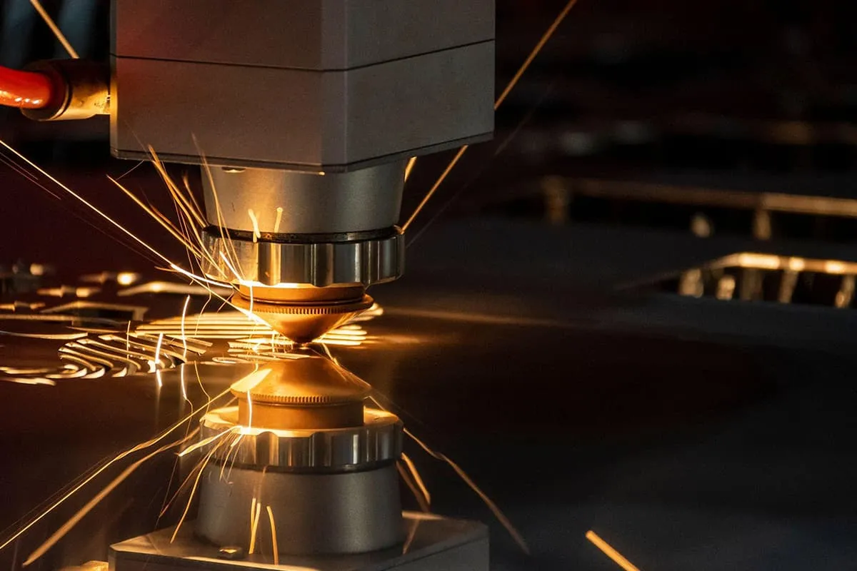
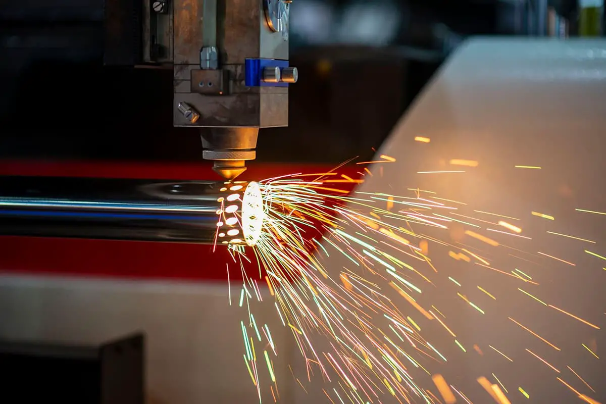
Among these, ion beam machining uses accelerated and focused plasma beams to impact the material surface for processing. Its characteristics are very high processing precision, low pollution, and extremely small processing stress and thermal deformation, but low processing efficiency. Laser machining uses high-power laser beams to irradiate workpieces, causing material melting and sublimation for drilling, cutting, welding, and other special processing.
II. Electrical Discharge Machining Technology
Electrical Discharge Machining (EDM) is a processing technology that uses the electro-erosion effect produced by pulse discharge between the workpiece electrode and tool electrode in a certain liquid medium to erode conductive materials, thereby changing the shape and size of the material.
1. Basic principles, characteristics, and processing range of electrical discharge machining
(1) Basic principles of electrical discharge machining
In an insulating working fluid, the tool and workpiece are connected to the positive and negative poles of a pulse power supply, and a very small discharge gap (usually a few micrometers to a few hundred micrometers) is always maintained, as shown in Figure 1.
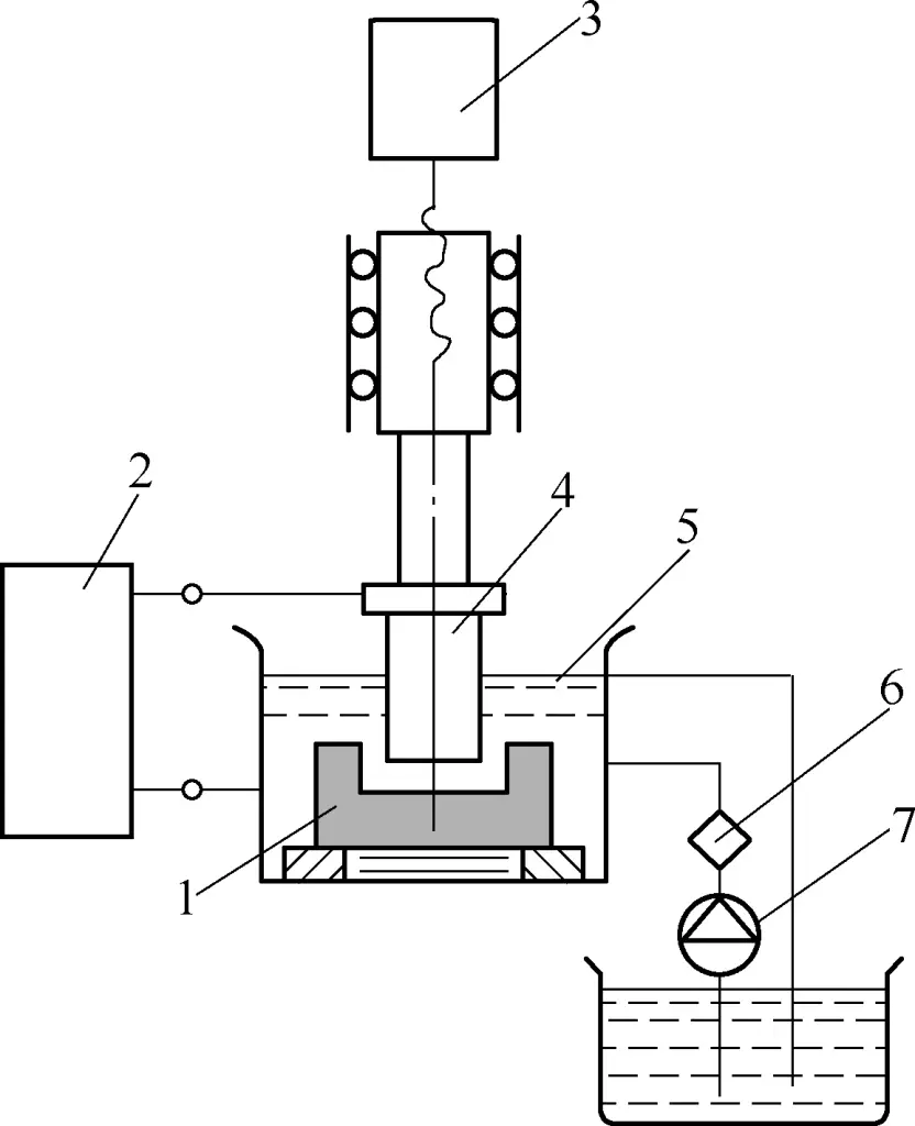
1—Workpiece
2—Pulse power supply
3—Automatic feed adjustment system
4—Tool
5—Working fluid
6—Filter
7—Working fluid pump
Under the action of pulse voltage, the insulation at the minimum gap or the weakest insulation strength is instantaneously broken down, producing instantaneous high temperatures that cause local melting or even sublimation of the surface metal, forming an electro-eroded crater.
After the first pulse discharge ends, there is an interval time to allow the working fluid to restore its insulation. Then, the second pulse voltage is applied to the two poles, and another small crater will be eroded at the relatively closest distance between the electrodes.
This high-frequency cycle repeats continuously, with the tool electrode constantly feeding into the workpiece, thus copying the tool’s shape onto the workpiece, machining the required part. The entire machined surface will be composed of countless small pits.
Electrical discharge machining is a metal removal process that gradually accumulates a large number of tiny discharge marks, as shown in Figure 2.

(2) Main characteristics of electrical discharge machining
The main characteristics of electrical discharge machining are:
- Electrical discharge machining is a corrosive process, with no special requirements for the relative hardness of the electrode and workpiece materials; the hardness of the tool electrode material can be lower than that of the workpiece material;
- Electrical discharge machining has no mechanical force, so the workpiece will not deform after machining;
- It can continuously perform rough machining, semi-finishing, and finishing;
- It is easy to implement control and automation;
- The manufacture of tool electrodes has certain difficulties;
- It is only suitable for conductive workpiece materials;
- The efficiency of electrical discharge machining is relatively low.
(3) Scope of electrical discharge machining
The scope of electrical discharge machining includes:
- Various complex-shaped cavities and holes;
- Often used as a finishing process for mold workpieces after quenching;
- Can be used as a surface strengthening method for mold workpieces;
- Can perform electrical discharge grinding;
- Can engrave text and patterns.
2. Electrical discharge machining equipment
(1) Machine composition
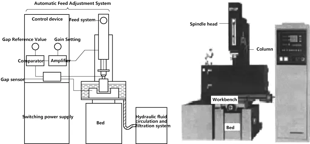
The appearance of an electrical discharge machining equipment is shown in Figure 3, consisting of the machine body, pulse power supply, servo system, working fluid circulation and filtration system, and software operating system.
1) Machine body
The machine body mainly consists of the bed, column, spindle head and accessories, worktable, and other parts, which is a mechanical system used to achieve the clamping, fixing, and movement of the workpiece electrode and tool electrode. The bed, pillar, and coordinate worktable form the framework of the EDM machine, providing support, positioning, and ease of operation.
Because the macroscopic forces in electrical discharge machining are extremely small, there are no strict requirements for the strength of the mechanical system. However, to avoid deformation and ensure accuracy, necessary rigidity is required.
The electrode clamped under the spindle head is the actuator of the automatic adjustment system. Its quality will affect the sensitivity of the feed system and the stability of the machining process, thereby influencing the machining accuracy of the workpiece.
2) Pulse power supply
In the electrical discharge machining process, the function of the pulse power supply is to convert 50Hz mains frequency sinusoidal alternating current into higher frequency unidirectional pulse current, providing the necessary discharge energy to the machining gap between the workpiece electrode and tool electrode to erode metal. The performance of the pulse power supply directly affects the machining speed, surface quality, machining accuracy, tool electrode wear, and other technological indicators of electrical discharge machining.
3) Servo system
Its main function is to control the servo motion of the X, Y, and Z axes.
4) Working fluid circulation and filtration system
The working fluid circulation and filtration system consists of working fluid, working fluid tank, working fluid pump, filter element, and conduits. The working fluid serves the purposes of insulation, chip removal, cooling, and improving machining quality.
After each pulse discharge, the insulation state between the workpiece electrode and tool electrode must be quickly restored, otherwise, the pulse discharge will turn into continuous arc discharge, affecting the machining quality.
During the machining process, the working fluid can quickly flush away the metal chips produced, allowing the machining to proceed smoothly. The working fluid also cools the heated electrodes and workpiece, preventing workpiece deformation.
5) Software operating system
The software operating system can input various parameters of the tool electrode and workpiece electrode and generate programs, dynamically observe changes in machining depth during the process, and perform manual operation machining, among other functions.
(2) Tool electrode
The properties that tool electrode materials should possess:
- Good electrical discharge machining process performance, i.e., high melting point, high boiling point, good electrical conductivity, good thermal conductivity, high mechanical strength, etc.
- Good manufacturing processability, easy to machine to required accuracy and surface quality.
- Abundant sources and affordable prices.
3. Electrical discharge machining process and basic machining laws
(1) Polarity effect
In electrical discharge forming, while the workpiece material is gradually eroded, the tool electrode material is also being eroded. However, even when the same material is used for both positive and negative poles, their erosion amounts are different. This phenomenon is called the polarity effect. If the workpiece is connected to the positive pole of the power supply, it is called positive polarity machining; if the workpiece is connected to the negative pole of the power supply, it is called negative polarity machining.
(2) Influence of electrical parameters
1) Pulse width
When other parameters remain constant, increasing the pulse width reduces tool electrode wear, improves production efficiency, and stabilizes machining.
2) Pulse interval
Decreasing the pulse interval increases the discharge frequency, thereby improving production efficiency.
3) Pulse energy
Under normal conditions, the erosion rate is proportional to the pulse energy.
(3) Main factors affecting electrical discharge machining accuracy
1) Machining taper
The machining taper is mainly related to the number of secondary discharges and the energy of a single pulse. The more discharges and the higher the energy, the greater the machining taper. The number of secondary discharges is mainly related to chip removal conditions, chip removal direction, and machining allowance.
2) Accuracy and wear of the tool electrode
Since electrical discharge machining is a replication process, machining defects in the tool electrode will be directly copied onto the workpiece. Therefore, the manufacturing accuracy of the tool electrode will directly affect the machining accuracy of the workpiece.
3) Clamping and positioning of the electrode and workpiece
The accuracy of clamping, positioning, and alignment will directly affect the machining accuracy of the workpiece.
4) Thermal deformation of the machine
The machining heat generated by electrical discharge machining is very high, causing the machine spindle axis to deviate, thus affecting the machining accuracy of the workpiece.
4. Application example of electrical discharge machining
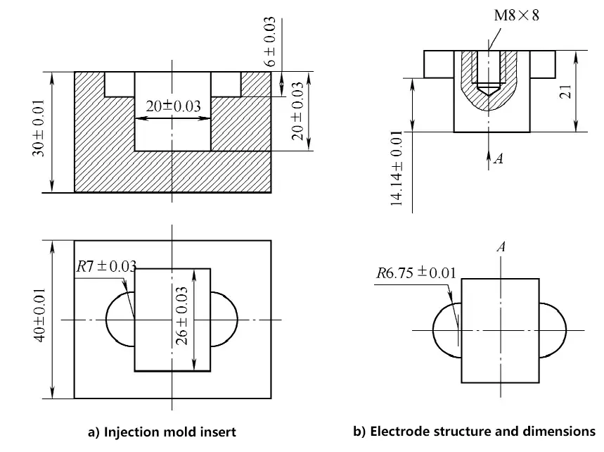
Figure 4a shows an injection mold insert block, made of 40Cr material, with a hardness of 38-40HRC, and a machined surface roughness value of Ra0.8μm. The cavity side edges are required to be sharp, with a corner radius R<0.25mm.
(1) Method selection
Choose the single electrode planetary motion method for electrical discharge forming. To ensure sharp side edges (R<0.3mm), the planetary motion amount should be small, taking δ≤0.25mm.
(2) Tool electrode
1) The electrode material is chosen as forged pure copper to ensure the electrode machining quality and surface roughness.
2) The electrode structure and dimensions are shown in Figure 4b.
① The electrode horizontal dimension single-side scaling amount is taken as b=0.25mm, and according to the relevant calculation formula, the planetary motion amount δ=0.25mm.
② Since the electrode dimension scaling amount is relatively small, the standard parameters for basic forming rough machining should not be too large.
According to the process database (or experience), it is known that the actual rough machining parameters used will produce 1% electrode wear. Therefore, the difference in electrode length corresponding to the 20mm depth of the main cavity and the 6mm depth of the R7mm boss cavity is not 14mm, but (20-6)mm×(1+1%)=14.14mm.
Although there is also wear during finishing, since the finishing amount for both parts is the same, it will not affect the difference in their depths. Figure 4b shows the electrode structure, with no strict requirement for its total length.
3) Electrode manufacturing.
The electrode can be manufactured by mechanical machining methods, but due to the two semicircular bosses, it is generally completed by wire-cut EDM. The main processes are as follows:
- Material preparation;
- Plane upper and lower surfaces;
- Draw lines;
- Machine M8×8 threaded holes;
- Wire-cut according to horizontal dimensions;
- Rotate 90° back and forth in the direction shown in Figure 4b, use wire-cutting to machine two semicircles and the main body length;
- Manual finishing.
4) Processing of insert blank.
Namely:
① Prepare material according to size requirements.
② Plane six faces.
③ Heat treatment (quenching and tempering) to reach 38~40HRC.
④ Grind six faces of the insert.
5) Clamping and positioning of electrode and insert.
① Fix the electrode with M8 screws and clamp it on the spindle head fixture. Use a micrometer (or dial indicator) to align the electrode perpendicular to the workpiece surface, using the top and side surfaces of the electrode as reference, and align its X and Y axes with the X and Y movement directions of the worktable.
② The insert is generally clamped with a machine vise, and its X and Y axes are aligned to match the X and Y movement directions of the worktable.
③ Positioning, which ensures that the centerline of the electrode and the insert are perfectly aligned. When using a CNC EDM machine, the machine’s automatic centering function can be used for accurate positioning.
6) EDM forming process.
III. CNC Wire-cut Electrical Discharge Machining Technology
Wire-cut Electrical Discharge Machining (WEDM) is a new technology developed based on electrical discharge machining, named so because it uses a wire electrode (molybdenum wire or copper wire) to cut the workpiece through spark discharge.
1. Basic principles, characteristics, and processing range of CNC wire-cut electrical discharge machining
(1) Basic principles of CNC wire-cut electrical discharge machining
The basic principle of CNC wire-cut electrical discharge machining is shown in Figure 5.

It utilizes the electro-erosion effect produced by pulsed spark discharge between a moving metal wire (molybdenum wire, copper wire) and the workpiece, which form two electrodes, to process the workpiece and achieve the desired shape.
During the machining process, the workpiece being processed serves as the workpiece electrode, and the molybdenum wire or copper wire serves as the tool electrode. The pulse power supply emits a series of pulse voltages applied to the workpiece and molybdenum wire. There is a sufficient amount of working fluid with certain insulating properties between the molybdenum wire and the workpiece.
When the distance between the molybdenum wire and the workpiece becomes small enough (about 0.01mm), under the action of pulse voltage, the working fluid is ionized and broken down, forming an instantaneous discharge channel between the molybdenum wire and the workpiece. This produces instantaneous high temperatures, causing the metal to melt locally or even sublimate and be eroded away. If the worktable continuously feeds the workpiece, it can cut the desired shape.
(2) Main characteristics of CNC wire-cut electrical discharge machining
1) Since the electrode tool is a thin wire with a small diameter, the pulse width, average current, and other parameters cannot be too large, limiting the range of processing parameters that can be selected.
2) It uses water or water-based working fluid, which won’t ignite or catch fire, making it easy to implement unmanned safe operation.
3) The electrode wire is usually quite thin, allowing for the machining of narrow gaps and complex-shaped workpieces. Due to the narrow cutting gap, the actual amount of metal removal is very small, resulting in high material utilization, which is especially cost-effective when processing precious metals.
4) No need to manufacture shaped tool electrodes, greatly reducing the design and manufacturing costs of shaped tool electrodes, and shortening the production cycle.
5) High degree of automation, easy operation, short processing cycle, and low cost.
(3) Application range of CNC wire-cut electrical discharge machining
1) Mold processing.
Suitable for processing various shapes of punch dies. By adjusting different gap compensation amounts, only one programming is needed to cut punch, punch fixing plate, die, and stripper plate.
2) New product prototyping.
In the process of new product prototyping, CNC wire-cut electrical discharge machining can directly cut out parts without the need to make additional molds, greatly reducing manufacturing costs and cycle time.
3) Processing special materials.
For some high-hardness, high-melting-point metal materials that are almost impossible to process using traditional cutting methods, CNC wire-cut electrical discharge machining is both economical and produces good quality results.
2. CNC wire-cut electrical discharge machining equipment
(1) Wire-cut machining machine model and technical parameters
The compilation of Chinese machine tool model numbers is carried out according to the provisions of GB/T 15375—2008 “Method for compiling model numbers of metal-cutting machine tools”, and the machine tool model numbers are composed of Chinese pinyin letters and Arabic numerals.
For example, the meaning of machine tool model DK7735 is as follows:

The main technical parameters of wire-cut electrical discharge machining machines include: worktable travel (longitudinal travel × transverse travel), maximum cutting thickness, machined surface roughness, cutting speed, and control functions of the CNC system, etc. The main models and technical parameters of the DK77 series wire-cut electrical discharge machining machines are shown in Table 2.
Table 2 Main models and technical parameters of DK77 series machines (for reference)
| Machine model | DK7725 | DK7732 | DK7735 | DK7740 | DK7745 | DK7750 |
| Worktable | 330mm×520mm | 360mm×600mm | 410mm×650mm | 460mm×680mm | 520mm×750mm | 570mm×910mm |
| 250mm×320mm | 320mm×400mm | 350mm×250mm | 400mm×500mm | 450mm×550mm | 500mm×630mm | |
| Maximum cutting thickness/mm | 400 | 500 | 500 | 500 | 500 | 600 |
| Processing load capacity/kg | 250 | 350 | 400 | 450 | 600 | 800 |
| Main machine weight/kg | 1000 | 1100 | 1200 | 1400 | 1700 | 2200 |
| Main machine dimensions | 1400mm× 920mm× 1350mm | 1500mm× 1200mm× 1400mm | 1600mm× 1300mm× 1400mm | 1700mm× 1400mm× 1400mm | 1750mm× 1500mm× 1400mm | 2100mm× 1700mm× 1740mm |
| Surface roughness/μm | 2.5 | |||||
| Machining taper | 3°~60° | |||||
(2) Basic structure of the machine
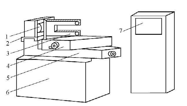
The structural diagram of the wire-cut electrical discharge machining machine is shown in Figure 6, consisting of the machine body, pulse power supply, CNC device, working fluid circulation system, etc.
1—Wire spool
2—Wire-running slide
3—Wire frame
4—Upper worktable
5—Lower worktable
6—Machine bed
7—Pulse power supply and CNC device
1) Machine body
The machine body consists of the bed, wire-running mechanism, worktable, and wire frame, etc.
① Machine bed.
Used to support and connect components such as the worktable and wire-running mechanism, with the machine’s electrical components and working fluid circulation system installed inside.
② Wire-running mechanism.
The motor coupling drives the wire spool to rotate alternately in forward and reverse directions. The molybdenum wire is neatly arranged on the wire spool and moves back and forth at high speed (wire speed about 9m/s) through the wire frame guide wheels.
③ Worktable.
Used to install and drive the workpiece to move in X and Y directions in the horizontal plane. The worktable is divided into upper and lower layers, connected to X and Y lead screws respectively, and driven by two stepper motors.
Each time the stepper motor receives a pulse signal from the computer, its output shaft rotates one step angle, and then drives the lead screw to rotate through a pair of speed-changing gears, thus moving the worktable 0.001mm in the corresponding direction.
④ Wire frame.
The main function of the wire frame is to support the electrode wire as it moves at a set linear speed, and to maintain a certain geometric angle between the working part of the electrode wire and the worktable plane.
2) Pulse power supply
The pulse power supply, also known as high-frequency power supply, mainly functions to convert ordinary 50Hz AC power into high-frequency unidirectional pulse voltage. During machining, the electrode wire is connected to the negative pole of the pulse power supply, and the workpiece is connected to the positive pole.
3) CNC device
The main functions of the CNC device are trajectory control and machining control. Machining control includes feed control, short-circuit retraction, gap compensation, graphic scaling, rotation and translation, adaptive control, automatic centering, information display, self-diagnosis function, etc. Its control accuracy is ±0.001mm, and machining accuracy is ±0.01mm.
4) Working fluid circulation system
Consists of working fluid, working fluid tank, working fluid pump, and circulation pipes. The working fluid serves for insulation, chip removal, and cooling. After each pulse discharge, the insulation state between the workpiece and the electrode wire (molybdenum wire) must be quickly restored, otherwise the pulse discharge will transform into stable continuous arc discharge, affecting the machining quality.
During the machining process, the working fluid can quickly flush away the metal microparticles generated during machining from between the electrodes, ensuring smooth machining. The working fluid can also cool the heated electrode wire and workpiece, preventing workpiece deformation.
3. Process laws of CNC wire-cut electrical discharge machining
The main process indicators of CNC wire-cut electrical discharge machining include cutting speed, machining accuracy, surface roughness, etc.
(1) Cutting speed
Cutting speed refers to the total area of the workpiece surface cut by the center line of the electrode wire per unit time while ensuring a certain surface roughness during the cutting process, measured in mm2/min.
The maximum cutting speed refers to the maximum achievable cutting speed without considering cutting direction, surface roughness, and other conditions. Usually, the cutting speed for fast wire-cut machining is 40~80mm2/min, which is related to the machining current magnitude.
To compare cutting effects under different pulse power supplies and different machining currents, the cutting speed per ampere of current is called cutting efficiency, which is generally 20mm2/(min·A).
(2) Machining accuracy
Machining accuracy refers to the collective term for the dimensional accuracy, shape accuracy, and positional accuracy of the machined workpiece.
Machining accuracy is a comprehensive indicator that includes the control accuracy of the cutting trajectory, mechanical transmission accuracy, workpiece clamping and positioning accuracy, as well as the effects of pulse power supply parameter fluctuations, electrode wire diameter errors, wear and vibration, working fluid contamination level changes, and operator skill level on machining accuracy.
(3) Surface roughness
In China, surface roughness is commonly expressed as the arithmetic mean deviation of the profile Ra(μm), while in Japan, Rmax is often used.
The surface roughness of high-speed wire-cut can reach Ra5.0~2.5μm, with the best achieving around Ra1.0μm; the surface roughness of low-speed wire-cut generally can reach Ra1.25μm, with the best achieving Ra0.2μm.
4. CNC wire-cut electrical discharge machining programming
The control system of CNC wire-cut electrical discharge machining machines controls the machine to perform machining based on human “commands”, so it is necessary to first “write” the commands for the shapes to be machined in a “language” that the wire-cut control system can understand.
Programming methods are divided into manual programming and computer-aided programming. Manual programming is a basic skill for wire cutting operators, allowing you to understand more clearly the various calculations required for programming and the principles and processes of programming.
However, due to the tedious and time-consuming nature of manual programming calculations, with the rapid development of computers in recent years, wire cutting programming mostly adopts computer-aided programming, greatly reducing the labor intensity of programming and significantly reducing the time required for programming.
(1) Manual programming
Wire cutting program formats include 3B, 4B, ISO, etc., with 3B format being the most commonly used. To align with international standards, some manufacturers are also using ISO codes. The 3B program format is shown in Table 3.
Table 3 3B Program Format
| B | X | B | Y | B | J | G | Z |
| Separator | X-axis coordinate | Separator | Y-axis coordinate | Separator | Count length | Count direction | Processing instruction |
1) Determination of coordinate system and coordinate values X, Y.
The plane coordinate system is defined as follows: Facing the machine tool operating platform, the worktable plane is the coordinate plane, with the left-right direction as the X-axis (positive to the right), and the front-back direction as the Y-axis (positive to the front).
The origin of the coordinate system is defined as: When processing a straight line, the starting point of the line is taken as the origin of the coordinate system, and X, Y take the absolute values of the coordinates of the line’s endpoint; when processing an arc, the center of the arc is taken as the origin of the coordinate system, and X, Y take the absolute values of the coordinates of the arc’s starting point.
The unit of coordinate values is micrometers (μm). Relative coordinate system is used in programming, meaning the origin of the coordinate system changes with different program segments.
2) Determination of counting direction G.
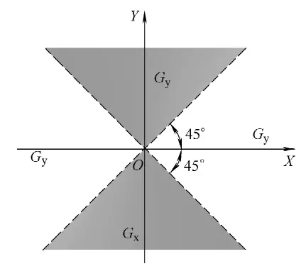
Whether processing a straight line or an arc, the counting direction is determined by the position of the endpoint. The specific principles are: Select the total feed length in the X direction for counting, called counting X, denoted as Gx; select the total feed length in the Y direction for counting, called counting Y, denoted as Gy. That is:
① For processing a straight line, it can be selected according to Figure 7: When | Ye |>| Xe |, choose Gy; when | Xe |>| Ye |, choose Gx; when | Xe |=| Ye |, either Gx or Gy can be chosen.
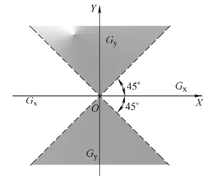
② For arcs, when the arc endpoint coordinates are in the areas shown in Figure 8: When | Xe |>| Ye |, choose Gy; when | Ye |>| Xe |, choose Gx; when | Xe |=| Ye |, either Gx or Gy can be chosen.
3) Determination of count length J. The count length is determined based on the count direction. It is the sum of the absolute values of the projections of the processed straight line or arc on the coordinate axis in the count direction, with the unit being micrometers (μm).
[Example 1] Processing the diagonal line OA as shown in Figure 9, with endpoint A (Xe, Ye), and Ye>Xe, determine G and J.
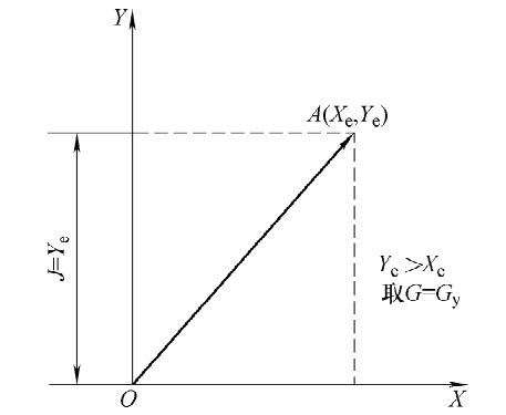
Solution: Because | Ye |>| Xe |, diagonal line OA is on a line with an angle greater than 45° to the X-axis, the count direction is Gy, the projection length of diagonal line OA on the Y-axis is Ye, so J=Ye.
[Example 2] Processing the arc AB as shown in Figure 10, with the starting point in the fourth quadrant and endpoint B (Xe, Ye) in the first quadrant, determine G and J.
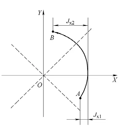
Solution: Because the processing endpoint is close to the Y-axis, | Ye |>| Xe |, the count direction is Gx, the count length is the sum of the projection lengths of the arc segments in each quadrant on the X-axis, i.e., J=Jx1+Jx2.
4) Processing instruction Z.
The processing instruction Z is used to express information such as the shape of the processed figure, the quadrant it’s in, and the processing direction. Based on these instructions, the control system correctly selects the deviation formula, performs deviation calculations, controls the feed direction of the worktable, thus achieving automatic processing of the machine tool. There are 12 types of processing instructions, as shown in Figure 11.
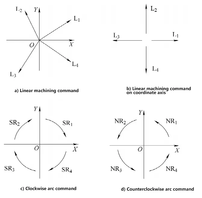
Line segments located in the four quadrants are called diagonal lines. The processing instructions for diagonal lines are represented by L1, L2, L3, L4 respectively, as shown in Figure 11a. For straight lines coinciding with coordinate axes, the processing instructions can be selected according to the feed direction, as shown in Figure 11b.
When processing arcs, if the starting point of the processed arc is in one of the four quadrants of the coordinate system and interpolated clockwise, as shown in Figure 11c, the processing instructions are represented by SR1, SR2, SR3, SR4 respectively; for counterclockwise interpolation, they are represented by NR1, NR2, NR3, NR4 respectively, as shown in Figure 11d. If the starting point is exactly on a coordinate axis, the instruction can be chosen from either of the adjacent two quadrants.
5) 3B code programming example.
Use wire cutting to process the workpiece shown in Figure 12. The tool setting position must be outside the workpiece, with point G coordinates (-20, -10) as the starting point, and point A coordinates (-10, -10) as the cutting start point. For ease of calculation, the molybdenum wire radius compensation value is not considered in programming. That is:
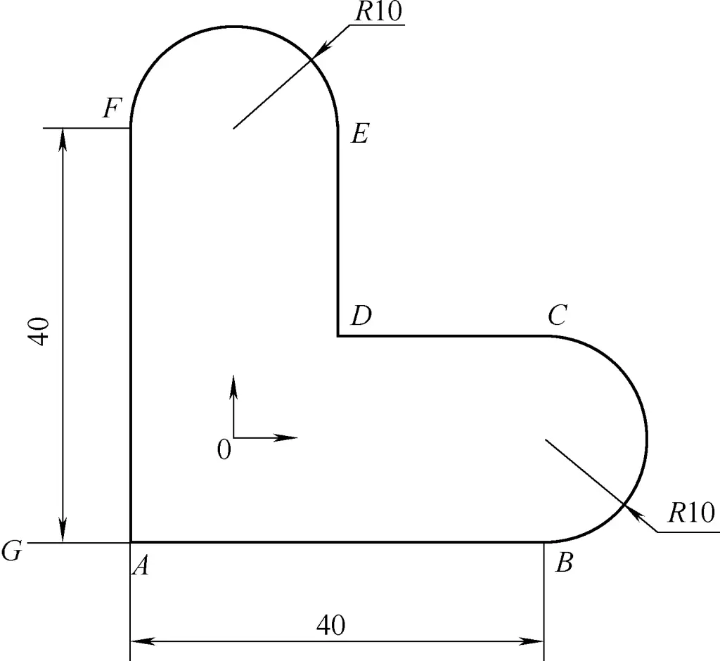
① Determine the processing start point as point G, and the processing route as G—A—B—C—D—E—F—A—G.
② Calculate coordinate values, according to the coordinate system and coordinate value regulations, calculate the coordinate values for each program segment separately.
③ Fill in the program sheet, write each segment according to the standard program format.
| Program | Annotation |
| B10000B0B10000GXL1 | Move from point G to point A, point A is the cutting start point; |
| B40000B0B40000GXL1 | From point A to point B; |
| B0B10000B20000GXNR4 | From point B to point C; |
| B20000B0B20000GXL3 | From point C to point D; |
| B0B20000B20000GYL2 | From point D to point E; |
| B10000B0B20000GYNR4 | From point E to point F; |
| B0B40000B40000GYL4 | From point F to point A; |
| B10000B0B10000GXL3 | Return from point A to the starting point G. |
(2) Computer-aided programming
Due to the rapid development of computer technology, many newly produced CNC wire cutting machine tools have computer-aided programming systems.
CAXA wire cutting is a software system for CNC programming of wire cutting machine tools, widely used in the field of wire cutting processing in China. It can provide fast, efficient, and high-quality CNC programming codes for various wire cutting machine tools, greatly simplifying the work of CNC programming personnel.
CAXA wire cutting can quickly and accurately complete work that is difficult to achieve under traditional programming methods, allowing operators to interactively draw the required cutting graphics and generate two-axis wire cutting processing paths with complex shape contours.
CAXA wire cutting supports fast wire cutting machine tools and can output wire cutting processing programs in 3B, 4B, and ISO formats. The general process of its automated programming is: Use CAXA wire cutting’s CAD function to draw processing graphics → Generate processing paths and processing simulation → Generate wire cutting processing program → Transfer the wire cutting processing program to the wire cutting machine tool.
The following example illustrates the operation process using the machining of a convex-concave die. The dimensions of the convex-concave die are shown in Figure 13. The electrode wire for wire-cut EDM is a Φ0.1mm molybdenum wire, with a single-side discharge gap of 0.01mm.
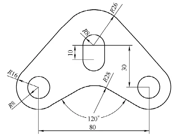
1) Drawing the workpiece diagram
① Drawing circles
- Select the “Basic Curves – Circle” menu item and use the “Center-Radius” method to create circles.
- Enter (0,0) to determine the center position, then input the radius value “8” to draw a circle.
- Without ending the command, while the system is still prompting “Input a point on the arc or radius”, enter “26” to draw a larger circle, then right-click to end the command.
- Continue using the above command to create circles, enter the center point (-40,-30), and input radius values “8” and “16” respectively to draw another set of concentric circles.
② Drawing straight lines
- Select the “Basic Curves – Straight Line” menu item, choose the “Two-Point Line” method, and the system will prompt to input the position of the “First point (tangent point, foot point)”.
- Press the spacebar to activate the feature point capture menu, and select “Tangent point” from it.
- Click at an appropriate position on the “R16” circle. At this point, moving the mouse will show the cursor dragging out an imaginary line, and the system will prompt to input the “Second point (tangent point, foot point)”.
- Press the spacebar again to activate the feature point capture menu, and select “Tangent point” from it.
- Then determine the tangent point at an appropriate position on the “R26” circle to easily obtain the external common tangent line of these two circles.
- Select “Basic Curves – Straight Line”, click the “Two-Point Line” icon, and switch to the “Angle Line” method.
- Click the drop-down icon after the second parameter, and select “X-axis angle” from the pop-up menu.
- Click the “Angle=45” icon and input the new angle value “30”.
- Use the previously used method to select “Tangent point”, and click at an appropriate position in the lower right of the “R16” circle.
- After dragging the line to an appropriate position, left-click to complete the line drawing.
③ Creating symmetrical figures
- Select the “Basic Curves – Straight Line” menu item, choose “Two-Point Line”, and switch to “Orthogonal” mode.
- Input (0,0), drag the mouse to draw a vertical straight line.
- Select “Curve Editing – Mirror” from the drop-down menu, using the default “Select Axis Line” and “Copy” methods. The system will prompt to pick elements; click on the two recently generated straight lines and the concentric circles with radii “8” and “16” in the lower left of the figure, then right-click to confirm.
- The system will then prompt to pick the axis line; select the vertical line just drawn, and after confirmation, you will obtain the symmetrical figure.
④ Creating a slot shape
- Select “Curve Editing – Translate” menu item, choose “Given Offset”, “Copy”, and “Orthogonal” methods.
- The system prompts to pick elements; click on the “R8” circle and right-click to confirm.
- The system prompts “X and Y direction offset or position point”, input (0,-10), indicating an X-axis displacement of 0 and a Y-axis displacement of -10.
- Use the aforementioned method of creating common tangent lines to generate the two vertical lines in the figure.
⑤ Final editing
- Select the eraser icon, and the system will prompt “Pick geometric elements”.
- Click on the vertical line and delete it.
- Select “Curve Editing – Transition” menu item, choose “Fillet” and “Trim” methods, and input the “Radius” value “20”.
- As prompted, click on the two lines that form a 30° angle with the X-axis to obtain the required arc transition.
- Select “Curve Editing – Trim” menu item, choose “Quick Trim” method, and the system will prompt “Pick the curve to be trimmed”. Note that you should select the segment to be cut off.
- Left-click on the non-existent line segments respectively to delete them and complete the figure.
2) Trajectory generation and machining simulation
① Trajectory generation
Trajectory generation is a process where the computer automatically calculates the machining trajectory based on the constructed contour, combined with wire-cut EDM technology, given specific machining methods and conditions. The following introduces the wire path generation method for wire-cut EDM using this example:
- Select “Trajectory Generation” item, in the pop-up dialog box, confirm various machining parameters according to default values.
- In this example, the machining trajectory has an offset from the figure contour. When machining the concave die hole, the electrode wire machining trajectory is offset inward from the original figure trajectory for “gap compensation”. When machining the convex die, the electrode wire machining trajectory is offset outward from the original figure trajectory for “gap compensation”. The compensation distance is ΔR=d/2+Z=0.06mm. Enter this value into “First machining amount”, then click the “Confirm” button.
- The system prompts “Pick contour”. This example is a convex-concave die, requiring cutting of both external and internal surfaces. Here we first cut the concave die hole. There are three concave die holes in this example; taking the left circular hole as an example, pick that contour. At this time, the R8mm contour line becomes a red dashed line, and a pair of bidirectional green arrows appear along the contour line at the mouse click position. The system prompts “Select chain picking direction” (chain picking is the system default).
- After selecting the clockwise direction, another pair of green arrows will appear in the direction perpendicular to the contour line, and the system will prompt “Select the cutting side”.
- As the picked contour is a concave die hole, pick the arrow pointing towards the inside of the contour. The system prompts “Input wire threading point position”.
- Press the spacebar to activate the feature point capture menu, select “Circle center” from it, then select on the R8mm circle to determine the circle center as the wire threading point position. The system prompts “Input exit point (press Enter to coincide with wire threading point)”.
- Right-click or press Enter, and the system calculates the machining trajectory for the concave die hole contour.
- At this point, the system prompts to continue “Pick contour”. Complete the machining trajectories for the other two concave dies using the above method.
- The system prompts to continue “Pick contour”. At this time, the machining start segment becomes a red dashed line.
- The system then sequentially prompts “Select chain picking direction”, “Select cutting side”, “Input wire threading point position”, and “Input exit point”.
- Right-click or press [ESC] to end trajectory generation, select the “Trajectory jump” function of the edit trajectory command to connect the above trajectory segments.
② Machining simulation
Pick “Machining Simulation”, select “Continuous” and an appropriate step length value, and the system will fully simulate the entire process from start-up to completion of machining.
3) Generating wire-cut EDM program
Select the “Generate 3B Code” item, then pick the generated machining trajectory to generate the machining code for that trajectory.
4) Code transmission
- Select the “Response Transmission” item, and the system will pop up a dialog box requesting to specify the file to be transmitted (in the case of recently generated code, an immediate menu for selecting the current code or code file will appear in the lower left corner of the screen).
- After selecting the target file, click the “Confirm” button. The system will prompt “Press any key on the keyboard to start transmission (ESC to exit)”. Press any key to start transmitting the machining code file.
5. Basic operations of CNC wire-cut EDM
(1) Technical indicators of CNC wire-cut EDM
1) Cutting speed
The main factors affecting cutting speed are as follows:
① Wire running speed.
The faster the wire running speed, the faster the cutting speed.
② Workpiece material.
The order of cutting speed from high to low is: aluminum, copper, steel, copper-tungsten alloy, hard alloy.
③ Working fluid.
The working fluid for high-speed wire-cut EDM is generally composed of emulsified oil and water. Different brands of emulsified oil are suitable for different process conditions.
④ Electrode wire tension.
If the electrode wire tension is appropriately higher, the cutting speed will increase.
⑤ Pulse power supply.
It can be approximately expressed by the formula
Vw=KTk1.1Ip1.4f
Where Vw is the cutting speed (mm2/min); K is a constant, depending on the process conditions; Tk is the pulse width; Ip is the pulse peak current; f is the discharge frequency.
2) Surface roughness
For workpieces machined by high-speed wire-cut EDM, the general surface roughness is Ra2.5~5μm, with the best being only about Ra1μm.
3) Machining accuracy
Machining accuracy refers to the overall accuracy of the workpiece’s shape, dimensions, and position. The controllable accuracy of high-speed wire-cut EDM is 0.01~0.02μm.
(2) Preparation before cutting
Turn on the main power switch of the machine tool. At this time, the voltmeter pointer on the machine control panel should point to around 220V, and the corresponding indicator light should be on. Please fully lubricate the moving parts of the machine with machine oil. Turn on the CNC device and enter the system main screen.
Check if the positions of the emulsified oil tank and oil return pipe are correct, thread the molybdenum wire and correct its verticality, adjust the travel switch to fully utilize the molybdenum wire; check if the position of the band switch on the operation panel is correct.
1) Preparation of blank
To improve machining accuracy, regardless of cutting convex or concave parts, pre-hole machining should usually be performed at appropriate positions on the blank, i.e., wire threading holes. The position of the wire threading hole is best chosen at known coordinate points or coordinate points that are easy to calculate, to simplify the calculation of control trajectories during programming.
2) Workpiece clamping and wire threading
The clamping method of the workpiece directly affects the machining accuracy. Common clamping devices include pressure plate clamps, magnetic clamps, and indexing clamps. Before installing the workpiece, first determine the reference surface. When clamping the workpiece, the reference surface should be clean and burr-free, with sufficient clamping allowance on the workpiece. The clamping force on the workpiece should be uniform, avoiding deformation or warping. Care should be taken to prevent the workpiece fixture from colliding with the wire frame during machining.
After the workpiece is clamped, wire threading should be performed. Before threading, check if the electrode wire diameter matches the one specified in the programming. If the electrode wire is worn to a certain extent, it should be replaced with a new one. After threading, check if the position of the electrode wire is correct, paying special attention to whether the electrode wire is in the guide wheel groove.
3) Determine the starting cutting point and cutting path
Most parts machined by wire EDM are closed figures, so the starting point of cutting is also the endpoint of the cutting process. To reduce residual marks on the cutting surface of the workpiece, the starting point should be chosen at a corner of the cutting surface, or on a surface with lower precision requirements, or on a surface that is easy to refinish.
When cutting workpieces from solid material, the deformation at the edges and corners of the material is greater. Therefore, when determining the cutting path, the edges and corners of the blank should be avoided as much as possible. A reasonable cutting path should arrange the cutting segment that separates the workpiece from its clamping part at the end of the overall cutting program.
(3) Selection of pulse power supply electrical parameters
The main electrical parameters include pulse width, pulse interval, pulse voltage, and peak current. These parameters play a decisive role in the workpiece surface roughness, accuracy, and cutting speed.
Increasing pulse width, decreasing pulse interval, increasing pulse voltage amplitude, and increasing peak current will all improve cutting speed, but the surface roughness and accuracy of the machining will decrease. Conversely, reducing these parameters can improve surface roughness and increase machining accuracy.
1) Pulse width Ti
Pulse width is one of the determining factors of single pulse discharge, which has a significant impact on machining speed and surface roughness. A larger pulse width results in higher surface roughness value and faster machining speed.
2) Pulse interval To
Adjusting the pulse interval is actually adjusting the duty cycle, that is, adjusting the input power. Increasing the pulse interval is beneficial for removing chips from the kerf, improving machining stability. Adjusting the pulse interval cannot change the single pulse energy, so it has little effect on surface roughness, but it has a significant impact on machining speed. When using rectangular waves, the duty cycle d corresponding to different workpiece machining thicknesses is
d=Ti/To
3) Applied voltage
The applied voltage affects the size of the discharge energy on one hand, and high voltage (>100V) should be used when cutting larger thicknesses. On the other hand, the magnitude of the processing voltage also affects the discharge gap. When the voltage fluctuation is large, it will affect the stability of processing, so a voltage stabilizer should be used when the voltage fluctuation is large.
4) Adjustment of feed rate
Adjusting the feed rate itself does not have the ability to increase processing speed; its role is to ensure processing stability. Proper adjustment of the feed rate can ensure stable processing and obtain good processing quality.
5) Adjustment of wire running speed
The running speed of the electrode wire is related to the cooling of the electrode wire and the chip removal in the kerf. For workpieces of different thicknesses, appropriate wire running speeds should be selected. The thicker the workpiece, the faster the wire running speed.
(4) Test cutting and cutting
For workpieces with high quality requirements, it is best to perform a test cut before formal processing. Through test cutting, various process parameters for formal processing can be determined, and the correctness of program compilation can be checked at the same time.

