Essential Machine Tool Cutting Methods Explained
How do machines create the precise parts we use every day? Machine tool cutting is the key. This article reveals…
How can manufacturers ensure precision and efficiency when working with irregularly shaped parts? Specialized machine tool fixtures hold the key. This article dives into various fixtures like lathe, milling machine, and drill press fixtures, showcasing their design and application. By understanding these tools, manufacturers can improve machining accuracy, reduce production time, and handle complex shapes with ease. Explore how each fixture type contributes to streamlined manufacturing processes and boosts overall productivity.
The lathe is mainly used for machining the inner and outer cylindrical surfaces, conical surfaces, rotating forming surfaces, threaded surfaces, and end faces of parts. Based on these machining characteristics and the position of the fixture on the machine tool, lathe fixtures can be divided into the following two basic types:
In this type of fixture, in addition to various chucks, faceplates, centers, and other general fixtures or machine tool accessories, various mandrels or other special fixtures can be designed according to machining needs. During machining, the fixture rotates with the lathe spindle, and the tool performs the feed motion.
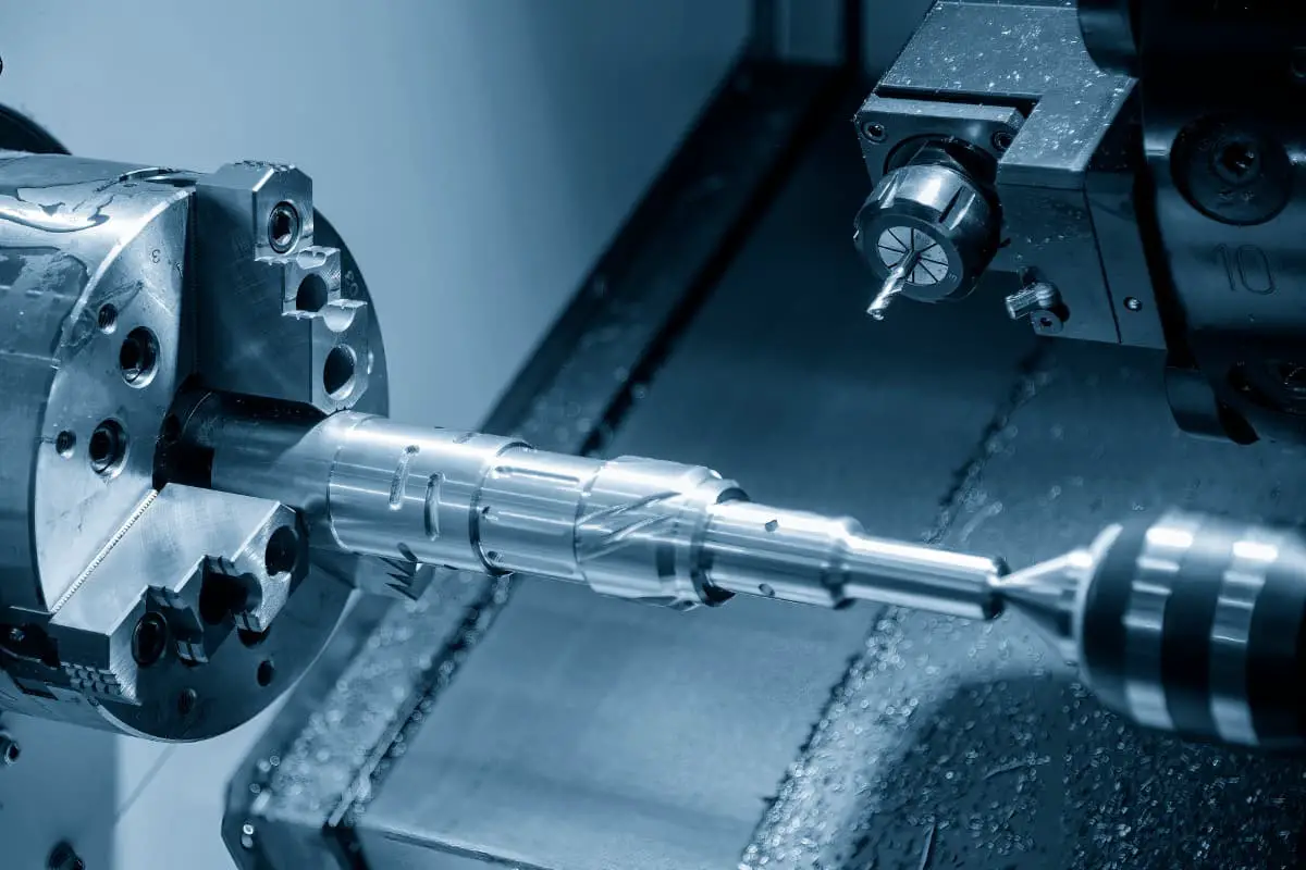
For some irregularly shaped and larger workpieces, the fixture is often mounted on the lathe saddle. The tool is mounted on the lathe spindle for rotational motion, and the fixture performs the feed motion. This section mainly introduces the most widely used lathe special fixtures mounted on the lathe spindle.
In production, it is common to encounter situations where cylindrical surfaces and end faces of parts such as housings, brackets, levers, and joints are machined on a lathe. These parts often have complex shapes, making it difficult to clamp the workpiece directly with a three-jaw self-centering chuck. In such cases, special lathe fixtures need to be designed. The following introduces several typical lathe fixtures.
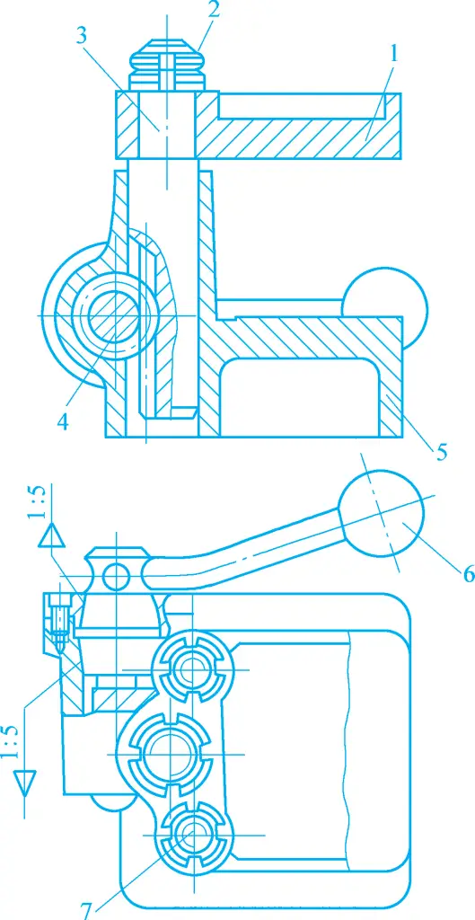
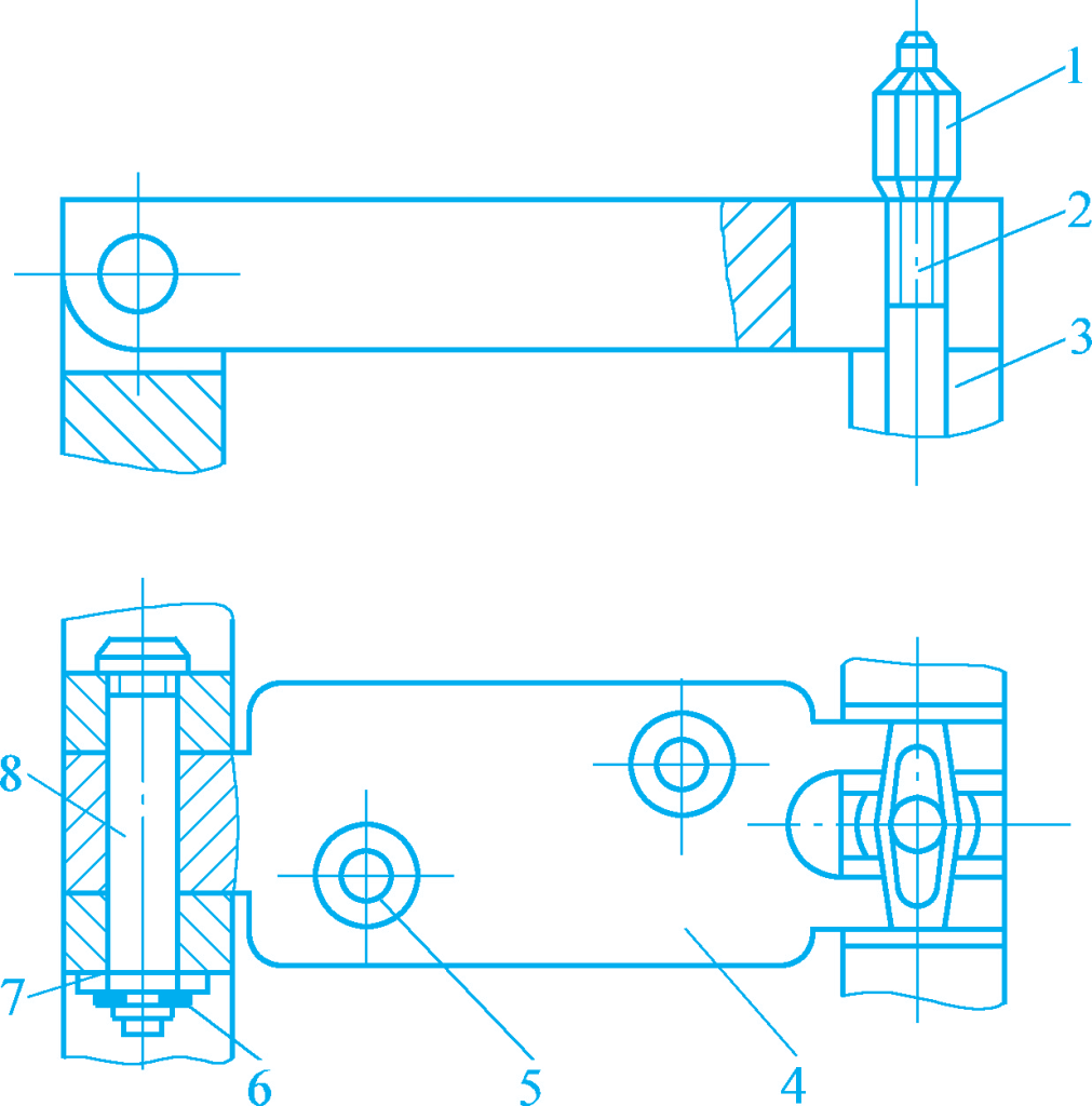
Figure 1 shows an angle iron lathe fixture. The workpiece is positioned on the inclined positioning support plate of the fixture and on a cylindrical pin and a diamond pin using one face and two holes as the positioning reference, and is clamped with two hook-shaped pressure plates.
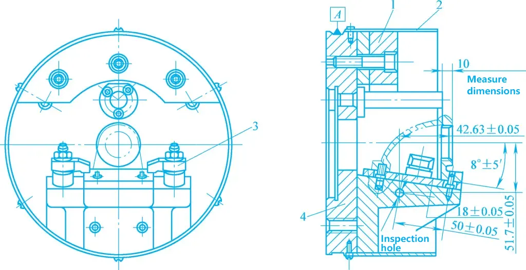
1—Balance block
2—Protective cover
3—Hook-shaped pressure plate
4—Fixture body
The machined surfaces are holes and end faces. To facilitate the inspection of the machined end face dimensions and the angle between the machined hole and the positioning reference surface during machining, a measurement reference surface and process hole are designed near the machining surface. The reference circle A on the fixture body 4 is the alignment circle.
Figure 2 shows the process diagram of the gear pump housing. The outer circle D and end face A of the workpiece have been machined. The machined surfaces are two Φ35mm holes, end face T, and the bottom surface of the hole B, and the relevant technical requirements specified in the part drawing must be met. The diameter accuracy of the two Φ35mm holes mainly depends on the correctness of the machining method, while other technical requirements are ensured by the fixture.
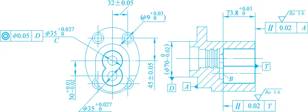
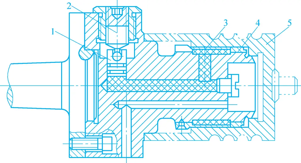
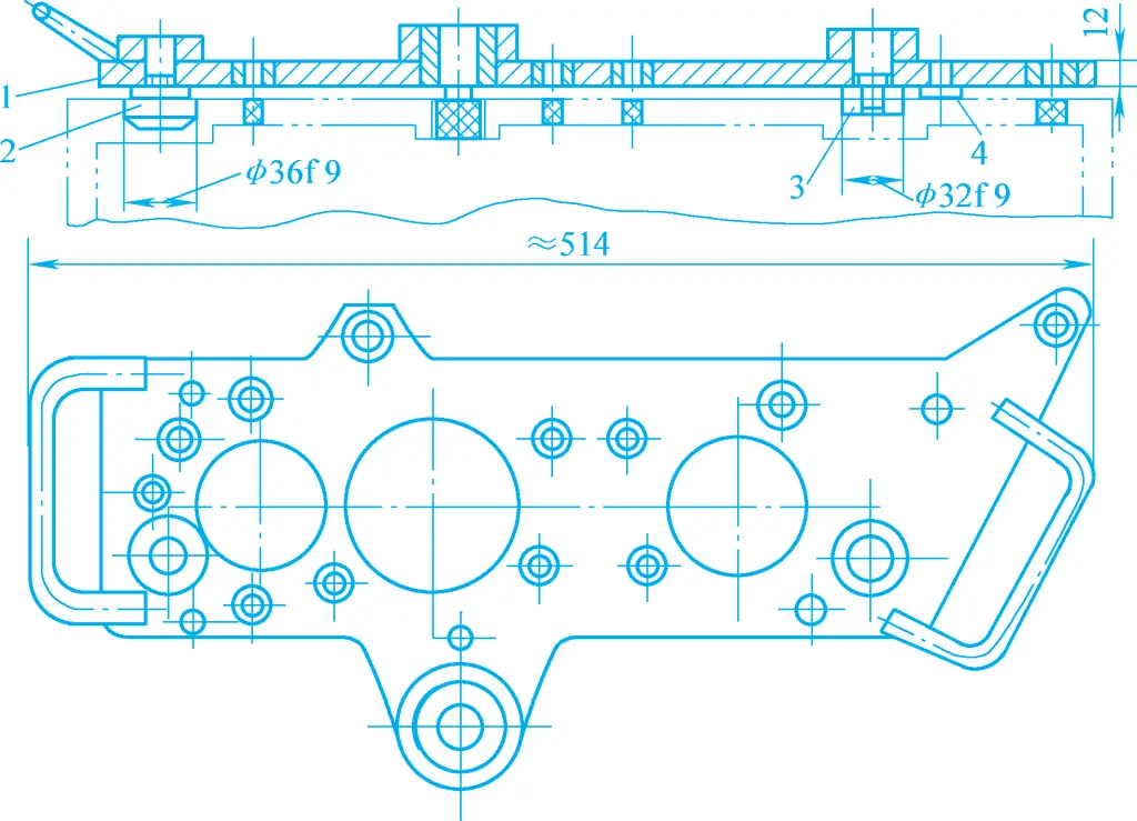
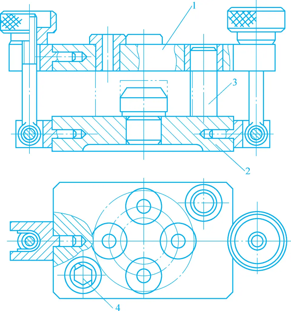
Figure 3 shows the special faceplate fixture used for machining the two Φ35mm holes in the gear pump housing. The workpiece is positioned using end face A, the Φ70mm outer circular surface, and the small hole Φ9mm inner circular surface as the positioning references, and is clamped with two sets of spiral pressure plates 5 on the N surface of the turntable 2, the circular hole Φ70mm, and the trimmed pin 4.
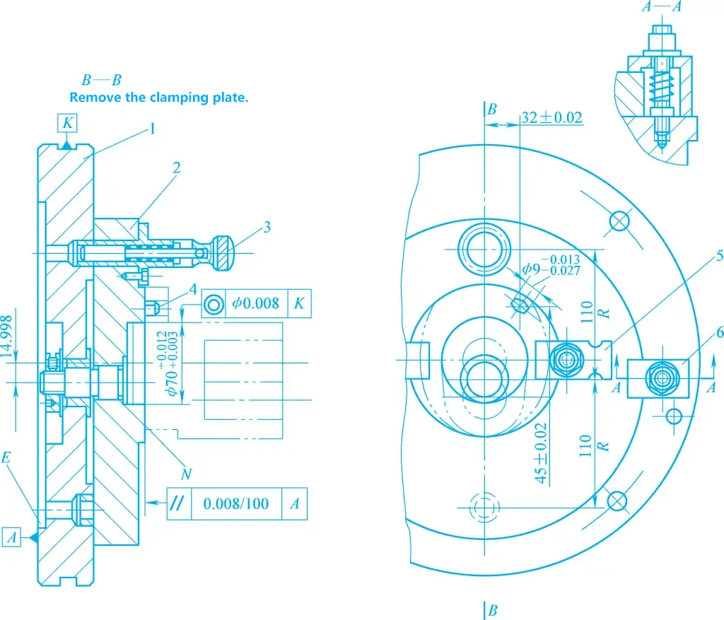
1—Fixture body
2—Turntable
3—Alignment pin
4—Trimmed pin
5, 6—Pressure plates
The turntable 2 is clamped on the fixture body 1 by two sets of spiral pressure plates 6. After machining one of the Φ35mm holes, the alignment pin 3 is pulled out, and the two sets of spiral pressure plates 6 are loosened. The turntable, along with the workpiece, is rotated 180°, and the alignment pin is inserted into another indexing hole on the fixture body under the action of spring force. After clamping the turntable, the second Φ35mm hole can be machined.
The special fixture uses the rabbet E on the fixture body to connect with the lathe spindle through the flange on the transition plate. When installing the fixture, the alignment circle K (representing the rotation axis of the fixture) is used to align the coaxiality of the fixture with the lathe spindle.
For rotary workpieces or workpieces positioned by the rotary surface, centering clamping fixtures can be used. Common types include spring sleeves and liquid plastic fixtures. In the fixture shown in Figure 4, the workpiece is positioned and clamped by the inner hole using a liquid plastic fixture.
1—Sliding Column
2—Compression Screw
3—Liquid Plastic
4—Thin-Walled Positioning Sleeve
5—Workpiece
The workpiece is placed on the positioning cylinder, axially positioned by the end face. By rotating the compression screw 2, the sliding column 1 and liquid plastic 3 cause the thin-walled positioning sleeve 4 to deform, thereby centering and clamping the workpiece 5.
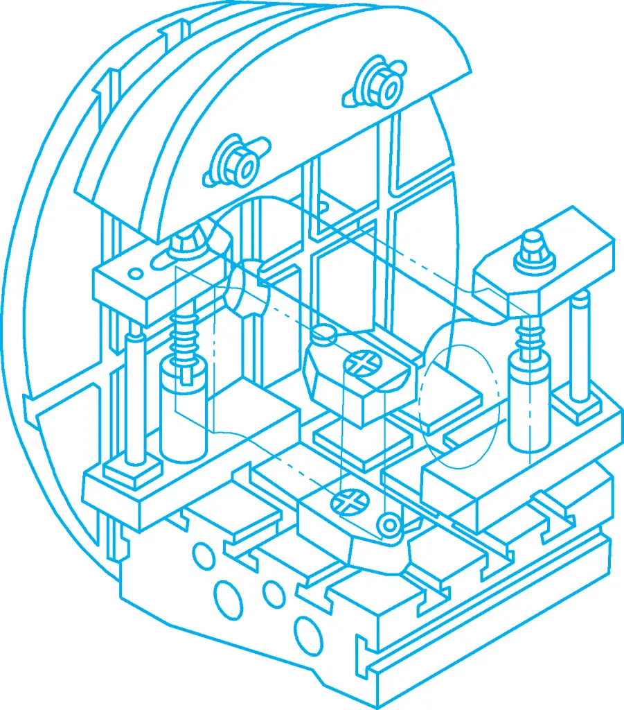
A modular fixture is a special fixture assembled from pre-manufactured standard fixture components according to a designed positioning and clamping scheme. It combines the advantages of special fixtures with the benefits of standardization and generalization. After product changes, the fixture components can be disassembled, cleaned, and stored, avoiding waste. It is suitable for trial production of new products and small batch production of multiple varieties.
It has unique advantages in the production of mechanical products in modern enterprises that extensively use CNC machine tools and apply CAD/CAM/CAPP technologies. Figure 5 shows a typical lathe modular fixture. The workpiece is positioned using the machined bottom surface and two positioning holes, and clamped with two pressure plates. The fixture body, positioning pins, pressure plates, and base are all standard components.
When machining rotary surfaces on a lathe, the axis of the workpiece’s rotary surface must coincide with the rotation axis of the lathe spindle. The structure and arrangement of the positioning device on the fixture must ensure this.
Since the workpiece and fixture rotate together with the spindle during turning, the fixture is subjected to centrifugal force in addition to the cutting torque during machining. The higher the rotational speed, the greater the centrifugal force, which can affect the clamping effect of the clamping mechanism.
Additionally, the position of the workpiece’s positioning reference relative to the direction of cutting force and gravity changes. Therefore, the clamping force generated by the clamping mechanism must be sufficient, and the self-locking performance must be good to prevent the workpiece from detaching from the positioning elements during machining.
The rotational axis of the fixture must have the highest possible coaxial accuracy with the lathe spindle axis. Depending on the radial size of the lathe fixture, there are generally two connection methods with the machine spindle:
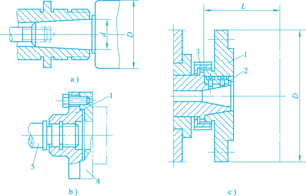
1—Transition Plate
2—Flat Key
3—Nut
4—Fixture
5—Spindle
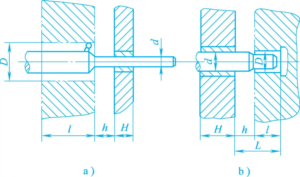
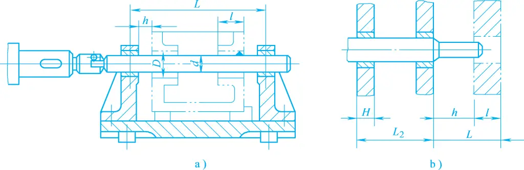
1) For small fixtures with radial dimensions D<140mm, or D<(2~3)d, the connection structure is shown in Figure 6a. They are generally installed in the lathe spindle taper hole through a taper shank and tightened with a bolt rod. This connection method has high centering accuracy.
2) For larger radial dimension fixtures, a transition plate is used to connect to the front end of the lathe spindle. The structure of the transition plate is shown in Figures 6b and 6c. One end of the transition plate connects to the machine spindle, with the mating surface shape depending on the structure of the spindle front end. The other end usually has a flange that mates with the positioning shoulder on the fixture body, achieving centering of the fixture on the spindle.
The fixture body of the lathe fixture should generally have alignment holes or alignment circles, as shown in Figures 1 and 3. The alignment holes or circles serve as the alignment reference to ensure coaxiality when installing the lathe fixture on the lathe spindle, as well as the assembly reference during the manufacturing and assembly of the lathe fixture. They are also often the process reference during the machining of the fixture body itself.
The lathe fixture should eliminate the problem of rotational imbalance. One balancing measure is to add a balance block (counterweight) on the lighter side, another is to machine weight-reducing holes on the heavier side, or a combination of both. The position and weight of the balance block should preferably be adjustable.
To ensure safe operation, the fixture should avoid having sharp corners or components protruding beyond the circular contour of the fixture body as much as possible. If necessary, a protective cover should be added. Additionally, the self-locking performance of the clamping device should be reliable to prevent loosening during rotation, which could cause the workpiece to fly out.
According to different feeding methods, milling machine fixtures are divided into linear feed type, circular feed type, and template type. This section mainly introduces the first two types.
These fixtures are generally installed on the worktable of the milling machine, and during processing, the fixture moves linearly along with the worktable. Depending on the number of workpieces clamped at one time, they can be divided into single-piece milling machine fixtures and multi-piece milling machine fixtures.
Single-piece fixtures are more commonly used in small batch production, while multi-piece fixtures are widely used in the mass production of small to medium-sized parts. Figure 8 shows a double-piece milling machine fixture for milling double slots on the center sleeve shown in Figure 7.
1—Fixture Body
2—Floating Lever
3—Screw Rod
4—Support Pin
5—Hydraulic Cylinder
6—Tool Block
7—Pressure Plate
8, 9, 10, 11—V-Blocks
12—Anti-Rotation Pin
13, 14—Thrust Pins
Circular feed type milling machine fixtures are mostly used on milling machines with rotary tables. When used on general milling machines, a rotary table should be added to the milling machine, as shown in Figure 9.

1—Pull Rod
2—Positioning Pin
3—Split Washer
4—Stop Pin
5—Rotary Table
6—Hydraulic Cylinder
Circular feed motion is continuous, allowing for loading and unloading of workpieces without stopping the machine, thus providing high productivity. It is suitable for the mass production of small to medium-sized parts, but special attention should be paid to operational safety and the labor intensity of the operator.
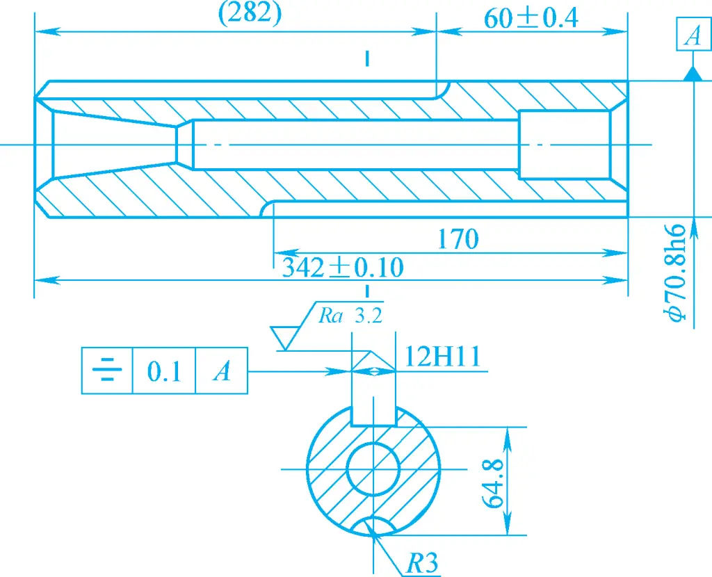
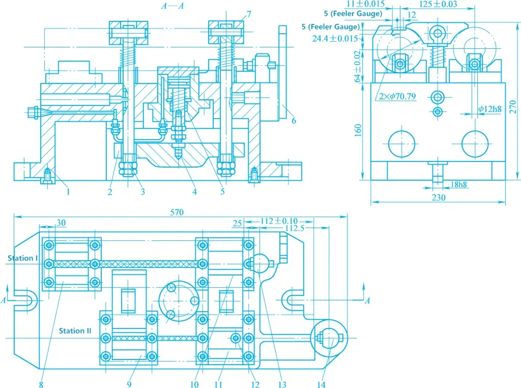
Figure 7 shows the process diagram for milling key slots and oil grooves on the tailstock sleeve of a lathe. The inner and outer circles and both end faces of the workpiece have been machined. In this process, key slots and oil grooves are machined simultaneously using two milling cutters. Figure 8 shows the fixture used in mass production, which is a typical linear feed milling machine fixture.
In station I, a three-sided edge milling cutter is used to mill the key slot. The workpiece is positioned on the V-blocks 8, 10, and thrust pin 13 by its outer circle and end face, restricting five degrees of freedom. In station II, an arc milling cutter is used to mill the oil groove. The workpiece is positioned by its outer circle, the already machined key slot, and the end face, using V-blocks 9, 11, anti-rotation pin 12, and thrust pin 14 for complete positioning.
Since the lengths of the key slot and oil groove are different, to complete the machining simultaneously, the positions of the two thrust pins can be staggered and designed to be adjustable for easy adjustment.
The clamping uses hydraulic-driven linkage clamping. When the pressure oil enters the upper chamber of the hydraulic cylinder 5 from the oil circuit system, it pushes the piston down, driving the hinge pressure plate 7 down through the support pin 4, floating lever 2, and screw 3 to clamp the workpiece. To ensure the pressure plate clamps the workpiece evenly, all parts of the linkage clamping mechanism use floating connections.
The circumferential feed milling machine fixture shown in Figure 9 is used for continuous milling of the upper and lower end faces of the fork on a vertical milling machine. The workpiece is positioned by its round hole, end face, and side face on the locating pin 2 with a boss and the stop pin 4, and clamped by the pull rod 1 driven by the hydraulic cylinder 6 through the split washer 3.
The fixture simultaneously clamps 12 workpieces, and the worktable is driven to rotate by a motor through a worm gear mechanism. The AB sector is the cutting area, and the CD sector is the loading and unloading area. When the workpiece rotates with the worktable to the AB area, the hydraulic cylinder 6 drives the pull rod 1 down to clamp the workpiece; when the workpiece rotates with the worktable to the CD area, the hydraulic cylinder 6 drives the pull rod 1 up to release the workpiece.
During the process of cutting and loading/unloading the workpiece, the worktable continuously rotates without stopping. Therefore, the machining time and the auxiliary time for loading/unloading the workpiece overlap, resulting in high productivity.
Milling machine fixtures generally have locating keys installed in the longitudinal slots on the bottom surface of the fixture body. Usually, two are used, spaced as far apart as possible. Small fixtures can also use a single long key with a rectangular cross-section.
The locating key fits with the T-slot of the milling machine worktable. Its main function is to ensure the correct positional relationship between the fixture and the milling machine worktable. It can also bear part of the cutting torque, reducing the load on the bolts connecting the fixture body to the worktable and enhancing the stability of the fixture during machining.
There are two types of locating keys: rectangular and cylindrical. Common rectangular keys have two structures, as shown in Figures 10a and 10b. The former is used when the fixture’s orientation accuracy requirements are not high. To improve the fixture’s orientation accuracy, one side of the locating key should be tightly fitted against one side of the worktable T-slot when installing the fixture.
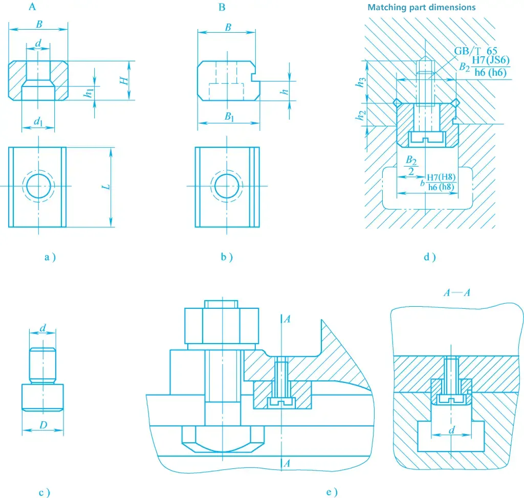
Due to the difficulty in ensuring the accuracy of the key slots on the fixture body, cylindrical locating keys have appeared in recent years, as shown in Figure 10c. When using this type of locating key, the two holes on the fixture are machined on a coordinate boring machine, achieving high positional accuracy and simplifying the manufacturing process of the fixture.
However, cylindrical locating keys are prone to wear and are not widely used in production. Figures 10d and 10e show the installation of locating keys on the fixture body and the installation of milling machine fixtures on the worktable.
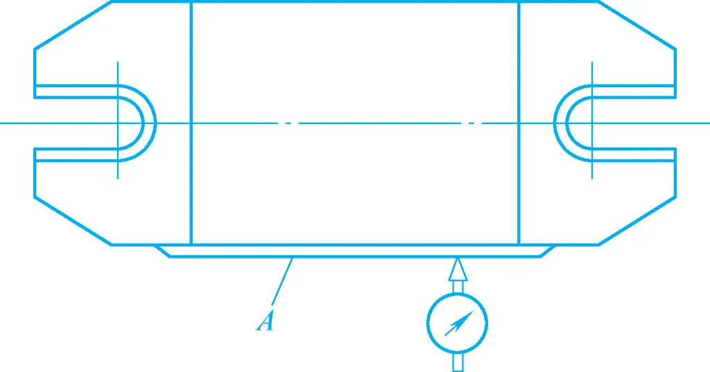
For large fixtures or when high orientation accuracy is required, locating keys are not suitable. Instead, a narrow long plane is machined on the fixture body as a reference surface for alignment to correct the fixture’s installation position, as shown in Figure 11.
Milling machine fixtures generally have a tool setting device, consisting of a tool setting block and a feeler gauge. The tool setting block is used to determine the relative position of the fixture and the tool. The feeler gauge is used to prevent damage to the cutting edge and the tool setting block during tool setting. When in use, it is inserted between the tool and the tool setting block, and the final position of the tool relative to the fixture is determined based on the tightness of the contact.
Figure 12 shows several common tool setting blocks. The round tool setting block shown in Figure 12a is used for tool setting when machining a single plane. The right-angle tool setting block shown in Figure 12b is used for tool setting when machining two mutually perpendicular planes or slots. The tool setting blocks shown in Figures 12c and 12d are used for tool setting when machining forming surfaces with forming milling cutters.
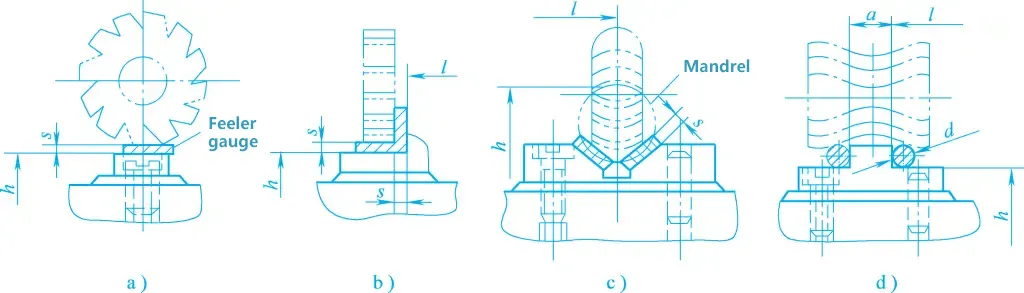
Tool setting blocks are usually fastened to the fixture body with two pins and screws. Their position should facilitate tool setting and not obstruct the loading and unloading or machining of the workpiece. When using a tool setting device for tool adjustment, the accuracy does not exceed IT8. When higher machining accuracy is required or it is inconvenient to set up the tool setting block, methods such as trial cutting, standard part tool setting, or using a dial indicator to align the tool position can be used.
The structural form of the fixture body largely depends on the structure and arrangement of the locating elements, clamping devices, and other components. To make the fixture structure compact and ensure the stability of the fixture installation on the machine tool, the machining surface of the workpiece should be as close to the worktable surface as possible to lower the center of gravity of the fixture, as shown in Figure 13a.
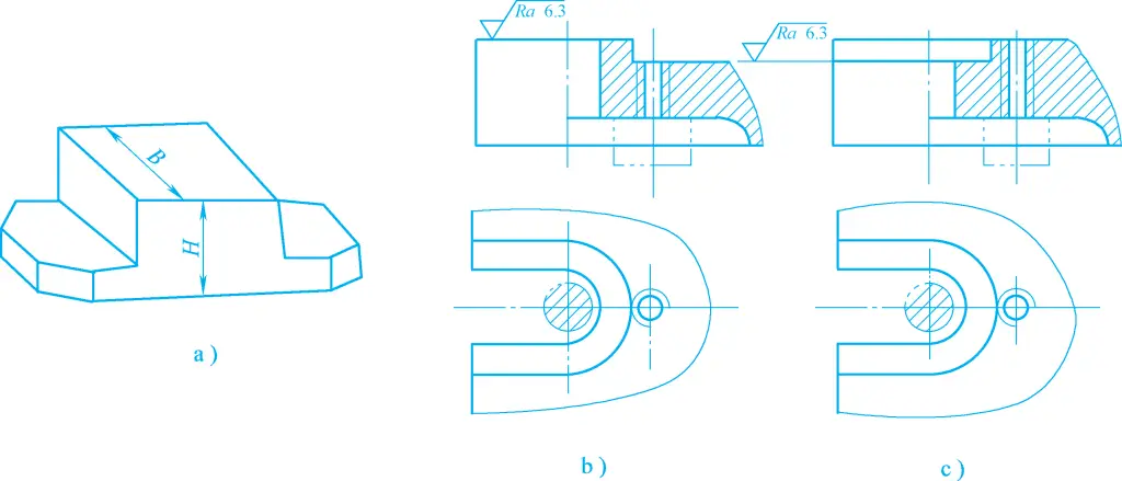
Additionally, the fixture body should have sufficient strength and rigidity, and the lug seats should be reasonably arranged. Common lug seat structures are shown in Figures 13b and 13c. If the fixture body is relatively wide, two lug seats can be arranged on the same side, and the center distance between the two lug seats should match the center distance of the two T-slots on the milling machine worktable. For heavy-duty milling machine fixtures, lifting rings should be set on the fixture body for easy handling.
Drill jigs are machine jigs used on drilling machines for drilling, reaming, and boring. These jigs are equipped with drill templates and drill bushings, guiding the tool through the bushing, hence commonly referred to as drill jigs. Depending on usage requirements, their structural forms can be divided into fixed, rotary, flip, cover plate, and sliding column types.
The characteristic of a fixed drill jig is that its position remains unchanged during processing, ensuring high machining accuracy. Typically, the drill jig is fixed to the drilling machine’s worktable using T-bolts through the ear seat holes on the jig body, or it can be clamped directly to the worktable using bolts and pressure plates. Fixed drill jigs are mainly used for machining larger single holes on vertical drilling machines or parallel hole systems on radial drilling machines.
When using a fixed drill jig to machine parallel hole systems on a vertical drilling machine, a multi-spindle drive head needs to be installed on the machine spindle. When installing the drill jig on a vertical drilling machine, a dimensioned tool (or a mandrel for high precision) mounted on the spindle is generally inserted into the drill bushing to determine the position of the drill jig, which is then secured.
Figure 14a shows a fixed drill jig for machining a Φ10mm hole on a lever. This drill jig can be fixed to the drilling machine’s worktable using bolts and pressure plates.
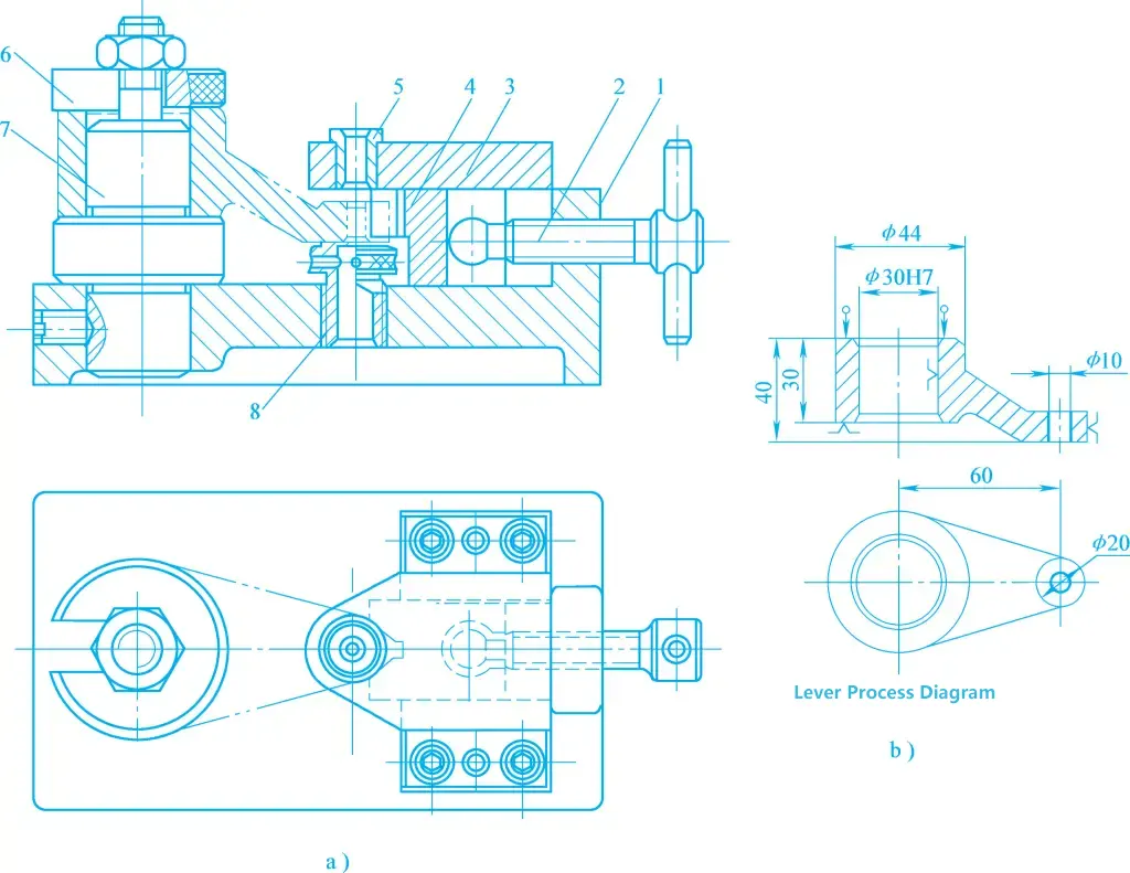
1—Jig Body
2—Fixed Handle Pressure Screw
3—Drill Template
4—Movable V-Block
5—Drill Bushing
6—Split Washer
7—Positioning Pin
8—Auxiliary Support
The workpiece is positioned on the positioning pin 7 using the Φ30H7 hole and the large end face, and the rotation freedom of the workpiece is restricted by the Φ20mm outer circle through the movable V-block 4. The workpiece is clamped using a screw clamping mechanism and a split washer, with the lower end face of the Φ20mm outer circle supported by the auxiliary support 8. The drill bit is guided through the drill bushing 5 to machine the Φ10mm hole.
If such drill jigs are not fixed to the drilling machine’s worktable, they become mobile drill jigs, which can be used on single-spindle vertical drilling machines to successively drill multiple parallel small holes on the same surface of the workpiece.
Rotary drill jigs are named for their rotary indexing devices or their use with general rotary tables. They are used for machining parallel hole systems on the same circumference or radial hole systems distributed on the circumference. Since the structure of general rotary tables has been standardized, in most cases, only special work jigs need to be designed to be used with them. Special rotary drill jigs with dedicated rotary indexing devices are designed only in special cases.
Figure 15a shows a vertical axis rotary drill jig for machining 6×Φ10mm holes evenly distributed on a Φ70mm circumference. The workpiece is positioned using the bottom face, Φ40H7 hole, and keyway side face on the positioning disk 4, positioning pin 3, and key, and clamped using a nut and split washer.
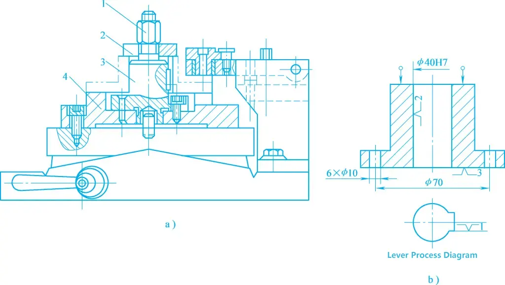
1—Clamping Nut
2—Split Washer
3—Combination Positioning Pin
4—Positioning Disk
The jig is mounted on the positioning pin at the center of the rotary table’s turntable through the bushing hole on the positioning disk, and then secured with screws. Additionally, a hinged drill template is installed on the rotary table, and the 6xΦ10mm holes are sequentially machined through the rotary indexing of the turntable.
This type of drill jig is mainly used for machining small holes distributed on different surfaces of small workpieces. Its structure is simple, and during use, it requires manual flipping. That is, after machining the holes on one surface, the workpiece along with the fixture is flipped and placed, and then the holes on other surfaces are machined.
Since the fixture needs to be frequently flipped during machining and is not fixed on the drill press table, the weight of the fixture along with the workpiece should not be too heavy (generally limited to 8-10kg). The holes machined are generally not larger than Φ10mm, and attention should be paid to the stability of the fixture after flipping and the removal of chips.
Figure 16 shows a flip-type drill jig used for machining four radial small holes on the cylindrical surface of a sleeve. The workpiece is positioned on the locating pin 1 by its end face and hole, and clamped with nut 3 and split washer 2. After drilling one set of holes, the drill jig is flipped 60° to drill another set of holes.
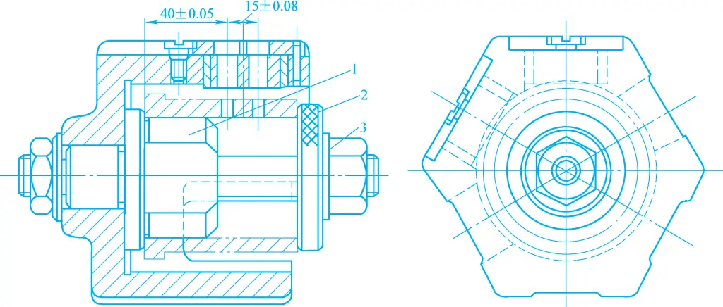
1—Locating Pin
2—Washer
3—Nut
This type of drill jig does not have a fixture body and is often used for machining multiple parallel small holes on large workpieces. Generally, in addition to drill bushings, the drill template is also equipped with locating elements and clamping devices. During machining, it only needs to be placed over the workpiece.
Figure 17 shows a cover plate drill jig used for machining multiple small holes on the lathe carriage. It is positioned in the two holes of the workpiece by cylindrical pin 2 and flat pin 3, and supported on the upper surface of the workpiece by three support pins 4. When the drill template is relatively heavy and the holes being machined are relatively small, clamping may not be necessary during machining.
1—Cover Plate
2—Cylindrical Pin
3—Flat Pin
4—Support Pin
The sliding column drill jig generally consists of a fixture body, sliding column, lifting drill template, and locking mechanism. Its structure has been standardized and generalized. The common parts are mainly the fixture body and drill template. This type of fixture is widely used in production, but the verticality of the drilled holes and the accuracy of the hole spacing are not very high.
Figure 18 shows the universal base of a manual sliding column drill jig. The lifting drill template 1 is connected to the guide holes of the fixture body 5 through two guide columns 7. By turning the operating handle 6, the bevel gear 4 drives the bevel rack shaft 3 to move, allowing the drill template to lift. According to the shape and machining requirements of different workpieces, corresponding locating, clamping elements, and drill bushings can be configured to form a sliding column drill jig.
1—Lifting Drill Template
2—Locking Nut
3—Bevel Rack Shaft
4—Bevel Gear
5—Fixture Body
6—Operating Handle
7—Guide Column
Figure 19 shows a manual sliding column drill jig used for drilling, reaming, and broaching φ20H7 holes on a fork workpiece. The workpiece is positioned on the base 1 by its outer circular end face, bottom face, and rear side face, respectively, using the locating taper sleeve 9, two adjustable supports 2, and cylindrical stop pin 3. These locating elements are all installed on the base 1.
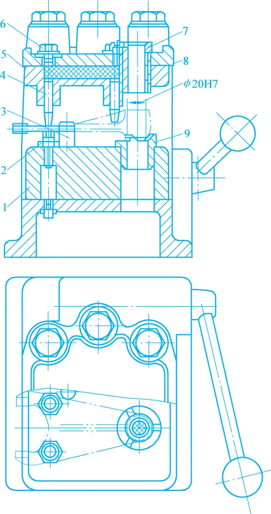
1—Base
2—Adjustable Support
3—Cylindrical Stop Pin
4—Press Column
5—Press Column Body
6—Screw Plug
7—Quick Change Drill Bushing
8—Bushing
9—Positioning Taper Sleeve
Then rotate the handle through the gear rack mechanism, causing the sliding column to drive the drill template down, and the two press columns 4 clamp the workpiece tightly. The tool passes through the quick change drill bushing 7 in sequence, allowing for drilling, reaming, and boring.
The drill bushing is a unique component of the drill jig, its function is to determine the relative position of the tool and the fixture, guiding the drill bit and reamer to prevent deflection during processing and to improve the rigidity of the process system, thereby ensuring the positional accuracy of the processed hole. Its structure has the following four types:
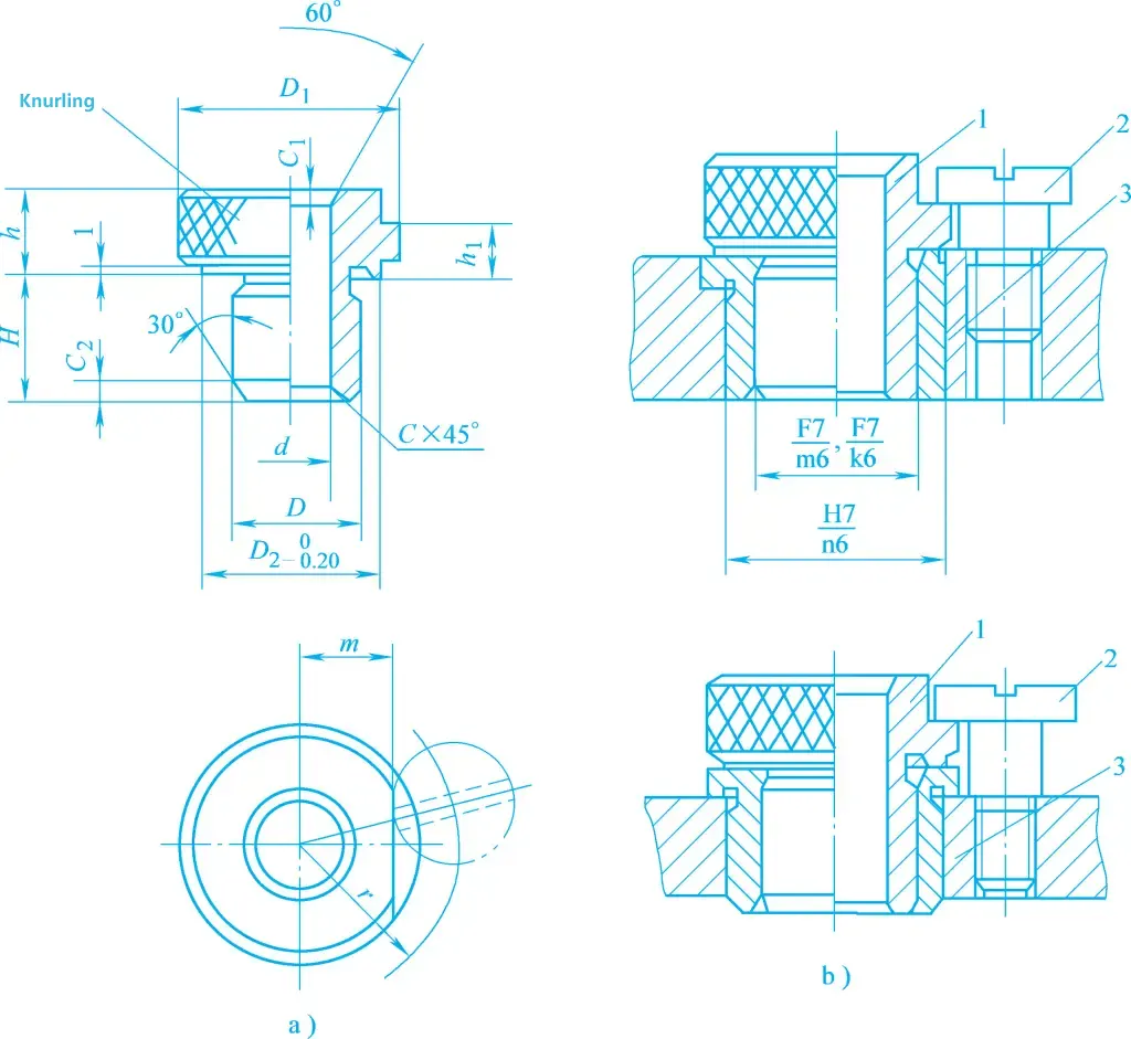
1) Fixed Drill Bushing.
It is mainly used in small to medium batch production. Its structural shape and assembly requirements are shown in Figure 20, where Figure 20a shows a shoulderless drill bushing, and Figure 20b shows a shouldered drill bushing. If the lower end face of the drill bushing shoulder is used as the assembly base surface, or if the drill template is relatively thin and it is necessary to prevent chips and other debris from entering the drill bushing hole, a shouldered drill bushing is often used.
The fit between the drill bushing and the drill template generally uses H7/n6 or H7/r6. This type of drill bushing has high positional accuracy for drilling, simple structure, but is not easy to replace after wear.
2) Replaceable Drill Bushing.
It is mainly used in mass production. When the drill bushing is worn, for easy replacement, a replaceable drill bushing with the structural shape and assembly requirements shown in Figure 21 is often used. To avoid wear of the drill template when replacing the drill bushing, a bushing is added between the drill bushing and the drill template, and the drill bushing is fixed with screws.
1—Replaceable Drill Bushing
2—Screw for Drill Bushing
3—Bushing for Drill Bushing
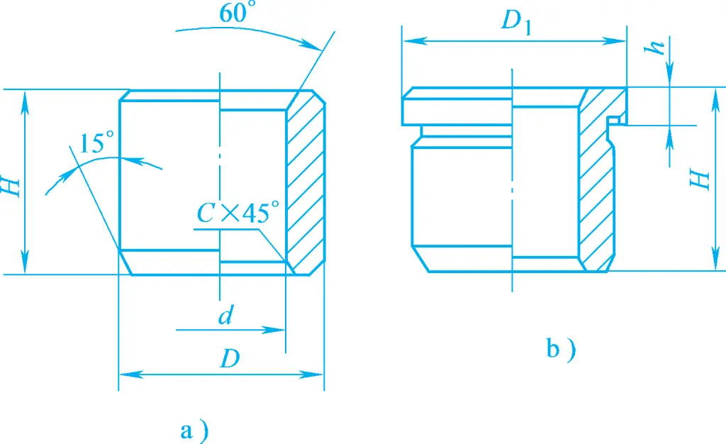
3) Quick Change Drill Bushing.
When the processed hole requires sequential drilling, reaming, boring, or multi-step processing such as step hole processing and tapping, a quick change drill bushing should be used to quickly replace drill bushings with different inner diameters. Its structural shape and assembly requirements are shown in Figure 22.
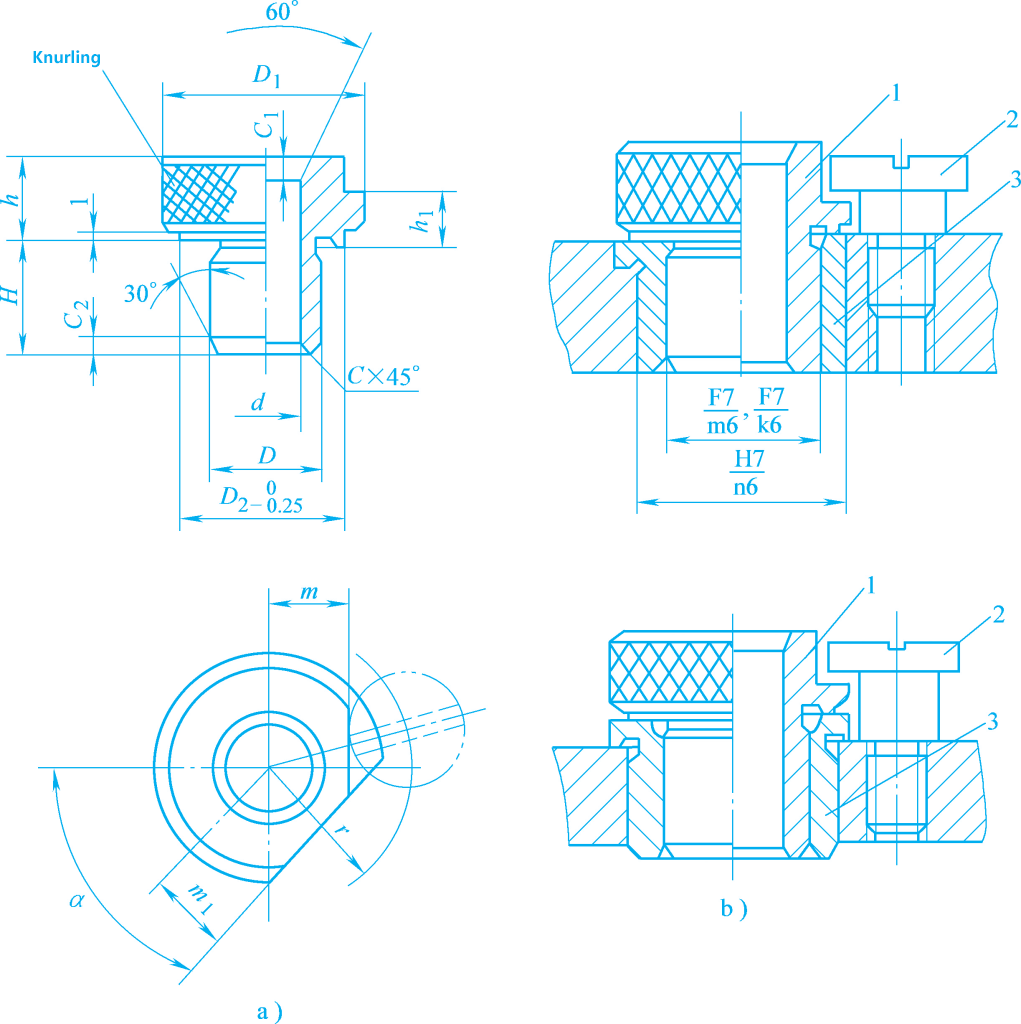
1—Quick Change Drill Bushing
2—Screw for Drill Bushing
3—Bushing for Drill Bushing
When replacing the drill bushing, it is not necessary to loosen the screws. Just rotate the drill bushing to a certain angle so that the chamfer (or notch) aligns with the screw head to remove it. However, the position of the chamfer (or notch) should consider the direction of the friction torque between the tool and the inner wall of the drill bushing to prevent the drill bushing from being pulled out with the tool during retraction.
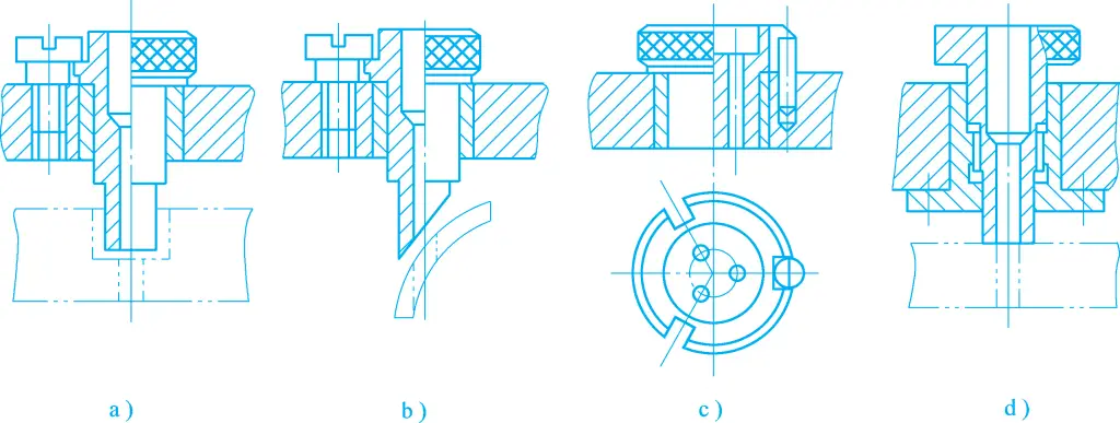
4) Special Drill Bushing.
If the shape of the workpiece or the distribution of the hole positions restricts the use of the above standard drill bushings, special structure drill bushings can be designed as needed.
Figure 23 shows several structural forms of special drill bushings. Figure 23a shows a drill bushing used for machining holes on countersinks or grooves. Figure 23b shows a drill bushing used for drilling holes on inclined or curved surfaces, which can prevent the drill bit from deviating or breaking when cutting in. Figure 23c shows a drill bushing used for machining multiple closely spaced holes. Figure 23d shows a drill bushing used as an auxiliary clamping tool.
To withstand the clamping reaction force, the drill bushing and the sleeve are connected by threads, and there should also be a cylindrical fit between the drill bushing and the sleeve to ensure the correct position of the guide hole.
Drill templates used for installing drill bushings can be divided into the following types based on their connection methods with the fixture body:
1) Fixed Drill Templates
As shown in Figure 24, fixed drill templates are cast integrally with the fixture body or connected to the fixture body with screws and pins. They can also be welded to the fixture body or a bracket. Their structure is simple, and they have high drilling accuracy, but care must be taken not to obstruct the loading and unloading of the workpiece.
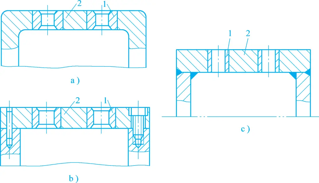
a) Cast integrally
b) Connected with screws and pins
c) Welded
1—Drill Bushing
2—Drill Template
2) Hinged Drill Templates
When the drill template obstructs the loading and unloading of the workpiece or when threading or countersinking is required after drilling, a hinged drill template as shown in Figure 25 can be used.
1—Rhombic Nut
2—Toggle Bolt
3—Fixture Body
4—Drill Template
5—Fixed Drill Bushing
6—Cotter Pin
7—Washer
8—Hinge Pin
Due to the fit clearance between the hinge pin and the hole, the machining accuracy it can ensure is lower than that of fixed drill templates, so it is used in situations where the drilling position accuracy is not high. The position of the hinged drill template is fixed during operation, so the structural requirements for positioning and clamping need to be considered.
3) Removable Drill Templates
As shown in Figure 26, the drill template is positioned on the cylindrical pin 3 and the flat pin 4 on the fixture body through two holes and clamped together with the workpiece using a hinge bolt. After machining one piece, the drill template is removed to load and unload the workpiece. This type of drill template is time-consuming and labor-intensive to load and unload, and the position accuracy of the drill bushing is relatively low, so it is generally used only when other types of drill templates are inconvenient for clamping the workpiece.
1—Drill Template
2—Clamp Body
3—Cylindrical Pin
4—Edge Cutting Pin
Boring machine fixtures, also known as boring jigs, are mainly used for machining holes or hole systems on parts such as boxes and supports. The positional accuracy of the holes or hole systems on the workpiece is mainly ensured by the boring jig. According to the different arrangements of the boring sleeves, boring jigs can be divided into three types: single support, double support, and no support.
The boring bar is guided by only one boring sleeve located either in front of or behind the tool in the boring jig. The boring bar is rigidly connected to the machine spindle, and the centerline of the boring sleeve should coincide with the spindle axis. In this case, the rotational accuracy of the machine spindle will affect the boring accuracy. This type of boring jig is suitable for machining short holes and small holes.
Figure 27a shows a single support front guide, mainly used for through holes with D>60mm and l/D<1. This method facilitates observation and measurement during the machining process and is particularly suitable for facing or threading operations. The disadvantage is that chips can easily enter the boring sleeve, causing wear on the boring bar and sleeve; the tool has a longer travel distance when entering and exiting the workpiece.
a) Single Support Front Guide
b) Single Support Rear Guide
Figure 27b shows a single support rear guide, mainly used for boring through holes or blind holes with D<60mm.
The boring bar is flexibly connected to the machine spindle, and the positional accuracy of the boring hole is determined by the positional accuracy of the boring sleeves. There are two arrangements for the boring sleeves, as shown in Figure 28. Figure 28a shows two boring sleeves arranged at the front and rear of the workpiece, used for machining holes with larger diameters and l/D>1.5, or a set of coaxial holes, where high accuracy is required for both the holes themselves and the distances between them.
The disadvantage of this structure is that the boring bar is too long, making tool loading and unloading inconvenient. When the distance between the boring sleeves L>10d, an intermediate guide support should be added to increase the rigidity of the boring bar. Figure 28b shows a double support rear guide, used when front and rear double guide structures cannot be used due to machining conditions, with two boring sleeves arranged behind the tool.
When boring holes on workpieces with good rigidity and high precision on coordinate boring machines, machining centers, or diamond boring machines, the fixture does not set boring sleeves, and the size and positional accuracy of the machined holes are ensured by the machine’s precision.
Figure 29 shows the process diagram of a bracket housing. This workpiece requires machining 2×Φ20H7 coaxial holes and Φ35H7, Φ40H7 coaxial holes. The assembly reference for the workpiece is the bottom surface a and the side surface b. The holes machined in this process are of IT7 grade accuracy, with some geometric tolerance requirements.
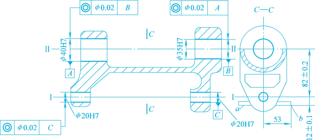
Therefore, special boring machine fixtures are used for rough and finish boring of Φ40H7 and Φ35H7 holes, and drilling, reaming, and honing of 2×Φ20H7 holes. At this time, the hole distance (82±0.2)mm should be ensured by the manufacturing accuracy of the boring jig. According to the principle of reference coincidence, the positioning references are selected as the two planes a and b.
As shown in Figure 30, the boring machine fixture for the bracket housing includes a support plate 10 (one of which has a side face) and a stop pin 9 as positioning elements. During clamping, the pressure plate 8 is pressed against the side plates of the workpiece, making the workpiece gravity and clamping direction consistent.
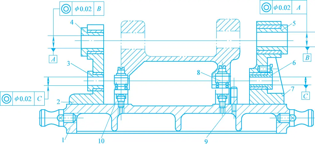
1—Fixture Body
2, 7—Guide Bracket
3, 4, 5, 6—Boring Sleeve
8—Pressure Plate
9—Stop Pin
10—Support Plate
When machining Φ40H7 and Φ35H7 holes, the boring bar is supported on boring sleeves 4 and 5. When machining Φ20H7 holes, the boring bar is supported on boring sleeves 3 and 6. The boring sleeves are mounted on guide brackets 2 and 7. The bracket is fixed to the fixture body 1 with pins and screws.
The structure of the boring sleeve is divided into fixed and rotary types.
1) Fixed Boring Sleeve
The boring sleeve that does not rotate with the boring bar during the boring process has the same structure as the quick-change drill bushing. Figure 31a shows a boring sleeve with a press-fit oil cup, with an oil groove in the inner hole, which can appropriately increase the cutting speed during machining. Since the boring bar rotates and moves axially within the boring sleeve, the boring sleeve is prone to wear, so boring sleeves without oil cups are only suitable for low-speed cutting.
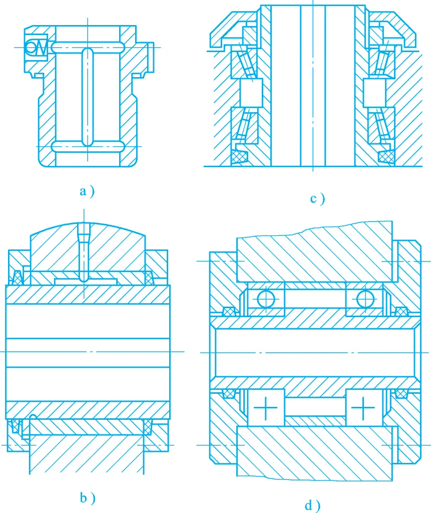
2) Rotary Boring Sleeve
During the boring process, the boring sleeve rotates together with the boring bar, which is particularly suitable for high-speed boring, as shown in Figures 31b, 31c, and 31d. Figure 31b shows a sliding rotary boring sleeve with a keyway in the inner hole, where the key on the boring bar drives the boring sleeve to rotate, providing high rotational accuracy and good vibration damping, with a small structural size and requiring adequate lubrication.
Figures 31c and 31d show rolling rotary boring sleeves, used for vertical and horizontal boring respectively. They have flexible rotation and allow high cutting speeds, but their radial dimensions are relatively large and rotational accuracy is low. If radial dimensions need to be reduced, needle roller bearings can be used.
The boring template bracket and base are made of cast iron and are often manufactured separately, which facilitates processing, assembly, and aging treatment. They must have sufficient strength and rigidity to ensure stability during the machining process. Welding structures should be avoided as much as possible, and rigid connections with screws and pins are preferred.
The bracket should not bear clamping force during use. A narrow long plane should be machined on the side of the base facing the operator to serve as an alignment reference surface when installing the boring template on the workbench. The base should have an appropriate number of lugs to ensure that the boring template is securely and reliably mounted on the machine tool workbench, and lifting rings should be provided for easy handling.