Classification and Characteristics of Resistance Welding
Classification of Welding Methods
Classified by welding methods, spot welding is a type of resistance welding and falls within the category of pressure welding, as shown in Figure 1-1.
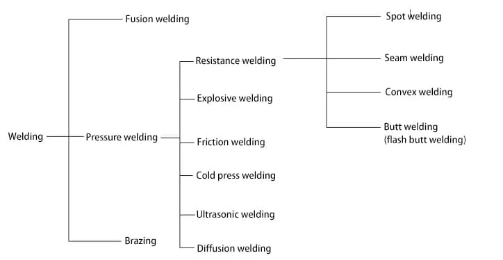
Classification of Welding Methods
Advantages of resistance welding:
1) Heat is concentrated, heating time is short, and welding deformation is small.
2) The metallurgical process is relatively simple.
3) It can adapt to the welding of multiple types of similar and dissimilar metals.
4) The process is simple and easy to mechanize and automate.
5) Welding productivity is high, and costs are low.
6) The working environment is good, with minimal pollution.
Disadvantages:
1) Initial equipment investment is high, equipment is complex, and maintenance personnel require high technical expertise.
2) Requires a large power capacity, often single-phase, which can lead to an unbalanced power grid.
3) Lacks simple and practical non-destructive testing methods.
An overview of the application of resistance welding in automobile production.
In the production of automotive components, various welding processes such as spot welding, projection welding, seam welding, and flash butt welding are widely used. For instance, spot welding is employed in automobile body spot welding, crossbeam assembly bracket spot welding, drive shaft balance piece projection welding, automotive fuel tank seam welding, and continuous flash butt welding of automotive wheel rims.
Spot welding, in particular, is a high-speed, cost-effective joining method suitable for lap joints and joints that do not require gas tightness, as well as for thin-walled components with a thickness of less than 4mm produced by stamping or rolling, requiring the metal to have good plasticity.
This book will focus on the application of spot welding robots and systems in automobile production (see accompanying CD video – (11) Equipment Performance Display of Robot Manufacturing Enterprises).
The Basic Principle of Spot Welding
The formation process of the weld nugget in spot welding
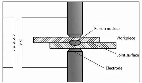
Resistance spot welding, abbreviated as RSW, is a welding method where the assembled workpieces are joined in lap joints and compressed between two electrodes, using resistance heating to melt the base metal and form the weld point, as shown in Figure 1-2.
During spot welding, due to the high resistance at the contact point between the two workpieces, a substantial amount of resistance heat is generated at the contact point when a sufficiently large electric current is passed through the plates. This quickly heats the metal in the central, hottest area to a highly plastic or molten state, forming a lens-shaped liquid weld nugget.
The temperature of the molten zone gradually decreases from the inside to the outside. After the power is cut off, the pressure is maintained or increased to allow the weld nugget to solidify and crystallize under pressure, forming a densely structured weld point, as shown in Figure 1-3.
At the contact point between the electrode and the workpiece, the heat generated is conducted away by the good thermal conductivity of the copper (or copper alloy) electrodes and cooling water, resulting in limited temperature rise and preventing sticking. The formation process of the weld point in spot welding is illustrated in Figure 1-4.
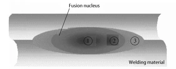
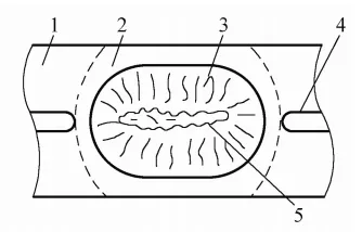
1 – Workpiece 2 – Plastic Zone 3 – Nugget 4 – Sheet Gap 5 – Bonding Surface
Figure 1-3: Schematic Diagram of Spot Weld Nugget Growth and Cross-section
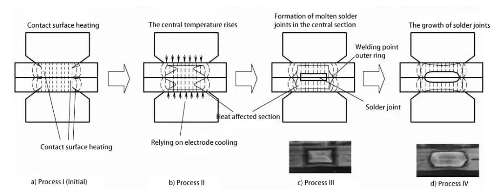
In summary, the two fundamental elements of spot welding are internal heat source and external pressure.
The spot welding process can be summarized into four interconnected stages: in the first stage, the workpieces are pre-compressed between the electrodes; in the second stage, the welding area is heated to a certain temperature after the current is applied; in the third stage, the central portion forms the weld nugget; and in the fourth stage, the weld cools and crystallizes under the pressure of the electrodes, forming the weld point.
During spot welding, due to the pressure applied by electrodes of a certain diameter, the workpiece deforms, and a current path is formed only in the closely contacted welding area, resulting in extremely high current density. Therefore, the applied pressure is related to the workpiece’s rigidity.
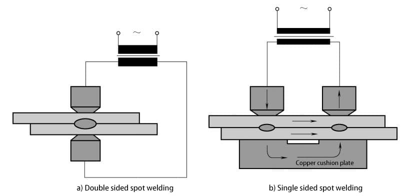
According to the direction of current flow through the workpiece, spot welding is generally divided into two categories: double-sided spot welding and single-sided spot welding. In double-sided spot welding, the two electrodes are located on either side of the workpiece, and the current passes through both sides of the workpiece to form the weld point, which is a commonly used welding method for spot welding robots, as shown in Figure 1-5.
Single-sided spot welding involves the two electrodes being positioned on one side of the workpiece and is used when it is difficult for the electrodes to approach the workpiece from both sides, or when a shallow indentation is required on one side of the workpiece.
Heat Source and Factors Affecting Heating in Spot Welding
(1) Heat Source of Spot Welding
The heat source in resistance spot welding is resistance heat, in accordance with Joule’s law, Q=I2Rt (where Q is the heat generated in joules, I is the welding current in amperes, R is the resistance in ohms, and t is the welding time in seconds).
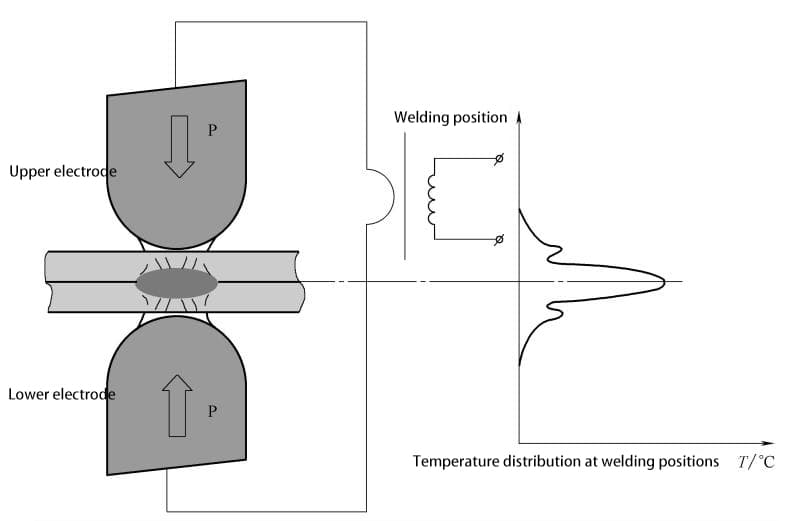
The welding current, the resistance between the two electrodes, and the welding time are the three major factors determining the heat generation (internal heat source) in spot welding, with most of the heat being used to form the weld nugget.
The required welding current and welding time are related to the formation of a specific weld nugget; if the welding time is very short, the required welding current during spot welding will increase, as shown in Figure 1-6.
(2) Heat Balance and Heat Dissipation
During spot welding, only a small portion of the heat generated is used to form the weld nugget, while a larger portion is lost through conduction and radiation to adjacent materials, as shown in Figure 1-7.
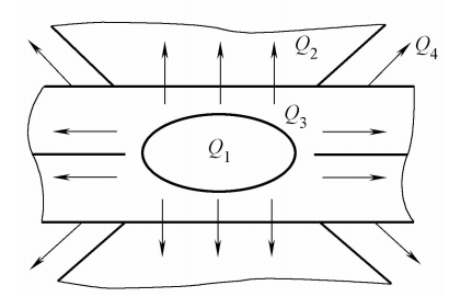
Note: Q1 is the heat input to form the molten pool in the heated welding zone; Q2 is the heat loss through thermal conduction via the electrode; Q3 is the heat loss through thermal conduction in the surrounding metal of the welding zone; Q4 is the heat loss through convection and radiation to the surrounding air medium.
The heat balance equation is Q (total heat) = Q1 + Q2 + Q3 + Q4, where the effective heat Q1 depends on the thermal properties of the metal and the amount of molten metal, independent of the welding conditions, with a reference value of Q1≈10%~30%Q.
For metals with low resistivity and good thermal conductivity (aluminum, copper alloys, etc.), Q1 takes the lower limit; for metals with high resistivity and poor thermal conductivity (stainless steel, high-temperature alloys, etc.), Q1 takes the upper limit.
The lost heat mainly includes the heat conducted through the electrodes (Q2≈30%~50%Q), the heat conducted through the workpiece (Q3≈20%Q), and the heat radiated into the atmosphere (Q4, approximately 5% of the total heat). The characteristics of spot welding are mainly reflected in the following three aspects:
1) Rapid and concentrated heating.
2) Effective heat dissipation in the welding area is crucial to achieve a reasonable temperature distribution.
3) The heating process is closely related to the thermal properties of the metal being welded.
Current Diversion Phenomenon in Spot Welding
During actual spot welding, a small portion of the current flows through the surrounding weld points, forming a current pathway and dissipating into the surrounding metal. The current diversion phenomenon during spot welding is illustrated in Figure 1-8.
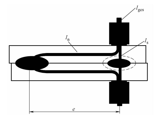
Note: Is=Iges-In where Is is the welding current, Iges is the total electrode current, and In is the diversion current.
The smaller the spot distance, the thicker the plate, and the better the electrical conductivity of the material, the more severe the diversion. Severe diversion can lead to energy loss and difficulties in ensuring welding quality.
Additionally, the surface condition of the workpiece significantly affects the diversion. When the surface treatment is poor, oil stains and oxide films increase the contact resistance, leading to an increase in the total resistance of the welding zone and a relative decrease in diversion resistance, thereby increasing the diversion.Resistance in the Welding Zone and its Variation
The formation of contact resistance is caused by the micro-roughness of the welding surface and the presence of poor conductive layers. The distribution of current lines during spot welding and the situation of current passing through the contact points of the workpieces are illustrated in Figure 1-9.
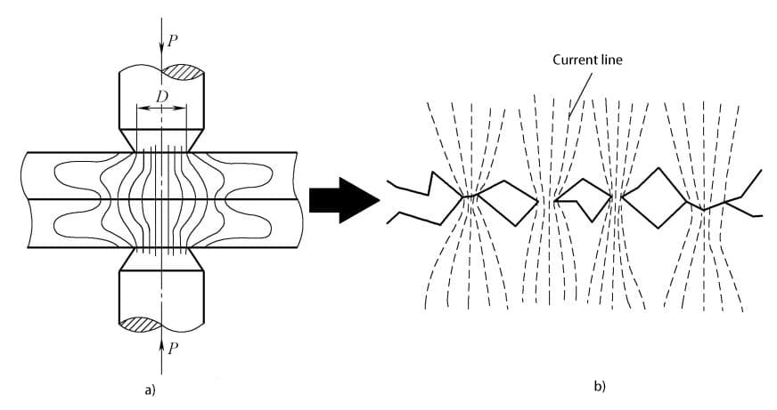
a) Distribution of current lines during spot welding
b) Situation of current passing through the contact points between the workpieces
During spot welding, three types of resistance exist in the welding zone, and the resistance R between the two electrodes varies with different resistance welding methods, as shown in Figure 1-10.
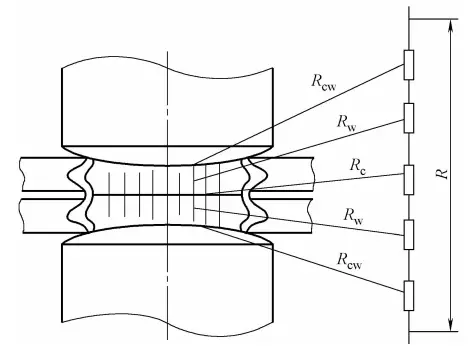
Note: R represents the total resistance of the welding zone; R represents the internal resistance of the workpiece; R represents the contact resistance between the workpieces; R represents the contact resistance between the electrode and the workpiece.
The total resistance R in the spot welding zone is composed of the internal resistance Rw of the two welded parts, the contact resistance Rc between the two welded parts, and the contact resistance Rcw between the electrode and the workpiece, i.e., R=2Rw+Rc+2Rcw. The calculation methods for the resistance values of each part are as follows:
1) Internal Resistance of the Welded Parts (Rw): The resistance generated by the current passing through the welded parts is related to the resistance of the parts themselves. The formula for calculating this resistance is:

where:
- ρ = resistivity of the metal in the welding zone
- δ1, δ2 = thickness of the two welded parts (mm)
- S = corresponding to the electrode contact area (mm2)
- K1 = coefficient due to the edge effect causing the expansion of the current field, ranging from 0.82 to 0.84
- K2 = coefficient due to the bypass effect causing the expansion of the current field, ranging from 0.8 to 0.9; a lower value is chosen for hard specifications, and a higher value for soft specifications.
Since ρ generally increases with temperature, the longer the heating time, the greater the resistance, resulting in more heat generation and a greater contribution to forming the weld.
2) Contact Resistance (Rc+2Rcw): Contact resistance is an additional resistance, usually referring to the resistance value measured at the contact surface (welded part-welded part contact surface, welded part-electrode contact surface) under the pressure of the spot welding electrode.
The main factors affecting contact resistance are surface condition and electrode pressure. The contact resistance at a heating temperature of 600°C for steel and 350°C for aluminum is close to zero.
The contact resistance between the welded parts (Rc), the contact resistance between the electrode and the workpiece (Rcw), the internal resistance of the two welded parts (Rw), the current diversion during spot welding, the welding current, the energizing time, and the electrode pressure all have a significant impact on the heating during spot welding.
The variation curve of the internal resistance of the workpiece during the welding process is shown in Figure 1-11.
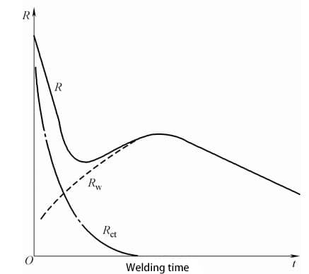
Note: Rw represents the inherent resistance of the workpiece; Rct represents the contact resistance (Rct=Rc+2Rcw); R represents the total resistance of the welding zone (R=Rw+Rct).
The relationship between contact resistance and electrode pressure is shown in Figure 1-12.
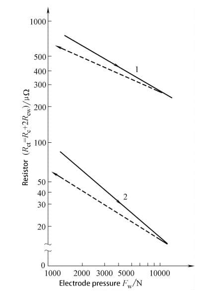
Note: Plate thickness is 1mm; 1 represents low carbon steel; 2 represents aluminum alloy.
spot welding electrode
Functions of spot welding electrodes
The spot welding electrode is a crucial component for ensuring the quality of spot welding. Its primary functions include conducting electric current to the workpiece, transmitting pressure to the workpiece, and rapidly dissipating heat from the welding zone. Common forms of spot welding electrodes are shown in Figure 1-13.

a) Standard straight electrode b) Bent electrode c) Cap electrode d) Threaded electrode e) Composite electrode
Requirements for electrode materials
Based on the aforementioned functions of the electrode, the materials used for manufacturing the electrode should possess sufficiently high electrical conductivity, thermal conductivity, and high-temperature hardness.
The electrode’s structure must have adequate strength and rigidity, as well as sufficient cooling conditions. Additionally, the contact resistance between the electrode and the workpiece should be sufficiently low to prevent surface melting of the workpiece or alloying between the electrode and the workpiece surface.
Common electrode materials
According to the provisions of the Aviation Industry Standard HB5420 1989 of the Ministry of Aerospace Industry of China, electrode materials are classified into four categories, with three categories commonly used.
(1)Category 1 materials are high electrical conductivity and medium hardness copper and copper alloys, which achieve their hardness requirements primarily through cold working. They are suitable for manufacturing electrodes for welding aluminum and aluminum alloys and can also be used for spot welding coated steel plates, although their performance is not as good as that of Category 2 alloys.
Category 1 alloys are also commonly used for manufacturing non-stressed or low-stress conductive components. Among the three categories of alloys, chromium-niobium copper, chromium-zirconium-niobium copper, and cobalt-chromium-silicon copper exhibit superior performance and have been widely used. Their respective grades are referred to as DJ70, DJ85, and DJ100, as shown in Table 1-1.
Table 1-1: Common Material Properties
| Names | Varieties | Material properties | |||
| Hardness | Electrical conductivity /(MS/m) | Softening temperature /℃ | |||
| HV30kg | HRB | ||||
| Not less than | |||||
| Chromium copper | Cold drawn bars | 85 | 53 | 56 | 150 |
| Chromium zirconium copper | Forged bars | 90 | 53 | 45 | 250 |
| Cobalt chromium silicon copper | Cold drawn bars | 183 | 90 | 26 | 600 |
In addition, there is a tungsten-copper composite sintering material, which is suitable for situations with high heat, long welding times, inadequate cooling, or high pressure.
It is used for complex electrodes for copper plate spot welding, embedded electrodes for projection welding, or wire cross welding electrodes. With an increase in tungsten content, the material’s strength and hardness increase, but both its electrical conductivity and thermal conductivity decrease.
2) The second category of materials has higher electrical conductivity and hardness compared to the first category of alloys. These alloys can achieve their performance requirements through a combination of cold working and heat treatment. Compared to the first category of alloys, they have higher mechanical performance, moderate electrical conductivity, and strong deformation resistance under moderate pressure.
Therefore, they are the most commonly used electrode materials and are widely used for spot welding low carbon steel, low alloy steel, stainless steel, high-temperature alloys, low-conductivity copper alloys, and coated steel. Category 2 alloys are also suitable for manufacturing shafts, clamps, platens, electrode holders, and various conductive components in resistance welding machines.
3) The third category of materials has lower electrical conductivity than the first and second categories, and higher hardness than category 2 alloys. These alloys can achieve their performance requirements through heat treatment or a combination of cold working and heat treatment. They have higher mechanical performance, good wear resistance, high softening temperature, and lower electrical conductivity.
Therefore, they are suitable for spot welding materials with high resistance and high temperature and strength, such as chromium zirconium copper. These metals have good electrical conductivity, thermal conductivity, high hardness, wear resistance, fracture resistance, and high softening temperature. When welded, the electrodes experience minimal wear, fast welding speeds, and low overall welding costs.
With the needs of industrial production, resistance welding has placed higher demands on electrode materials in terms of strength, softening point, and electrical conductivity in high-speed, high-paced production processes. Particle-strengthened copper-based composite materials (also known as dispersion-strengthened copper) have received attention as a new type of electrode material and are widely used.
This involves adding or using specific process measures to produce fine, dispersed second-phase particles in a copper matrix with good thermal stability. These particles can impede dislocation movement, improving the material’s room temperature strength, while also inhibiting recrystallization, thereby enhancing its high-temperature strength, such as Al2O3-Cu and TiB2-Cu composite materials.
The composition and properties of typical dispersion-strengthened copper resistance welding electrode materials are shown in Table 1-2.
Table 1-2 Composition and Performance of Typical Dispersion Strengthened Copper Resistance Welding Electrode Materials
| Mass Fraction of Material Dispersion (Mass %) | Tensile Strength /MPa | Elongation (%) | Electrical Conductivity (% IACS) | Applicable Range |
| Cu-0.38Al2O3 | 490 | 5 | 84 | Suitable for automotive manufacturing, with a lifespan 4 to 10 times that of chromium copper spot welding electrodes. |
| Cu-0.94Al2O3 | 503 | 7 | 83 | |
| Cu-0.16Zr-0.26Al2O3 | 434 | 8 | 88 | |
| Cu-0.16Zr-0.94Al2O3 | 538 | 5 | 76 |
Structure of Spot Welding Electrodes
The structure of spot welding electrodes can be divided into five types: standard straight electrodes, bent electrodes, cap electrodes, threaded electrodes, and composite electrodes.
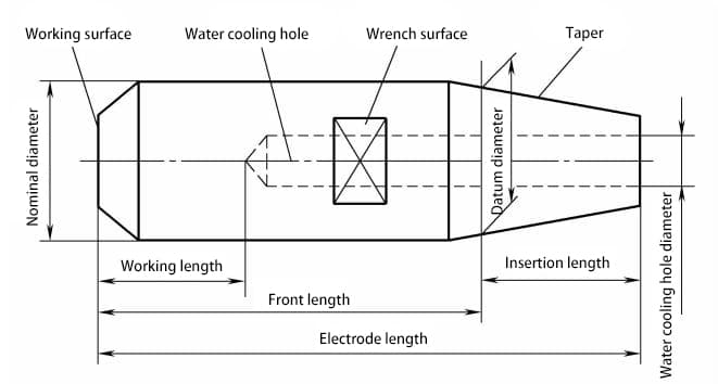
Spot welding electrodes consist of four parts: the tip, body, tail, and cooling water hole. The standard straight electrode is the most widely used type of electrode in spot welding, and the names of the electrode parts are shown in Figure 1-14.
According to the different working surfaces of spot welding electrodes, there are six types of designations and forms for standard electrodes (i.e., straight electrodes), as shown in Figure 1-15.
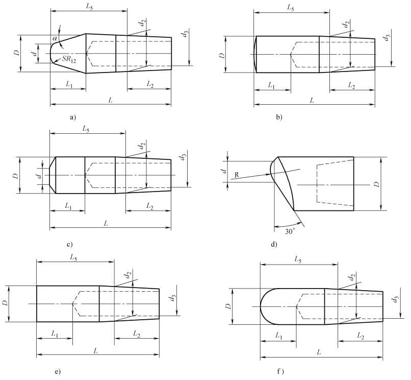
a) Pointed electrode (code J)
b) Spherical electrode (code H)
c) Conical electrode (code Y)
d) Offset wedge-shaped electrode (code EF)
e) Flat electrode (code M)
f) Spherical cap electrode (code Q)
The electrode tip directly contacts the high-temperature workpiece surface and repeatedly withstands high temperatures and pressures during welding production. Therefore, adhesion, alloying, and deformation are the key considerations in electrode design.
Main Parameters of Spot Welding Electrodes
1) Key Physical Parameters: Hardness greater than 75 HRB, electrical conductivity greater than 75% IACS, softening temperature of 550°C, as shown in Table 1-3.
2) Key Chemical Composition as shown in Table 1-4.
Table 1-3: Key Physical Parameters
| Density (g/cm3) | Tensile Strength (N/mm²) | Hardness HV | Elongation (%) | Electrical Conductivity (20°C) IACS (%) | Thermal Conductivity (20°C) (W/m·K) |
| 8.9 | ≥380 | 110~145 | ≥15 | ≥75 | 330 |
Table 1-4: Key Chemical Composition
| Name | Al | Mg | Cr | Zr | Fe | Si | P | Total Impurities |
| Chromium Zirconium Copper | 0. 1 ~ 0. 25 | 0. 1 ~ 0. 25 | 0. 1 ~ 0. 8 | 0. 3 ~ 0. 6 | 0. 5 | 0. 5 | 0. 1 | 0.5 |
Quality requirements for spot welding electrodes
1) Electrical conductivity measured using an eddy current conductivity meter, with the average of three points being greater than or equal to 44 MS/m.
2) Hardness measured using Rockwell hardness standards, with the average of three points being greater than or equal to 78 HRB.
3) In the softening temperature experiment, after maintaining a furnace temperature of 550°C for 2 hours, quenching in water should not result in a reduction of hardness by more than 15%.
Resistance welding electrodes generally employ a combination of heat treatment and cold working to ensure performance. This approach yields optimal mechanical and physical properties. Chromium zirconium copper is used as a general-purpose resistance welding electrode, primarily for spot welding or seam welding low carbon steel and plated steel plates.
It can also be used as electrode holders, shafts, and liner materials when welding low carbon steel, or as large molds, fixtures for projection welding machines, and electrodes for stainless steel and heat-resistant steel.

