Comprehensive Guide to Mastering Spot Welding for Beginners
Have you ever marveled at the seamless joints in metal structures and wondered how they were made? Spot welding, a…

In terms of welding processes, the most widely used welding robots currently include arc welding, spot welding, and laser welding robots. Spot welding robot refers to an industrial robot used for automated spot welding operations, or can be interpreted as a type of industrial robot equipped with spot welding tongs.
Using the example of the 6-axis Yaskawa spot welding robot with a payload of 165kg, the robot’s outer appearance is as shown in Figure 2-1 (refer to the accompanying CD video – (1) Robot Production Process).
Since in practical use, the robot is almost entirely used to perform spot welding operations at intervals of 30-50mm, it rarely reaches its maximum speed during movement. Therefore, improving the performance of frequent short-duration torque starts and stops in the shortest time possible is a key focus for the robot.
In order to increase acceleration and deceleration, the weight of the arm has been reduced in the design, and the output torque of the drive system has been increased. At the same time, in order to reduce the lag time and achieve high static positioning accuracy, this model uses low inertia, high rigidity reducers, and high-power brushless servo motors.
As measures such as feedforward compensation and state observers are adopted in the control circuit, the control performance has been greatly improved, and the positioning time for a 50mm short-distance movement has been reduced to within 0.4 seconds. The technical specifications of the commonly used MOTOMAN ES165D articulated spot welding robot main body are listed in Table 2-1.
The spot welding robot control system consists of the main body control section and the welding control section. The main body control section mainly consists of a teaching pendant, control cabinet, and robot arm.
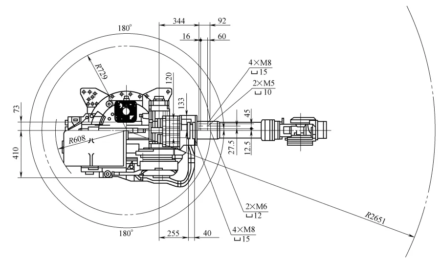
In addition to welding clamp pressure time and program switching, the welding control section controls the welding current by changing the conduction angle of the main circuit thyristor. The YRES0165DA00 arm motion range of the robot main body is shown in the top view in Figure 2-2.
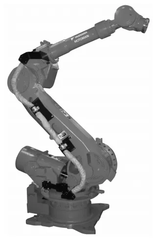
Table 2-1: Technical Specifications of the MOTOMAN-ES165D Articulated Spot Welding Robot
| Name | MOTOMAN ES165D | |
| Type | YR-ES0165DA00 | |
| Structure | Vertical Multi-joint Type (6 degrees of freedom) | |
| Payload | 165kg (151.5kg) * 3 | |
| Repeatability *1 | ±0.2mm | |
| Range of Motion | S-axis (rotation) | -180°~+180° |
| L-axis (lower arm) | -60°~+76° | |
| U-axis (upper arm) | -142.5°~+230° | |
| R-axis (wrist rotation) | -360°~+360°(-205°~+205°)*3 | |
| B-axis (wrist swing) | -130°~+130°(-120°~+120°)*3 | |
| T-axis (wrist twist) | -360°~+360°(-180°~+180°)*3 | |
| Maximum Speed | S-axis (rotation) | 1.92rad/s,110°/s |
| L-axis (lower arm) | 1.92rad/s,110°/s | |
| U-axis (upper arm) | 1.92rad/s,110°/s | |
| R-axis (wrist rotation) | 3.05rad/s,175°/s | |
| B-axis (wrist swing) | 2.62rad/s,150°/s | |
| T-axis (wrist twist) | 4.19rad/s,240°/s | |
| Permissible Moment of Inertia (GD²/4) | R-axis (wrist rotation) | 921N m(868N m)*3 |
| B-axis (wrist swing) | 921N m( 868N m)*3 | |
| T-axis (wrist twist) | 490N m | |
| Permissible Inertial Moment | R-axis (wrist rotation) | 85kg · m²(83kg · m²) *3 |
| B-axis (wrist swing) | 85kg m²(83kg m²)*3 | |
| T-axis (wrist twist) | 45kg · m2 | |
| Weight of the Robot | 1100KG | |
| Installation Environment | Temperature | 0° to +45° |
| Humidity | 20% to 80% RH (non-condensing) | |
| Vibration | Below 4.9m/s2 | |
| Others | 1.Keep away from corrosive gases or liquids, flammable gases 2.Keep the environment away from water, oil, and dust 3.Keep away from electrical noise sources | |
| Power Capacity *2 | 5.0kV A | |
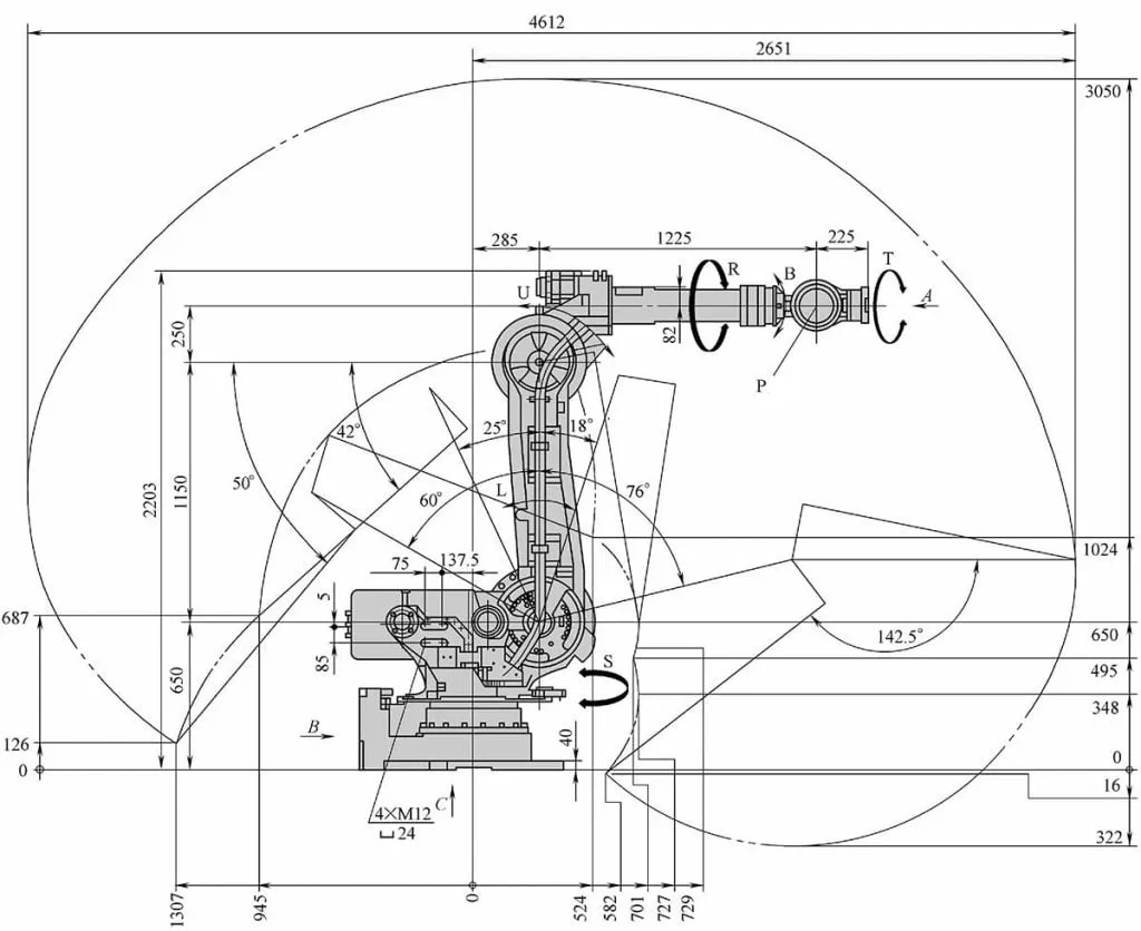
The side view of the arm motion range of the robot body YRES0165DA00 is shown in Figure 2-3.
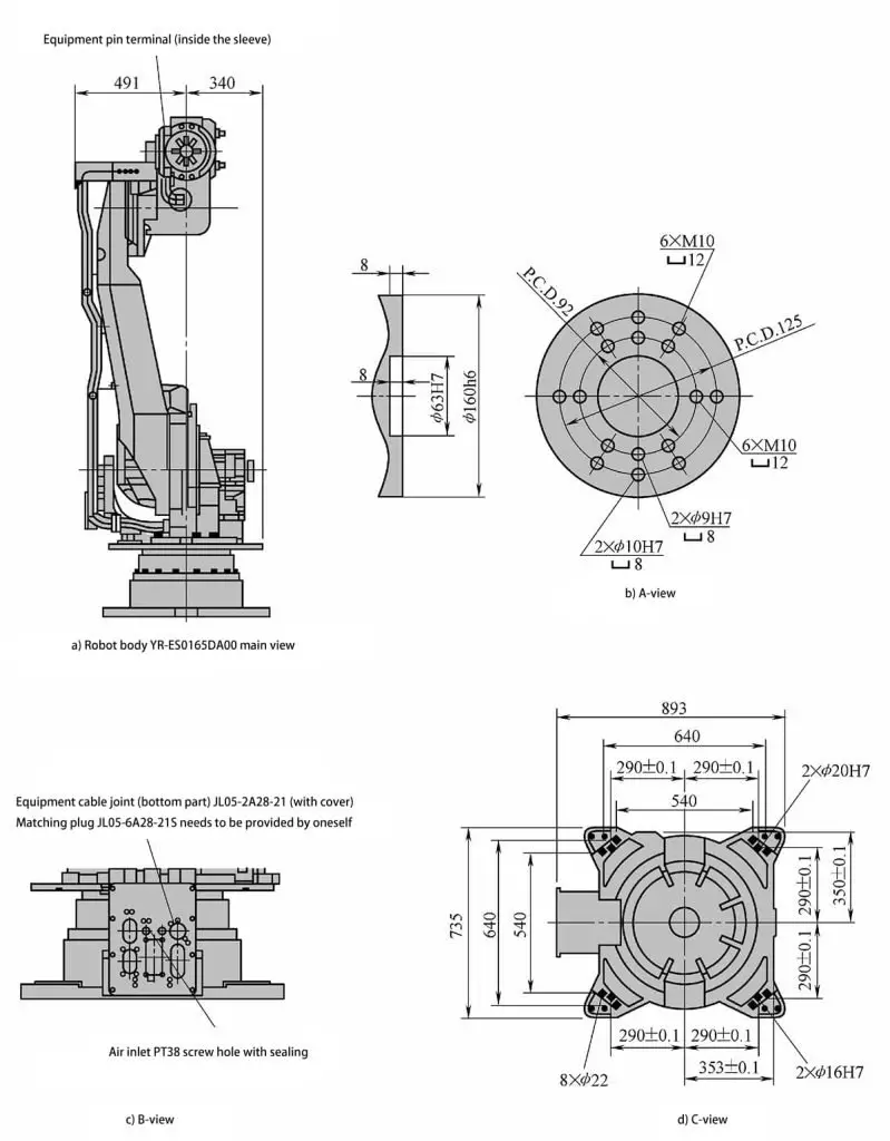
The front view of the robot body YRES0165DA00 and the partial views of the A, B, and C directions are shown in Figure 2-4.
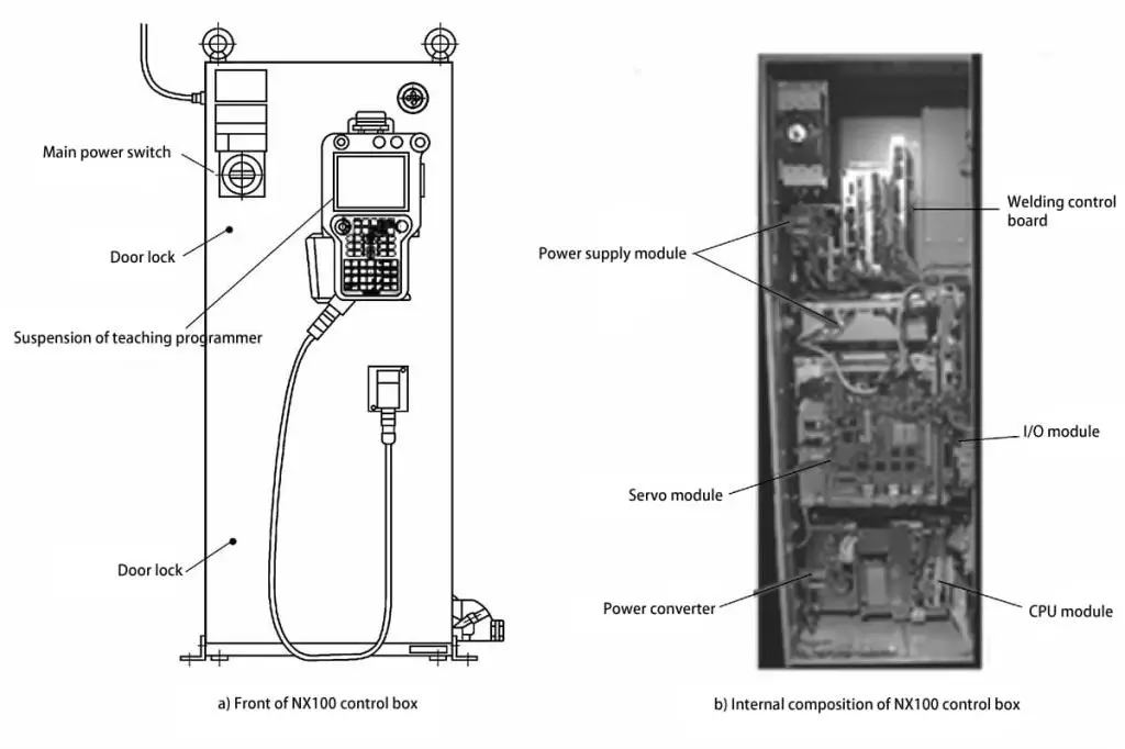
The front and internal structure of the NX100 robot control cabinet are shown in Figure 2-5.
In Figure 2-5, the power supply module includes the main power supply unit; the welding command board includes the I/F unit welding database and program storage; the servo module comprises the servo operation amplification drive circuit; the power converter provides power to the control cabinet units; the I/O module contains input/output circuits and interfaces; the CPU module includes the control board, backplane, timing control board, and control power supply.
When opening the control cabinet door, the switch handle must be set to OFF. Then, use a slotted screwdriver to turn the door lock (there are two locks on the door – clockwise to unlock, counterclockwise to lock). While opening the door, hold the door and use the slotted screwdriver to turn the door lock. After closing the door, upon hearing a “click” sound, the door is locked securely.
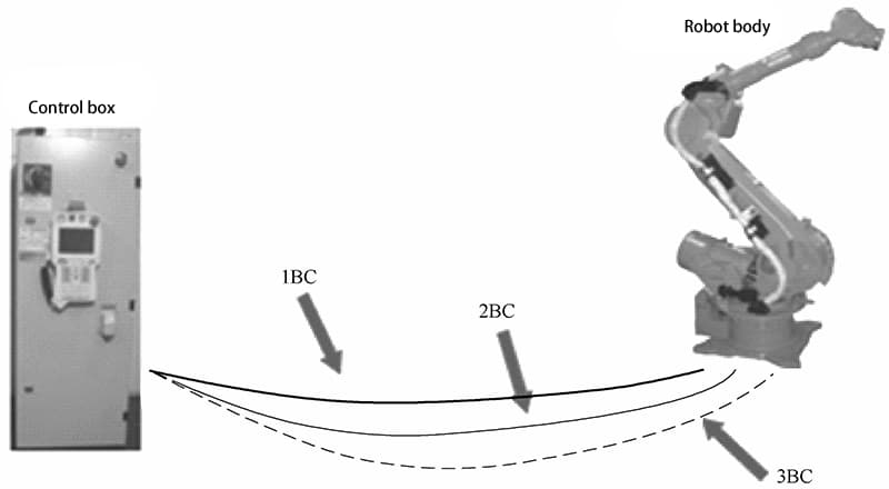
The welding robot body is connected to the control box via 1BC, 2BC, and 3BC cables to transmit encoder feedback signals and robot servo motor drive signals, as shown in Figure 2-6.
In comparison to arc welding robots, spot welding imposes less stringent demands on the robot used. This is because spot welding only requires point-to-point control, and there are no strict requirements for the movement trajectory of the welding tongs between points.
This is also the reason why robots were initially only used for spot welding. Spot welding robots not only require sufficient load capacity, but also need to move quickly and smoothly between points, with precise positioning, in order to reduce displacement time and improve work efficiency.
The required load for spot welding robots depends on the type of welding tongs used. For welding tongs used for transformer separation, a load of 30.5kg is sufficient. However, these tongs are limited by the length of the main secondary cable, leading to energy loss and making it difficult for the robot to extend the tongs for internal welding of workpieces.
Additionally, the cable constantly swings with the robot’s movement, leading to rapid cable damage. Therefore, modern applications often use integrated welding tongs, with the weight of these tongs typically around 10kg.
Considering that the robot needs sufficient load capacity to quickly move the welding tongs to spatial positions for welding, heavy-duty robots with a load capacity of 100 to 165kg are generally selected.
To meet the requirement of rapid short-distance movement of the welding tongs during continuous spot welding, new heavy-duty robots have been equipped with the capability to complete a 50mm displacement within 0.3 seconds. This places higher demands on motor performance, microcomputer processing speed, and algorithms.
Therefore, spot welding robots should have stable performance, a large range of motion, fast movement speed, and strong load capacity. The welding quality should be significantly superior, contributing to improved productivity in spot welding operations.
Spot welding robots are equipped with interfaces for communication with external devices, allowing them to receive control commands from higher-level controllers and management computers. Therefore, under the control of the main computer, multiple spot welding robots can be configured to form a flexible spot welding production system.
As the executive tool of the robot, spot welding tongs impose significant constraints on the robot’s use. If the selection is not reasonable, it will directly affect the robot’s operational efficiency and accessibility, posing a significant threat to the safety of robot operations.
The design of spot welding robot tongs must meet production and operational requirements based on production needs and operational characteristics. Due to the many differences between robot operations and traditional manual operations, there are significant contrasts between the two, as shown in Table 2-2.
Table 2-2: Characteristics Comparison between Manual Operation Spot Welding Gun and Robotic Spot Welding Gun
| Manual Operation Spot Welding Gun | Robotic Spot Welding Gun |
| Not very strict on the weight of the spot welding gun | The spot welding gun is mounted on the robot, and each robot has a rated load, thus strict requirements for the weight of the spot welding gun |
| Relies heavily on human intelligence to handle various issues | Operates strictly according to the program, with the ability to handle issues such as different positions of workpieces and samples, therefore the welding gun must have automatic compensation function to achieve automatic tracking of work |
| Does not require consideration of the relative position between the welding gun and the operator | During the robot’s movement, rotation, positioning, and return processes, in order to prevent collisions with workpieces or other devices, the spot welding gun must be in a fixed position while moving, hence the need for a limit mechanism in the design of the spot welding gun |
| The actions of the spot welding gun are controlled by a person and do not require signal consideration | The robotic spot welding gun operates according to the program, and a command needs to be issued at the end of each action, therefore, the spot welding gun needs to be controlled by signals |
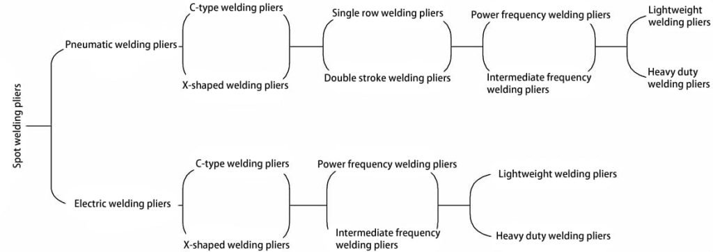
(1) According to the structural form, spot welding guns can be divided into C-type welding guns and X-type welding guns.
(2) According to the stroke of the spot welding gun, it can be categorized as single-stroke and double-stroke.
(3) Based on the pressurization driving method, spot welding guns can be classified into pneumatic welding guns and electric welding guns.
(4) According to the type of spot welding gun transformer, they can be categorized into industrial frequency welding guns and medium frequency welding guns.
(5) According to the magnitude of the pressurization force of the spot welding gun, it can be divided into light-duty welding guns and heavy-duty welding guns. Generally, spot welding guns with electrode pressure above 450kg are referred to as heavy-duty welding guns, while those below 450kg are referred to as light-duty welding guns.
In summary, the classification of spot welding guns is shown in Figure 2-7.
1) C-type Welding Electrode
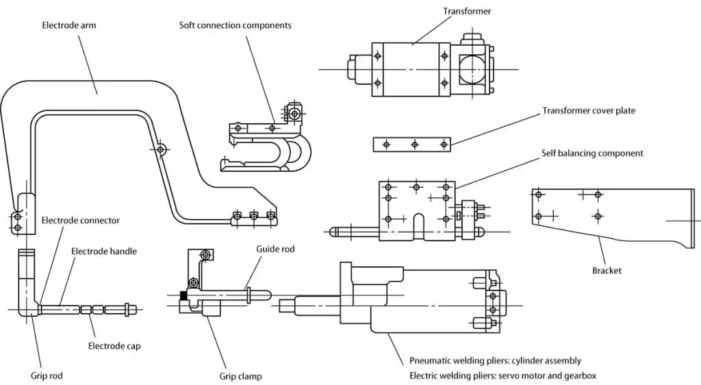
Depending on the welding position, the C-type welding electrode is mainly used for spot welding in vertical and near-vertical inclined positions. The structure and component names of the C-type welding electrode are shown in Figure 2-8.
(2) X-Type Welding Electrode
The X-type welding electrode is primarily used for spot welding in horizontal and near-horizontal inclined positions. The structure and component names of the X-type welding electrode are shown in Figure 2-9.
The general structural form of spot welding electrodes requires special design of the electrode body based on the specific characteristics of the spot welding positions in practical applications. Only in this way can the welding electrode reach the welding point position.
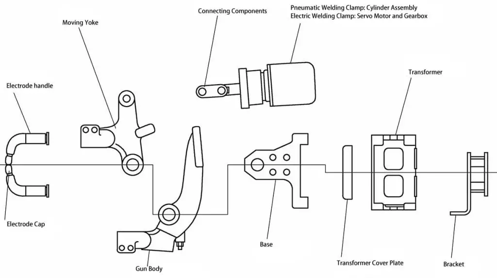
Figure 2-9 Structure and Component Names of X-Type Welding Electrode
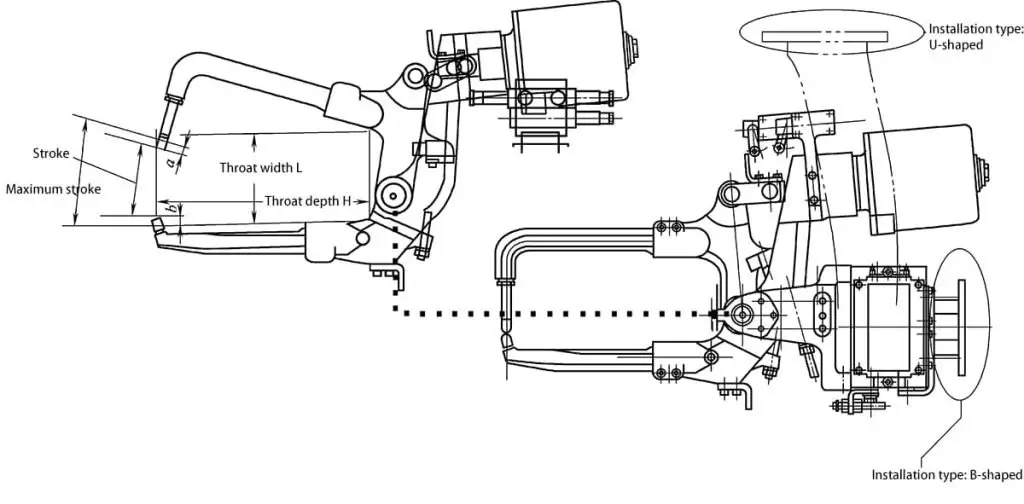
1) The schematic diagram of the structure of the C-type pneumatic welding electrode is shown in Figure 2-10.
2) The selection parameters for the C-type pneumatic welding electrode are listed in Table 2-3.
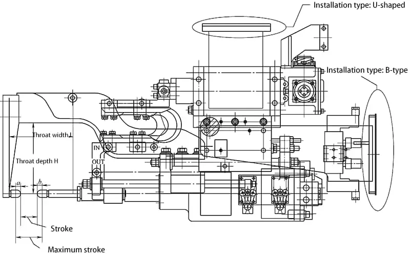
Note: a and b represent the stroke requirements caused by the electrodes. The maximum stroke includes not only a + b but also the increased demand caused by the deflection of the electrode handle.
Table 2-3 Selection Parameters of C-Type Pneumatic Welding Electrode
| Basic Technical Specifications | Content | The robots MOTOMAN-ES165D, MOTOMAN-ES200D, MOTOMAN-ES165RD, and MOTOMAN-ES200RD are compatible with two types of welding clamp flanges: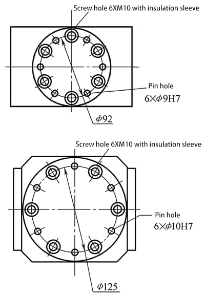 | |
| Type of Welding Clamp | Pneumatic C-type Welding Clamp | ||
| Welding Clamp Body | Throat Depth H/mm | ||
| Throat Width H/mm | |||
| Stroke /mm | |||
| Maximum Stroke /mm | |||
| Maximum Clamping Force /kgf | |||
| Transformer | Type (Line frequency or medium frequency) | ||
| Capacity/kVA | |||
| Maximum Current | |||
| Clamp Stroke Type | Single Stroke | ||
| Dual Stroke | |||
| *Note: If using a dual-stroke welding clamp, small opening stroke /mm | |||
| Mounting Configuration of the Welding Clamp on the Robot | |||
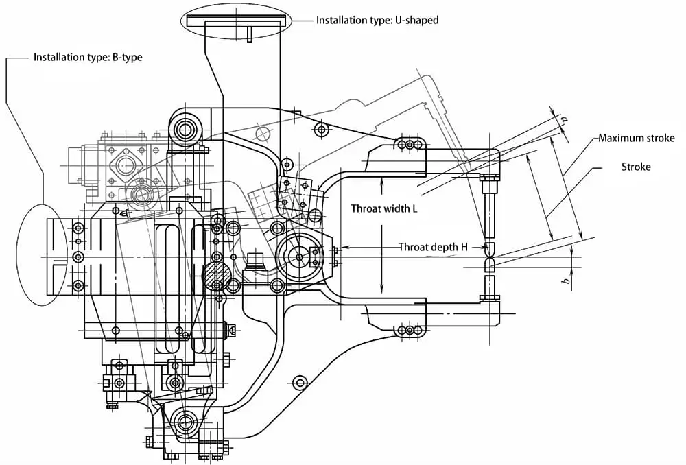
1) The schematic diagram of the C-Type Electric Welding Clamp structure is shown in Figure 2-11.
2) Refer to Table 2-4 for the selection parameters of the C-Type Electric Welding Clamp.
Note: a and b represent the stroke requirements caused by the electrode, the maximum stroke includes the demand increase caused by the flexure of the electrode holder in addition to a+b.
Table 2-4 Selection Parameters for C-Type Electric Welding Clamp
| Basic Technical Specifications | Content | The robots MOTOMAN-ES165D, MOTOMAN-ES200D, MOTOMAN-ES165RD, and MOTOMAN-ES200RD are compatible with two types of welding clamp flanges: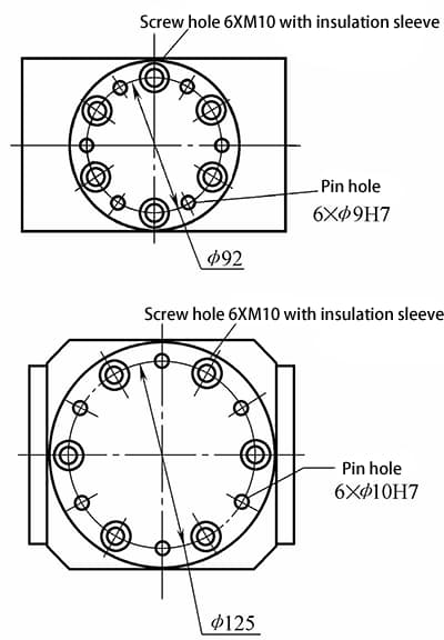 | |
| Type of Welding Clamp | C-Type Servo Welding Clamp | ||
| Welding Clamp Body | Throat Depth H/mm | ||
| Throat Width H/mm | |||
| Stroke /mm | |||
| Maximum Stroke /mm | |||
| Maximum Clamping Force /kgf | |||
| Transformer | Type (Line frequency or medium frequency) | ||
| Capacity/kVA | |||
| Maximum Current | |||
| Servo Motor Model Number | |||
| Mounting Configuration of the Welding Clamp on the Robot | |||
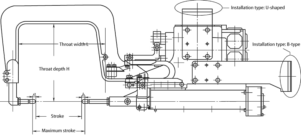
1) The schematic diagram of the X-type pneumatic welding clamp is shown in Figure 2-12.
2) The selection parameters for the X-type pneumatic welding clamp are listed in Table 2-5.
Note: “a” and “b” represent the stroke requirements caused by the electrodes, and the maximum stroke includes the demand caused by the deflection of the electrode holder in addition to “a” and “b”.
Table 2-5: Selection parameters for the X-type pneumatic welding clamp
| Basic Technical Specifications | Content | The MOTOMAN-ES165D, MOTOMAN-ES200D, MOTOMAN-ES165RD, and MOTOMAN-ES200RD robot bodies are compatible with two types of welding torch flanges.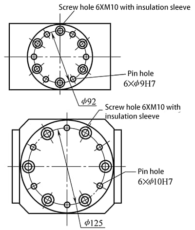 | |
| Type of Welding Clamp | X-type pneumatic welding clamp | ||
| Welding Clamp Body | Throat Depth H/mm | ||
| Throat Width H/mm | |||
| Stroke /mm | |||
| Maximum Stroke /mm | |||
| Maximum Clamping Force /kgf | |||
| Transformer | Type (Line frequency or medium frequency) | ||
| Capacity/kVA | |||
| Maximum Current | |||
| Clamp Stroke Type | |||
| *Note: If using a dual-stroke welding clamp, small opening stroke /mm | |||
| Mounting Configuration of the Welding Clamp on the Robot | |||
1) The schematic diagram of the X-type electric welding clamp is shown in Figure 2-13.
2) The selection parameters for the X-type electric welding clamp are listed in Table 2-6.
Note: “a” and “b” represent the stroke requirements caused by the electrodes, and the maximum stroke includes the demand caused by the deflection of the electrode holder in addition to “a” and “b”.‘’
Table 2-6: Selection parameters for the X-type electric welding clamp
| Basic Technical Specifications | Content | The MOTOMAN-ES165D, MOTOMAN-ES200D, MOTOMAN-ES165RD, and MOTOMAN-ES200RD robot bodies are compatible with two types of welding torch flanges.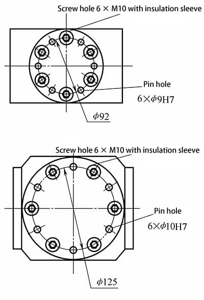 | |
| Type of Welding Clamp | X-type servo welding clamp | ||
| Welding Clamp Body | Throat Depth H/mm | ||
| Throat Width H/mm | |||
| Stroke /mm | |||
| Maximum Stroke /mm | |||
| Maximum Clamping Force /kgf | |||
| Transformer | Type (Line frequency or medium frequency) | ||
| Capacity/kVA | |||
| Maximum Current | |||
| Servo Motor Model Number | |||
| Mounting Configuration of the Welding Clamp on the Robot | |||
The physical illustrations of the X-type pneumatic welding clamp and the C-type pneumatic welding clamp are shown in Figure 2-14 above.
Whether it’s a manual suspension spot welding clamp or a robotic spot welding clamp, there are specific requirements in the ordering process. It must conform to the welding specifications required by the workpiece. The basic principles are as follows:
1) Determine the maximum short-circuit current and maximum pressure of the welding clamp electrodes based on the workpiece and material thickness.
2) Based on the shape of the workpiece and the position of the weld points on the workpiece, determine the throat depth, throat width, electrode holder, maximum stroke, working stroke, etc., of the welding clamp body.
3) Based on the distribution of all weld points on the workpiece, determine the type of welding clamp. There are typically four common types of welding clamps: single-action C-type welding clamp, double-action C-type welding clamp, single-action X-type welding clamp, and double-action X-type welding clamp.
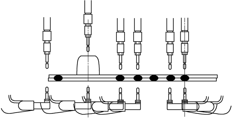
Under the above conditions, it is important to minimize the weight of the welding clamp as much as possible. For suspension spot welding, this can reduce the labor intensity of the operators. For robotic spot welding, it is possible to select a low-load robot, thereby improving production efficiency. Depending on the size and welding position of the workpiece, select large-gap welding clamps and small-gap welding clamps, as shown in Figure 2-15.
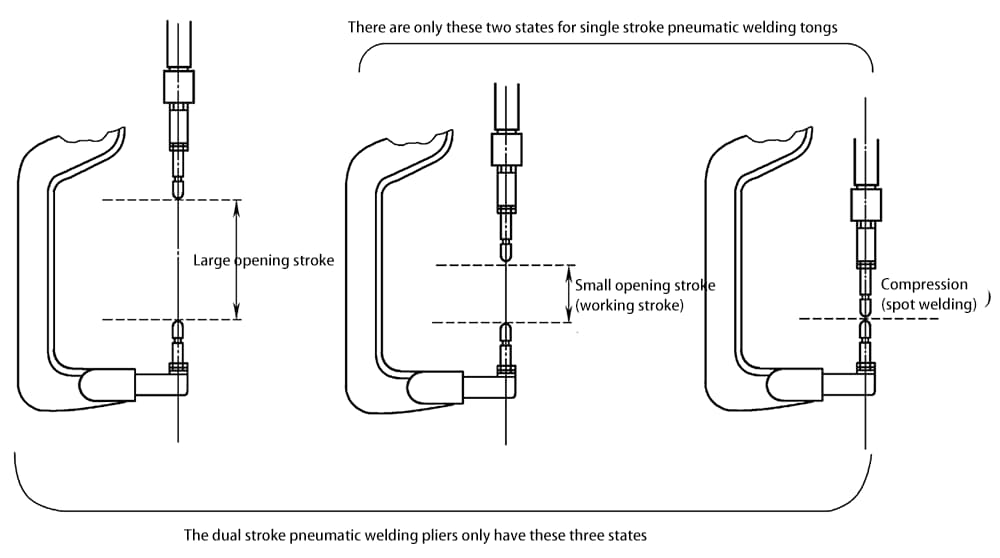
Choose single-action pneumatic welding clamps and double-action pneumatic welding clamps according to the process requirements, as shown in Figure 2-16.
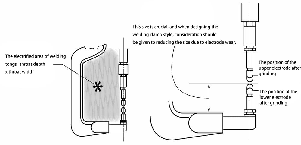
The energized area of the welding clamp = throat depth × throat width. The larger this area, the stronger the inductance generated during welding, making current output more difficult. In such cases, it is typical to use a higher power transformer or employ an inverter transformer for current output. Select the size of the welding clamp based on electrode wear, as shown in Figure 2-17.
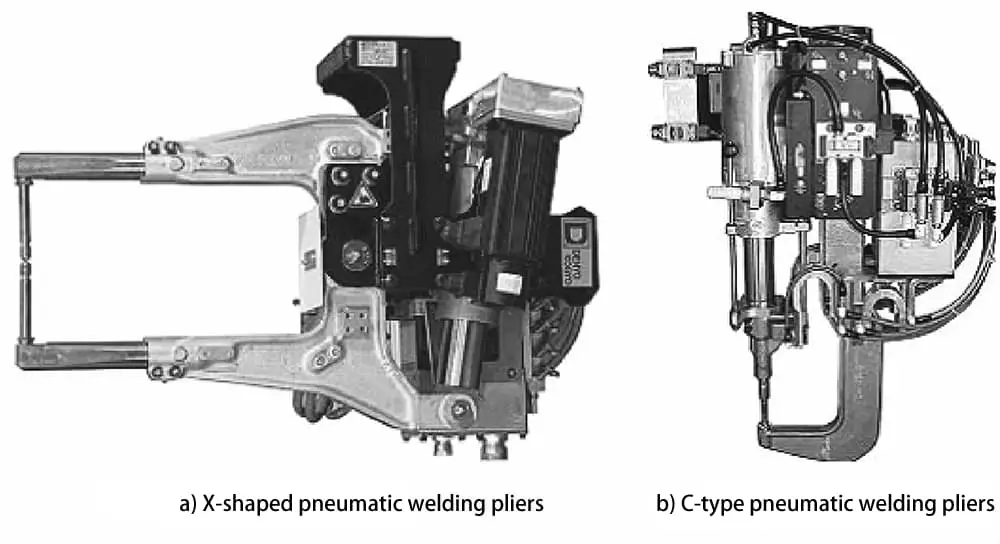
a) X-type pneumatic welding tongs
b) C-type pneumatic welding tongs
Spot welding robots typically consist of the robot body, robot control device, teach pendant, spot welding tongs, and welding system, as shown in Figure 2-18.The names of each component in Figure 2-18 are listed in Table 2-7.
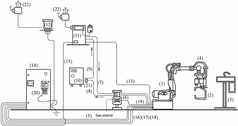
Table 2-7 Names of Various Components in Spot Welding Robot System
| Number | Name | Number | Name |
| 1 | Robot Body (ES165D/ES200D)★ | 12 | Robot Transformer★ |
| 2 | Servo/Pneumatic Spot Welding Tongs | 13 | Tongs Power Supply Cable☆ |
| 3 | Electrode Grinding Machine | 14 | Robot Control Cabinet (DX100)★ |
| 4 | Wrist Unit Cable (GISO) | 15 | Spot Welding Instruction Cable (I/F)◇ |
| 5 | Tongs (Pneumatic/Servo) Control Cable SI | 16 | Robot Power Supply Cable 2BC★ |
| 6 | Air/Water Pipe Assembly☆ | 17 | Robot Power Supply Cable 3BC★ |
| 7 | Tongs Cooling Water Pipe◇ | 18 | Robot Control Cable 1BC★ |
| 8 | Tongs Return Water Pipe◇ | 19 | Tongs Inlet Air Pipe☆ |
| 9 | Spot Welding Control Box Cooling Water Pipe | 20 | Robot Teach Pendant (PP)★ |
| 10 | Chiller☆ | 21 | Cooling Water Flow Switch☆ |
| 11 | Spot Welding Control Box◇ | 22 | Power Supply |
The functions of each component of the spot welding robot system are classified in Table 2-8.
Table 2-8: Classification of Functions for Each Component of the Spot Welding Robot System
| Category | Equipment Codes (Refer to Figure 2-18) | Function Description |
| Robot-related | (1), (4), (5), (13), (14), (15), (16), (17), (18), (20) | Establishes the connection between the robot and other equipment, introduced by Yaskawa from Japan |
| Spot welding-related | (2), (3), (11) | Implements spot welding conditions, provided by the spot welding equipment manufacturer |
| Gas supply system | (6), (19) | Used only when using pneumatic welding tongs, the welding tongs’ pressure cylinder completes the spot welding pressure, provided by the system designer |
| Water supply system | (7), (8), (9), (10), (21) | Used for cooling equipment (2) and (11), provided by the system designer |
| Power supply system | (12), (22) | System power |
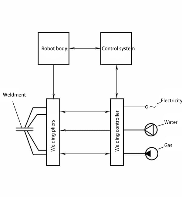
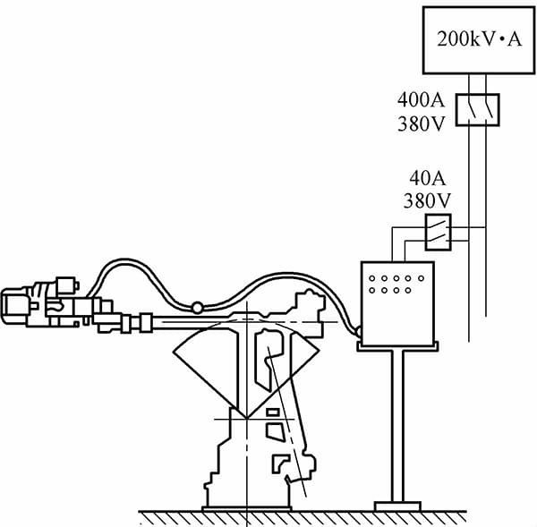
The welding system mainly consists of the welding controller (timer), welding tongs (including the resistance welding transformer), and auxiliary parts such as water, electricity, and gas. The system composition and principles are shown in Figure 2-19.
From the structural relationship between the resistance welding transformer and the welding tongs, the welding tongs can be divided into three forms: separate, embedded, and integral.
(1) Separate Welding Tongs
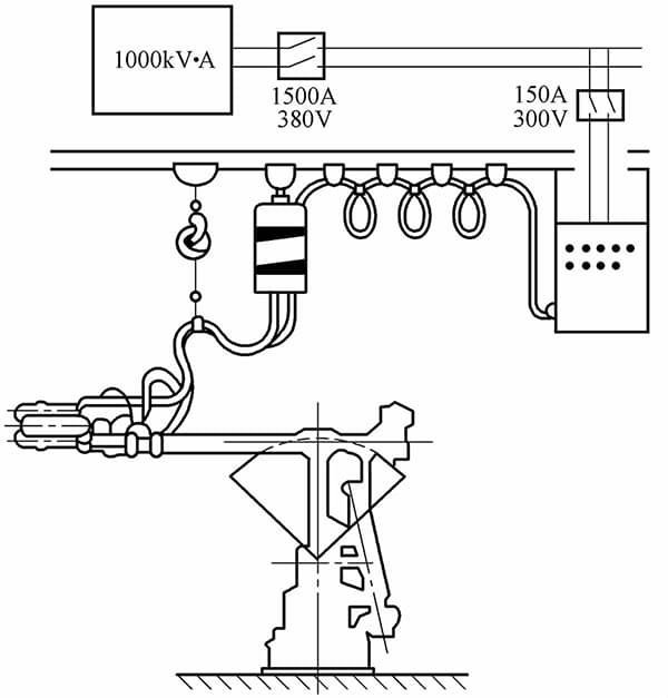
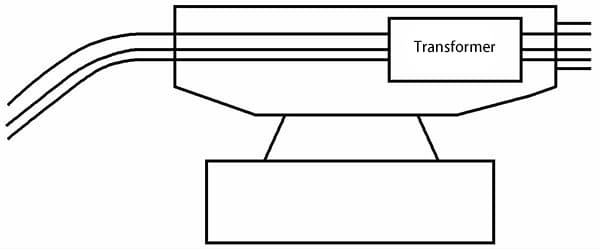
The characteristic of these tongs is that the resistance welding transformer is separate from the tong body. The tong body is mounted on the robot arm, while the welding transformer is suspended above the robot and can move along the direction of the robot’s wrist on a track. The two are connected by a secondary cable. The advantages include reducing the robot’s load, high movement speed, and lower cost, as shown in Figure 2-20.
The main drawback of separate welding tongs is the need for a large-capacity welding transformer, resulting in higher power consumption and lower energy efficiency. Additionally, the large secondary cable causes tensile and torsional forces on the robot’s arm, limiting the selection of spot welding work areas and positions. Separate welding tongs can use regular suspended welding tongs and resistance welding transformers.
However, the secondary cable requires special manufacturing, typically consisting of two conductors separated by an insulating layer, with each conductor being hollow for water cooling. Furthermore, the cable needs to have a certain flexibility.
(2) Embedded Welding Tongs
In this structure, the resistance welding transformer is placed inside the robot arm as close to the tong body as possible. The secondary cable of the transformer can move internally. When using this form of welding tongs, it must be designed in conjunction with the robot body. Additionally, polar or spherical coordinate spot welding robots can also adopt this structure.
The advantage is that the secondary cable is shorter, and the capacity of the transformer can be reduced, but it complicates the design of the robot body. Embedded welding tong spot welding robots are shown in Figure 2-21.
(3) Integral Welding Tongs
The so-called integral welding tongs involve mounting the resistance welding transformer and the tong body together, then fixing them together on the flange at the end of the robot arm. The main advantages include eliminating the bulky secondary cable and the work frame for the suspended transformer. The output end of the welding transformer is directly connected to the upper and lower arms of the welding tongs, saving energy.
For example, with an output current of 12000A, a separate welding tong requires a 75kVA transformer, while an integral welding tong only requires 25kVA. The main drawback of integral welding tongs is the significant increase in weight and size, requiring the robot body to bear a load greater than 60kg.
Additionally, the inertial force generated by the weight of the welding tongs on the robot’s active wrist can cause overload, requiring the center of gravity of the welding tongs to be as close as possible to the axis of the robot’s arm during design. The design of the resistance welding transformer is the main issue for integral welding tongs.
Because the transformer is confined to the small space of the welding tongs, the dimensions and weight must be smaller than usual, and the secondary coil also needs water cooling.
Currently, small integrated resistance welding transformers manufactured using vacuum epoxy casting processes are used. For example, a 30kVA transformer has dimensions of 325×135×125mm³ and weighs only 18kg. Integral welding tong spot welding robots are shown in Figure 2-22.
The working principle of the welding (spot welding) controller is to detect the secondary current and voltage input to the workpiece being welded, as well as the corresponding impedance change value obtained from the metal melting state of the workpiece.
This information is then fed back to the robot controller for calculation, outputting the most suitable welding current and storing the welding current for each spot to provide reference for setting welding parameters for subsequent spots. This type of resistance welding controller can ensure welding quality by controlling the splashing during the welding process, and it can also automatically manage the front-end size of the electrode.
According to the predetermined welding monitoring program, the controller completes the input of welding parameters during spot welding, controls the spot welding program, controls the welding current, diagnoses welding system faults, and establishes communication with the main computer and the teach pendant. The commonly used spot welding controllers mainly have the following three structural forms.
(1) Centralized Structure Type
In this type, the welding control part is arranged as a module in the same control cabinet as the robot’s main control part and is managed collectively by the main computer, providing data to the welding module, with the welding process control being completed by the welding module. The advantage of this structure is its high integration and ease of unified management.
(2) Decentralized Structure Type
The decentralized structure type separates the welding controller from the robot’s main control cabinet, and the two communicate using a response-type communication. After the main computer provides the welding signal, the welding control is independently controlled by the welding controller, and after the welding is completed, an end signal is sent to the main computer to control the robot’s movement.
The advantage of this structure is its flexible debugging, and the welding system can be used independently, but it requires communication over a certain distance, and its integration is not as high as the centralized structure type. The welding cycle of the decentralized structure type is shown in Figure 2-23.
(3) Group Control System
The group control system connects multiple spot welding robots (or conventional welding machines) to a group control computer to control several devices that are simultaneously powered, achieving time-sharing control of the welding current of multiple spot welding robots, limiting the instantaneous load of the power grid, and stabilizing the grid voltage to ensure welding quality.
The group control system can significantly reduce the capacity of the workshop’s power supply transformer. In addition, when a robot (or spot welding machine) experiences a fault, the group control system starts a backup spot welding robot or reallocates work to the remaining robots to ensure normal welding production.
To meet the needs of group control, the spot welding robot welding system should add “welding request” and “welding permission” signals and connect with the group control computer.
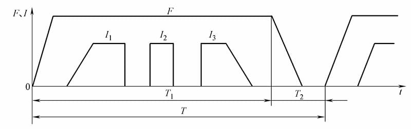
Note: T1 controls the welding controller; T2 is controlled by the robot’s main computer; T represents the welding cycle; F represents electrode pressure; I represents welding current.
1) Special welding tongs with a floating pressure device should be used, and ordinary welding tongs can also be modified. The welding tongs should be lightweight and have two types of strokes, long and short, to facilitate rapid welding, dressing, electrode replacement, and overcoming obstacles.
2) The center of gravity of the body-type welding tongs should be designed on the axis of the fixed flange.
3) The welding control system should be able to self-diagnose and self-protect against faults such as overheat of the resistance welding transformer, overheat of the thyristor causing short-circuit or open-circuit, loss of air network voltage, excessive grid voltage, and electrode sticking. In addition to notifying the host to stop, it should also display the type of fault.
4) The control system of the dispersed structure type should have communication interface to identify various signals from the robot body and teach pendant and respond accordingly.
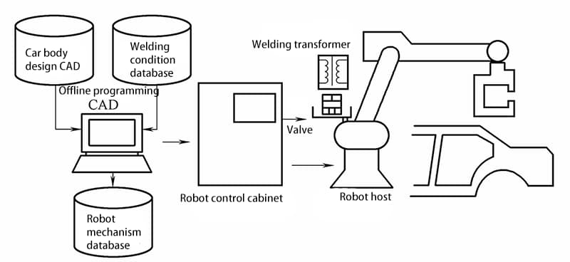
If the spot welding robot can communicate with a CAD system, offline teaching can be performed. The basic configuration of the offline teaching system for spot welding robots with CAD and welding database systems is shown in Figure 2-24.
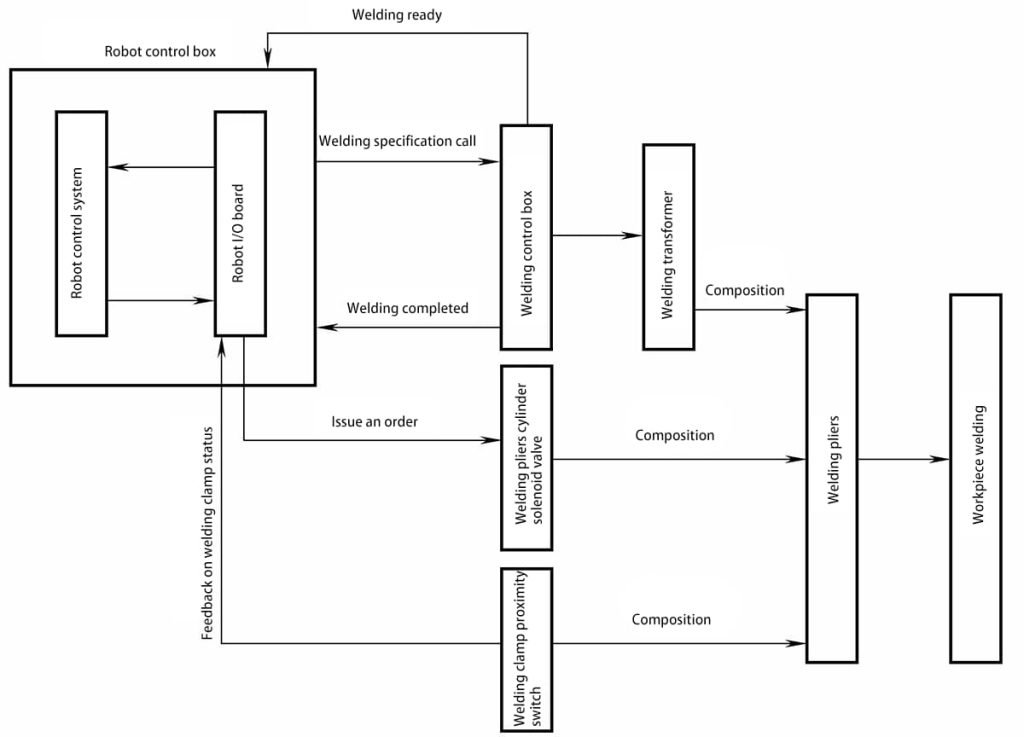
When the spot welding robot is operational, the main control system confirms the robot’s taught position. It then issues a command to close the welding tongs via the OUTPUT port on the robot’s I/O board. The solenoid valve coil for the cylinder is energized with 24V DC, initiating action. Compressed air is introduced into the cylinder, causing the piston rod to displace.
The cylinder’s displacement information is primarily provided by a position proximity switch for effective feedback. This information is relayed back to the main control system of the robot, which subsequently sends a welding command to the welding control box through the robot’s I/O board. The welding control box sends a ready-to-weld signal back to the robot’s I/O board, which is then fed back to the main control system.
The main control system issues a standard number call command, utilizing the 8421 code, which corresponds to 16 standards. The welding control box activates the pre-stored standard code, outputting the required welding time and current for the welding process. Upon completion of the welding, the welding control box sends a signal indicating the end of the welding process.
After the main control system of the robot confirms this signal, it sends a command to open the welding tongs through the OUTPUT port of the I/O board. The solenoid valve of the cylinder is de-energized, the valve core resets, the cylinder intakes air in reverse, and the tongs’ open position is locked by a proximity switch installed on the cylinder.
This information is fed back to the main control system of the robot, which then sends movement information to the robot’s motion system, as shown in Figure 2-25.
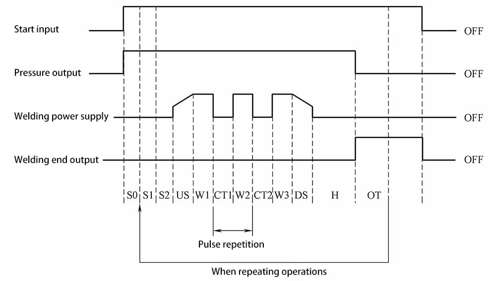
The welding tong transformer supplies current to the welding tong electrodes for the spot welding process, while the spot welding controller (also known as a “timer”) is a device that controls the duration of each phase of the spot welding process, typically set by frequency.
For instance, the PH5-7003 model spot welding controller features thyristor synchronous phase control and offers constant current control based on welding current feedback, current step-up function, various monitoring and alarm features.
It can complete the input of welding parameters, control of the spot welding program, control of the welding current, and self-diagnosis of welding system faults according to a predetermined welding monitoring program.
The main signals connecting the welding controller with the body and the teaching box include information on increasing/decreasing welding current, adjusting welding time, initiating and terminating welding, and welding system faults. The control timing diagram is illustrated in Figure 2-26.
The electrode dresser, also known as the electrode grinding machine, is essential in spot welding operations. Due to the high current density passing through the electrodes and the significant pressure applied, the electrodes often deform, losing their original shape. This deformation adversely affects the control over the size of the weld nugget.
Moreover, the high temperatures during welding can cause alloying and oxidation reactions between the electrodes and the body panels, impairing the electrodes’ conductivity. To ensure consistent welding quality, it is crucial to regularly dress the electrodes using an electrode dresser. There are two types of electrode dressers: manual and automatic. The following procedure can guide the management of manual dressing operations:
(1) Electrodes should be dressed under the following conditions:
a) If the electrode edges are frayed or the end face diameter exceeds 8mm.
b) If the contact end diameter of the electrode is less than 6mm.
c) If the electrode surface is uneven, with noticeable pits or is too pointed.
d) If the upper and lower electrodes are misaligned, and dressing does not yield the desired effect, adjust the electrodes accordingly.
(2) Manual electrode dressing method:
Set the welding/adjustment switch to adjust. Dress the sides of the electrode first, then the end face. After dressing, perform a test weld on a trial plate to inspect the weld quality and the condition of the dressed electrodes.
(3) Considerations for dressing and replacing electrode caps:
a) Ensure symmetry between the upper and lower contact surfaces, with a deviation no greater than 0.5mm.
b) The upper and lower contact surfaces should be flat without any gaps.
c) The contact surfaces of the electrodes should not be too small or too large; maintain a contact surface diameter between 6mm and 8mm, with a taper not less than 45°, adjusting as appropriate to the situation.
d) When replacing with a new electrode cap, the surface should be smooth, without any protrusions or pits.
In robotic spot welding systems, automatic dressers are commonly used. The principle of robotic electrode dressing is as follows: when the robot reaches a set number of welds, it automatically initiates the dressing program. For instance, when welding ordinary carbon steel materials, the electrode caps should be dressed after every 800 to 1000 welds to ensure good weld quality.
The welding gun electrodes are moved to both sides of the dresser’s grinding wheel, clamping the upper and lower electrodes to simultaneously contact the dresser’s dual-sided blades. After the grinding wheel makes a set number of rotations, the upper and lower electrode tips are cut to match the shape of the blade. Electrode dressers and grinding wheels are categorized by their rotation type into single-direction and bidirectional rotation.
Grinding wheels are further classified by the number of cutting edges into single-edge and multi-edge types. The appearance of the automatic electrode dresser is shown in Table 2-9a.
The pressure tester is an instrument used to check the pressing conditions of welding guns. It is typically used to periodically test the pressure applied by the welding guns, as shown in Table 2-9b.
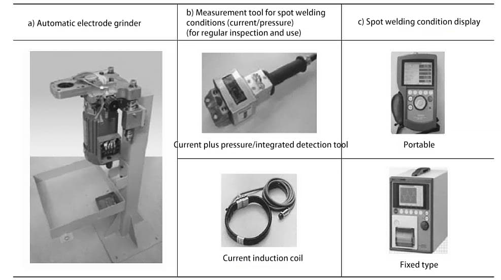
The current detector is an instrument used for controlling the quality of spot welding. It can be utilized to periodically check the current output of the spot welding controller, as well as to monitor the current of every weld spot in real time during production. It also provides a readout of the current during spot welding, as shown in Table 2-9c. Note: The electrical current during spot welding and the applied pressure of the welding tongs are critical elements.
At the beginning of system calibration, operators must thoroughly test the current and pressure conditions of the welding equipment to ensure the smooth progression of subsequent operations.