I. Overview
Sprockets can be manufactured using various methods and materials. The manufacturing method and material should be chosen based on the required tooth profile accuracy and surface roughness, combined with other processes such as heat treatment, to achieve the necessary carrying power, operating speed, and service life of the sprocket.
Based on the contact and operation with the chain, sprockets are mainly classified into two categories—precision and semi-precision. These categories can be further subdivided by material and manufacturing method, with other classification factors including cost-effectiveness and the precision requirements of the sprockets for the chains they are paired with.
Roller chain and toothed chain sprockets are generally made of steel or cast iron with machined teeth, and the working surfaces of the teeth usually require very precise machining. Engineering steel chain sprockets are commonly made of steel or cast iron with flame-cut or cast teeth.
Flat top chain sprockets can be made of steel, cast iron, or plastic. Steel or cast iron sprockets are usually machined, while plastic sprockets are often molded. These are general cases. Exceptions are not uncommon, especially with engineering steel chain sprockets. However, regardless of how the teeth are processed, the most important aspect is that the chain and sprocket designs are compatible for working together.
Machined-tooth sprockets operate more smoothly and with less noise during rotation, and they are usually used for medium to high-speed transmission. Cast-tooth or flame-cut-tooth sprockets are low-cost and have sufficient life for low-speed transmission and conveying. Manufacturers offer the following types of sprockets.
II. Roller Chain Sprockets
1. Single-row precision roller chain sprockets
The ASME B29.1 standard specifies standard roller chain sprocket sizes, tolerances, and tooth profiles, which are discussed in related designs.
There are four types of sprockets in the ASME B29.1 standard:
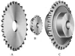
- Type A is a plate sprocket without a hub.
- Type B sprockets have a hub on one side only.
- Type C sprockets have hubs on both sides.
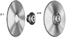
- Type D sprockets have detachable hubs.
Types A, B, and C roller chain sprockets are shown in Figure 1; Type D roller chain sprockets are shown in Figure 2.
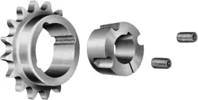
Another design of detachable hub sprocket is shown in Figure 3. It is a combination of a sprocket with a tapered bore and a split taper bushing. This design allows for the use of a finished sprocket with a standard bore to be matched with a shaft clamp drum. Types B and C sprockets can also be made this way.
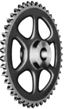
The spokes between the hub and the rim come in several forms depending on size: small sprockets are usually solid except for the center hole due to their light weight; medium-sized sprockets are usually cast with perforated spoke plates between the hub and rim (Figure 4) to reduce weight; large sprockets are usually cast as spoked sprockets (Figure 5) to minimize weight as much as possible. If the sprocket must be installed between two bearings, split sprockets (Figures 6 and 7) can be used, and their installation and removal do not involve disassembling the shaft.

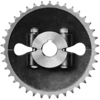
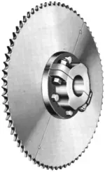
Some Type D sprockets consist of a solid hub and a detachable sprocket body (Figure 2). Others have both the hub and the sprocket body in sectional form (Figure 7). Any detachable sprocket must be carefully manufactured to prevent pitch variation at the joint, and the sprocket shown in Figure 7 is specifically designed with locating pins for this purpose.
A sprocket designed with a safety pin and sliding clutch can prevent transmission devices or other equipment from damage during overload and overspeed. The safety pin sprocket consists of a hub and sprocket body, with the hub connected to the shaft by a key. When the safety pin breaks (see Figure 8), the sprocket can rotate freely relative to the shaft and hub.
The safety pin is made of material with a known shear strength, ensuring a certain shear value by machining a groove with a calculated diameter on the shear plane. After shearing, inserting a new safety pin can restore it to working condition.
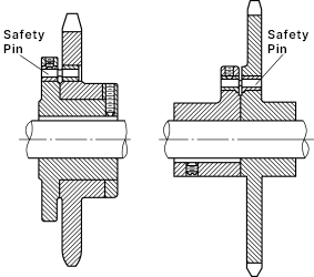
Figure 8 Hub with safety pin sprocket
2. Multi-strand roller chain sprockets
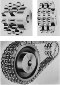
Multi-strand roller chain sprockets are integral sprockets with a certain pitch and aligned teeth. A typical multi-strand roller chain sprocket is shown in Figure 9.
3. Double-pitch roller chain sprockets
There are two types of double-pitch roller chain sprockets: one is single-cut (see Figure 10), and the other is double-cut (see Figure 11). The term “effective teeth” refers to the number of teeth that can mesh with the chain in one revolution of the sprocket.
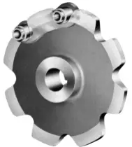
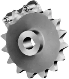
The effective number of teeth on a single-cut sprocket is equal to the actual number of teeth, while the effective number of teeth on a double-cut sprocket is half the actual number of teeth. For double-cut sprockets with an odd number of teeth, the effective number of teeth will be a fraction. For example, a sprocket with 25 actual teeth will have 12 (1/2) effective teeth.
The advantage of having an odd number of actual teeth is that each tooth only meshes with the chain every other revolution, thus doubling the lifespan of the sprocket. Double-cut sprockets with an even number of actual teeth can achieve the same effect by regularly moving the chain forward to the first tooth on the sprocket. Note that sprockets equipped with carrying-type rollers (translator’s note: i.e., large rollers) are insufficient.
Compared to single-pitch chain sprockets, double-pitch roller chain sprockets have a larger pitch diameter and root diameter. However, when the number of sprocket teeth exceeds 35, this difference can be ignored.
4. Roller chain sprocket machining
Smaller sprockets are generally machined from steel bar stock and are fully precision machined. The size of sprockets machined from bar stock is limited by the maximum diameter of the batch of bar material. Sprockets made of steel can be heat-treated to improve impact resistance and tooth surface wear resistance. For highly corrosive conditions, materials such as stainless steel or bronze can be used, as well as bakelite, nylon, and various plastic materials.
Sometimes sprockets are made from forged steel or forged bar stock. The machining precision depends on the specific requirements of the application. Many sprockets are made by welding steel hubs onto plate wheels, and such integral sprockets can only be heat-treated if the size proportions meet the requirements.
Large roller chain sprockets are usually made of cast iron, and these cast sprockets are machined to cut teeth, and the rim, hub, outer surface, and holes are also machined. Cast iron is often used to make large sprockets with a relatively large transmission ratio because the large sprocket teeth mesh with the chain less frequently over a certain period. In harsh conditions, it is better to use cast steel or steel plate sprockets.
III. Sprockets for toothed chains
The ASME B29.2 standard specifies the tooth profile for sprockets for toothed chains. The machining process, materials, and hubs for toothed chain sprockets are the same as those for roller chains, but the tooth profiles are significantly different, as shown in Figure 12.
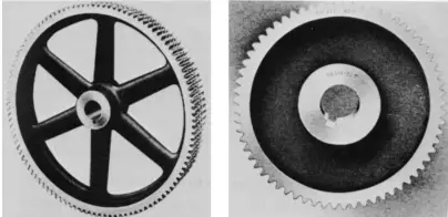
The teeth of the sprocket for toothed chains are similar to the teeth of gears. Although they look like gears, the sprockets for toothed chains are machined with special tools, which are different from the tools used for machining gears. In addition, the tooth profile of the sprocket and the chain pitch size also vary among different types of toothed chains.
Standard toothed chains use sprockets specified by the ASME B29.2 standard. However, there are also some non-standard toothed chains, such as high-performance, multi-strand, and double-sided engagement toothed chains. These non-standard chains often require specially machined sprockets.
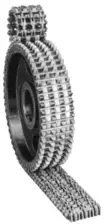
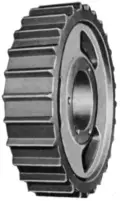
It is crucial for the chain and sprocket to match each other perfectly, so the best approach is to consult the chain manufacturer for specific technical requirements of the sprocket. A typical multi-strand toothed chain sprocket is shown in Figure 13, and a typical double-sided engagement toothed chain sprocket is shown in Figure 14.
IV. Engineering Steel Chain Sprockets
Sprockets for engineering steel chains can be made from various metals, come in various styles, and have many shapes to suit specific application requirements. For most applications, standard sprockets can be used.
There are many engineering steel chains that do not conform to ASME standards, and accordingly, there are many such sprockets. Most of them are very similar to standard sprockets, and when standard sprockets do not meet the needs, many of these sprockets can be used with standard chains.
The sprockets listed in this chapter are mainly used with standard chains or chains that have been slightly modified from standard chains, while the special sprockets in the manufacturer’s product catalog are certainly more numerous.
V. Sprocket Materials
The following materials are commonly used to manufacture sprockets for engineering steel chains:
- Cast iron: Usually used in milder environments, it is the most economical.
- Chilled cast iron: This type of sprocket uses chilled iron to cast the teeth. Chilled iron teeth are formed by rapidly cooling the tooth surface after casting, resulting in smooth and hard teeth with a wear-resistant hard layer that is 1/16 to 3/8 inches thick, depending on the sprocket size.
- Cast iron or structural steel: Cast iron sprockets have cast teeth, while structural steel sprockets have flame-cut teeth. Both are used for high torque and high impact transmission. When working in highly abrasive environments, the teeth need to be flame or induction hardened.
- Stainless steel: Used in corrosive environments.
More materials such as ferroalloys, alloy steels, bronze, and aluminum can be used to meet special needs.
1. Types of Cast Iron Sprockets
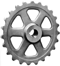
Casting sprockets with spoke-style hubs (Figure 15) can reduce weight and cost. This also makes it easier to handle by hand. Structural steel sprockets also serve the same purpose by flame cutting holes in the web, as shown in Figure 16.
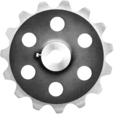
If the spoke space is too small, a solid sprocket is made (Figure 17). Additionally, solid sprockets are also made when the chain tension is high and there is concern about the strength of the spoked sprocket, or when the hub diameter is very large.
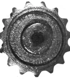
When the sprocket must be installed between two bearings, sometimes a split sprocket is made (Figure 18). This type of sprocket can be installed and removed without affecting the shaft and other machine parts.
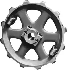
The removable tooth ring (Figure 19) is bolted on, and this sprocket design allows it to be installed and removed without having to disassemble the chain, hub, bearing, or shaft.
2. Friction traction wheel
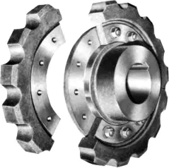
When the system often encounters obstacles or is severely overloaded, a friction traction wheel (Figure 20) can be used on the head shaft of a single-strand chain bucket elevator. However, friction traction wheels must always be used with caution. The friction between the chain and the traction wheel must be sufficient to transmit the driving force required by the working system under normal load. Consult the engineering steel chain manufacturer when using traction wheels.
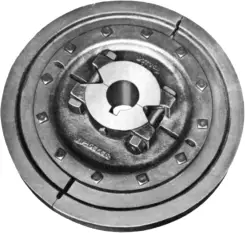
Friction traction wheels can generate heat and sparks when slipping, so they must never be used in places where sparks could cause explosions.
3. Engineering steel chain sprockets for specific applications
Figure 21 shows a set of special sprockets for specific applications, which are usually made of cast iron, and the teeth often have a quenched wear-resistant surface.
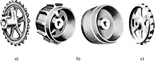
a) Sprocket with safety pin
b) Cylindrical flange sprocket
c) Sprocket with shoulder flange
The cast iron sprocket with a safety pin in the hub shown in Figure 21a is similar to the roller chain sprocket shown in Figure 8. They are commonly used in conveyor drive systems.
The two sprockets shown in Figure 21b are used for steel welded traction chains in traction conveyors, both are drive sprockets. The purpose of the sprocket flanges extending into wide edges or cylindrical shapes is to prevent material from spilling from the sides when unloading from above the drive shaft of the conveyor.
The shoulder flange on the sprocket shown in Figure 21c supports the chain plates at the drop point, extending the working life of the chain and sprocket. They are usually used on clean conveyors. These quenched cast iron sprockets are often designed to be “tooth-changeable,” functioning like the double-cut tooth sprockets of roller chains (Figure 11).
When designing such sprockets, the sprocket pitch is slightly larger than half the pitch of the chain, and the sprockets are cast with an odd number of teeth. After another turn of the chain link, the teeth are changed to mesh. This means that each tooth of the sprocket meshes with the chain every other turn, effectively doubling the lifespan of the sprocket (this concept was first used in wooden gear transmissions in the early 19th century).
4. Engineering steel bent plate drive chain sprockets
Engineering steel bent plate drive chain sprockets are usually made of cast iron, or flame cut from steel plates. Other parts like hubs are typically assembled components. The ASME B29.10 standard specifies the standard sprocket tooth form.
The sprocket in Figure 22 is paired with a double-row chain that conforms to the ASME B29.10 standard with a pitch of 6 inches for double-row drive chains. These sprockets use the American national standard tooth profile. Machined tooth profiles ensure the alignment of double-row heavy-duty chains. These sprockets are made of alloy steel and are heat-treated.
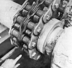
Bent plate chain sprockets do not always use machined teeth; many bent plate drive chain sprockets use cast or flame-cut teeth. There are many types of tooth forms. For non-machined teeth that do not use the ASME B29.10 standard, consult the chain manufacturer.
5. Other types of engineering steel chain sprockets
From the above discussion, we know that there are many types of sprockets available for various engineering steel chains. It seems that as long as the tooth form and size are appropriate, these chains can operate on various sprockets, but this is not the case.
In some applications, certain types of sprockets cannot be used with certain types of chains. For example, roller chains cannot use traction wheels. Generally, a certain type of sprocket is always used with specific chains. All other types of sprockets are also used only under specific conditions.
Table 1 lists the most commonly used sprocket types for the engineering steel chains described in this book. This table is not a guide on how to use them but shows general usage.
Table 1 Common sprocket types for standard chains
| Chain types | Standard roller chains | Sprocket chains | ||||||||
| B29.1 roller chains | B29.1 heavy-duty or bent plate chains | B29.1 multi-row roller chains | B29.1 double-pitch chains | B29.1 double-pitch conveyor chains | B29.1 large roller double-pitch conveyor chains | Plate chains | All models of B29.2 | |||
| Types of sprockets | Cutting gear teeth, finishing contact surfaces | Bar stock | ● | ● | ● | ● | ○ | □ | ● | ● |
| Composite steel parts | ● | ● | ○ | ● | ● | ● | □ | □ | ||
| Cast iron spoke or plate style | ● | ● | ● | ● | ● | ● | □ | ● | ||
| Cast iron, split design | □ | □ | □ | □ | ○ | ○ | □ | □ | ||
| Flame-cut gear teeth and contact surfaces | Plate steel assemblies | □ | □ | □ | □ | ○ | ○ | □ | — | |
| Removable tooth ring style, cast iron or assembly | □ | □ | □ | □ | □ | □ | □ | — | ||
| Heat-treated traction wheel | — | — | — | — | — | — | — | — | ||
| Cast iron, solid or spoke style, or with weight reduction holes in the web | □ | □ | — | □ | □ | □ | — | |||
| Cast gear teeth and contact surfaces (most can use a split design) | Chilled hard cast iron, hardened gear teeth | □ | □ | — | □ | □ | □ | — | ||
| Chilled hard cast iron detachable tooth ring, bolted to cast iron or assembly | — | — | — | — | — | — | — | — | ||
| Carbon or alloy steel, heat treated | □ | □ | — | □ | □ | □ | — | |||
| Cast iron traction wheel | — | — | — | — | — | — | — | |||
| Integral tooth ring, chilled hard cast iron or cast iron, heat treated alloy steel | — | — | — | — | — | — | — | |||
| Chain types | Rollerless straight plate chain | Roller chain | Non-roller bent plate chain | Conveyor large roller bent plate chain | Steel welded engineering chain | Welded steel traction chain | Steel cottered chain | Block chain | B29.10 Heavy-duty drive bent plate chain | ||
| Types of sprockets | Cutting gear teeth, finishing contact surfaces | Bar stock | — | □ | □ | □ | □ | — | □ | □ | — |
| Composite steel parts | — | □ | □ | □ | □ | — | □ | ○ | □ | ||
| Cast iron spoke or plate style | — | □ | □ | □ | □ | — | □ | ○ | □ | ||
| Cast iron, split design | — | □ | □ | □ | — | □ | □ | □ | |||
| Flame-cut gear teeth and contact surfaces | Plate steel assemblies | ● | ● | ● | ● | ● | ○ | ○ | ● | ● | |
| Removable tooth ring style, cast iron or assembly | ○ | ○ | ○ | ○ | □ | □ | □ | ○ | □ | ||
| Heat-treated traction wheel | ○ | — | ○ | — | □ | □ | □ | — | — | ||
| Cast iron, solid or spoke style, or with weight reduction holes in the web | ○ | ● | ○ | ● | ○ | ● | ● | ○ | ○ | ||
| Cast gear teeth and contact surfaces (most can use a split design) | Chilled hard cast iron, hardened gear teeth | ● | ● | ● | ● | ○ | ○ | ○ | ● | ||
| Chilled hard cast iron detachable tooth ring, bolted to cast iron or assembly | ○ | ○ | ○ | ○ | □ | □ | □ | □ | □ | ||
| Carbon or alloy steel, heat treated | ○ | ○ | ○ | ○ | □ | □ | □ | □ | ○ | ||
| Cast iron traction wheel | ○ | — | ○ | — | □ | □ | □ | — | — | ||
| Integral tooth ring, chilled hard cast iron or cast iron, heat treated alloy steel | ○ | — | ○ | — | — | — | — | — | — | ||
Note: ●—commonly used; ○—frequently used; □—occasionally used; dash (—)—should not be used.
Both circular and square symbols indicate usability, but there are differences between the two. The circular symbol means that this type of sprocket is completely standard for the listed chains and these standard sprockets are often listed in the manufacturer’s product catalog. Here, “commonly used” and “frequently used” often involve reasons related to price and quality.
The square symbol indicates that the sprocket is only occasionally or not suitable for the listed chains. The main reason for “occasionally used” is generally cost, but the main reason for “should not be used” is usually technical factors. Any pairing of chains and sprockets represented by a square symbol should only be installed after consulting the relevant chain manufacturer.
VI. Flat top chain sprockets
The tooth profile of flat top chain sprockets is specified in the ASME B29.17 standard and will be discussed later in the design section of this chapter. This section only involves the standard flat top chain sprockets described in this book. Since the only flat top chain mentioned in the book has a pitch of 1 (1/2) in, the styles of sprockets discussed here are quite limited.
Figure 23 shows three types of sprockets widely used for flat top chains. Figure 23a is an integral sprocket, which usually has fewer teeth (13–21 teeth) and can be made of cast iron, steel, or stainless steel, generally with machined teeth.
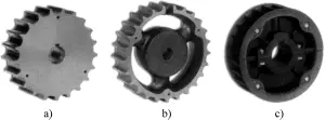
a) Integral sprocket
b) Spoked cast iron sprocket
c) Thermoplastic split sprocket
Figure 23b is a spoked cast iron sprocket, which generally has more teeth (19–41 teeth) and is also usually machined.
Figure 23c is a thermoplastic split sprocket, which typically has a medium number of teeth (21–29 teeth) and standard molded teeth. The advantage of this type of sprocket is that it can be disassembled without moving the shaft and bearings. Molded thermoplastic sprockets can be made in split or integral styles, mainly used in wet or moderately corrosive environments.

