How to Fix Welding Deformation: Effective Techniques and Tips
Few things are as frustrating in the world of welding as dealing with unexpected deformation. Whether you’re working on a…
Imagine you’re about to start your first welding project, but you’re unsure how to adjust your welding machine settings. It might seem daunting at first, but mastering these adjustments is crucial for achieving strong, clean welds. From understanding voltage and amperage to interpreting welding charts, this step-by-step guide will walk you through the entire process. You’ll learn how to tweak your machine based on material thickness, ensuring your welds are precise and effective. We’ll also delve into wire feed speed, a critical factor that can make or break your welding success. Ready to make those perfect welds? Let’s dive in and discover how to fine-tune your welding machine for optimal results.
In welding, voltage is the measure of the electrical potential difference between the electrode and the workpiece. This parameter influences the arc length and the shape of the weld bead. Higher voltage results in a longer arc and a wider, flatter bead, while lower voltage produces a shorter arc and a narrower, more concentrated bead.
Amperage, or current, is the flow of electrical charge through the welding circuit. It directly affects the heat input to the weld and the depth of penetration. Higher amperage increases the melt-off rate of the electrode or wire, leading to deeper penetration and a higher deposition rate. However, excessive amperage can cause burn-through, especially on thin materials.
Voltage and amperage are connected factors that must be balanced for optimal welding performance. While voltage controls the arc length and bead shape, amperage dictates the heat input and penetration depth. Adjusting these parameters correctly ensures a stable arc, proper fusion, and minimal defects in the weld.
Understanding and adjusting voltage and amperage is crucial for achieving high-quality welds. Proper settings help prevent common issues such as undercut, lack of fusion, and burn-through.
By understanding and correctly adjusting voltage and amperage, welders can achieve optimal results, ensuring strong, defect-free welds suitable for various applications.
Welding charts are crucial tools that offer detailed guidelines on the necessary welding parameters for different joints and materials. They help welders set up their machines correctly, ensuring high-quality welds. Understanding how to interpret these charts is essential for achieving optimal welding results.
Welding symbols are graphical representations that convey specific welding instructions. For example, the arrow symbol points to where the weld should be applied, acting as a guide to the joint. The reference line contains vital information such as weld size, depth, and pattern. It can be single-sided or double-sided, showing different welds on each side of the joint. The weld symbol represents the type of weld, such as fillet or groove weld.
Understanding the different types of welds and their corresponding symbols is essential for accurate interpretation:
Welding charts provide recommended settings for voltage, amperage, and wire feed speed (WFS) based on the material type and thickness. Here’s how to use these charts effectively:
Welding charts vary depending on the material being welded, with specific recommendations for settings like voltage, amperage, and WFS.
Material thickness is crucial in welding because it directly affects your welding machine settings. It refers to the measurement of how thick the material being welded is, typically in inches or millimeters. Thicker materials need more heat for proper penetration, whereas thinner materials require less heat to prevent burn-through.
The material’s thickness dictates the voltage, amperage, and wire feed speed (WFS) settings on your welding machine, which must be adjusted correctly to ensure a strong, clean weld without defects. Here’s how each parameter is influenced by material thickness:
Welding charts are useful tools that offer recommended settings for different materials and thicknesses. Here’s how to use them effectively:
Accurately adjusting your welding machine settings based on material thickness ensures high-quality welds with proper penetration and minimal defects.
Wire Feed Speed (WFS) is the speed at which the welding wire is fed through the torch during welding. It is measured in inches per minute (ipm) and significantly affects the quality of the weld.
Correct WFS is essential for proper weld penetration and appearance, ensuring a consistent and defect-free weld bead. If the WFS is too high, it can result in burn-through and excessive spatter. Conversely, if the WFS is too low, the weld may suffer from poor penetration and a wider, less defined bead.
Several factors influence the appropriate WFS setting:
Thicker materials require higher wire feed speeds to achieve adequate penetration, ensuring the weld is strong and properly fused.
Different wire sizes necessitate specific WFS settings. Common wire sizes include .023, .030, and .035 inches. Each size requires adjustments in WFS to match the desired amperage and weld characteristics.
The speed at which the welding torch is moved affects the required WFS. Faster welding speeds need higher WFS to maintain a consistent weld pool and deposition rate.
Experienced welders can adjust WFS settings based on the appearance of the weld bead for optimal results.
Begin by familiarizing yourself with the concept of WFS and its impact on weld quality. Recognize that WFS controls the rate at which the welding wire is fed into the weld pool.
To calculate WFS, use a multiplier based on wire size. For instance, .030-inch wire typically uses 2 inches per amp. So, at 125 amps, the WFS would be around 250 ipm.
Observe the characteristics of the weld bead, such as penetration, bead profile, width, and tie-in at the edges. Adjust the WFS accordingly to achieve the desired weld quality.
Voltage and WFS are interdependent. Adjusting one often necessitates adjusting the other to maintain the balance required for a high-quality weld.
Use a stopwatch or digital timer to measure the amount of wire fed over a set time, such as 6 seconds. Calculate the ipm by multiplying the measured length by ten.
Some welding machines may have inaccurate digital readouts; physical measurements can ensure a more accurate WFS setting.
Continuously monitor the weld bead and make incremental adjustments to the WFS as needed to maintain consistency and quality.
Keep a log of successful WFS settings for future reference. This practice helps streamline the adjustment process for similar projects.
Understanding and accurately adjusting wire feed speed allows welders to optimize machine settings to produce high-quality welds with proper penetration and minimal defects.
Arc length refers to the distance between the welding electrode and the workpiece, and adjusting it is essential for controlling the heat and quality of the weld. A shorter arc length results in a more concentrated heat zone, leading to a narrower weld bead, which is ideal for welding thin materials to prevent burn-through. Conversely, a longer arc length spreads the heat over a wider area, producing a broader weld bead suitable for welding thicker materials where deeper penetration is needed.
Weld penetration refers to the depth that the weld fuses into the base material. Proper penetration ensures the strength and durability of the weld. High penetration, achieved by increasing the amperage, results in deeper fusion into the base material, necessary for structural welds where strength is critical. Low penetration, achieved by reducing the amperage, leads to shallower fusion, suitable for cosmetic welds or thin materials.
Maintain a consistent travel speed and arc length, using a push or pull method depending on the joint type. This process is ideal for welding thin to medium-thickness materials, including steel and aluminum.
Use a precise, controlled arc with a non-consumable tungsten electrode, adding filler material manually. This technique is best for welding thin materials and intricate joints, providing high-quality, clean welds.
Utilize a flux-coated electrode, maintain a short arc length, and use a consistent travel speed. This method is suitable for outdoor welding and thicker materials, providing strong, durable welds.
Ensure proper alignment and fit-up. Use a weaving motion to fill the joint evenly. This joint type is commonly used in structural applications where two pieces are joined edge to edge.
Overlap the pieces and use a zigzag or circular motion to ensure thorough fusion. This technique is ideal for joining two pieces with one overlapping the other, often used in sheet metal work.
Maintain a steady hand to fill the corner evenly, using a short arc length for precision. This joint type is used to join two pieces at a right angle, common in frame construction.
In the flat position, weld from above the joint, allowing gravity to assist in forming a smooth bead. This is the easiest and most common position, suitable for most welds. In the vertical position, use a weaving motion to prevent the weld pool from dripping and adjust settings to reduce heat input. This challenging position is often used in structural welding where vertical joints are required.
Use a short arc length and lower amperage to control the weld pool, working in small sections to avoid excessive heat. This position requires skill and precision, used in situations where welding from below is necessary.
Gas Metal Arc Welding with Constant Voltage (GMAW-CV) power supply is an essential component in welding processes that ensures a stable and consistent voltage output. This stability is crucial for maintaining the quality and integrity of welds across various applications.
The power supply in GMAW-CV systems plays a pivotal role in controlling the welding parameters. It determines the voltage, which affects the arc length and overall weld bead profile. Proper adjustment of the power supply settings ensures that the welds are strong, defect-free, and meet the required specifications.
Choosing the correct welding voltage is the first step in setting up a GMAW-CV power supply. Here’s how to select the appropriate voltage:
Wire Feed Speed (WFS) indirectly controls the welding current, making it crucial in GMAW-CV welding. Follow these steps to adjust the WFS:
Although the welding current is not directly set in GMAW-CV systems, it is influenced by the WFS adjustments. Here’s how to monitor and control the current:
A correct Contact Tip to Work Distance (CTWD) ensures stable arc conditions. Follow these guidelines:
Travel speed impacts the weld bead profile and penetration. Here’s how to adjust it:
The welding current influences the metal transfer mode. For instance, above approximately 190 amps, the transfer mode can shift from globular to spray, depending on the metal and shielding gas used. Adjust settings to achieve the optimal transfer mode for your application.
Choosing the appropriate shielding gas is critical for protecting the weld area from atmospheric contamination. Different gases, such as argon or CO2, are used based on the material and desired weld quality. Ensure proper gas flow rates and mixtures to maintain weld integrity.
By understanding and correctly adjusting GMAW-CV power supply settings, welders can optimize their welding processes, achieving high-quality, reliable welds across various applications.
When welding, various issues can arise that affect the quality and integrity of the weld. Here are some common problems and their causes:
Spatter occurs when small droplets of molten metal are ejected from the welding arc, creating imperfections on the weld surface.
Causes:
Solutions:
Porosity refers to the presence of small holes or voids in the weld bead, which can weaken the weld.
Causes:
Solutions:
Distortion occurs when the welded material warps or bends due to uneven heat distribution.
Causes:
Solutions:
Lack of fusion is when the weld does not adequately bond with the base metal, leading to weak joints.
Causes:
Solutions:
Undercut is a groove formed at the weld toe, reducing the cross-sectional area of the weld and compromising its strength.
Causes:
Solutions:
Overlap occurs when excess filler metal spills over the edge of the weld, creating a weak joint.
Causes:
Solutions:
To troubleshoot these issues, it’s essential to adjust your welding machine settings correctly:
Adjusting wire feed speed and voltage helps achieve the right balance for your weld. Too high or too low settings can cause spatter or porosity.
Adjust the gas flow rate to prevent porosity, based on the material and welding conditions.
Adjust amperage and voltage to achieve proper fusion without causing distortion or undercut. Monitor the heat input to ensure it matches the material thickness and welding requirements.
By following these steps and making necessary adjustments to your welding machine settings, you can improve the quality of your welds and effectively resolve common welding issues.
Below are answers to some frequently asked questions:
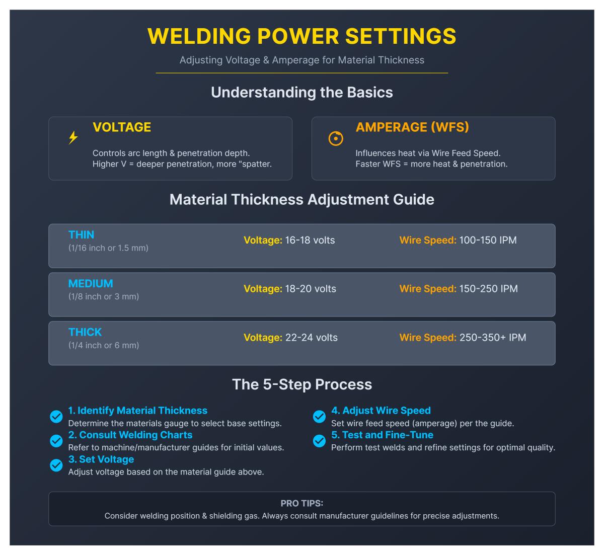
Adjusting voltage and amperage for different material thicknesses is essential for effective welding.
Voltage controls the arc length and penetration depth. Higher voltage results in deeper penetration but may cause more spatter. Amperage, regulated by wire feed speed, influences the heat input into the weld. Faster wire speed increases heat input and penetration.
Here’s how to adjust settings based on material thickness:
Consider welding position and shielding gas, as these factors can affect settings. Consult manufacturer guidelines for precise adjustments.
If the wire feed speed is too high during welding, several issues can occur. Firstly, the wire may stub into the workpiece instead of forming a smooth arc, leading to poor weld penetration and a rough bead surface. Additionally, increased wire feed speed raises the current (amperage), which can cause excessive heat input if not balanced with appropriate voltage and travel speed. This excessive heat can result in a wide bead and potential damage to the material. To manage these problems, it is crucial to balance the wire feed speed with proper voltage settings, travel speed, and shielding gas to ensure a quality weld.
Reading a welding settings chart is essential for setting up your welding machine correctly. These charts provide guidelines based on various factors such as material thickness, wire diameter, and shielding gas type. To read a welding settings chart effectively, follow these steps:
By following these guidelines, you can adjust your welding machine settings to achieve optimal weld quality for your specific project. Always test on scrap metal first and fine-tune settings as needed.
For beginners in welding, mastering basic techniques is essential for producing quality welds and understanding how to adjust welding machine settings effectively. Here are some common welding techniques for beginners:
By practicing these techniques and understanding how to adjust machine settings, such as voltage, amperage, wire feed speed, and shielding gas flow, beginners can enhance their welding skills and achieve better results. Safety measures, proper ventilation, and starting with simple projects are also crucial for beginners to build confidence and ensure a safe welding environment.
To prevent burn-through on thin materials, you need to carefully manage heat input and adjust your welding techniques. Firstly, reduce the current setting on your welding machine to minimize the amount of heat applied, as excessive heat can cause thin metals to melt and create holes. Completing welding passes quickly also helps reduce heat exposure.
Choosing the right electrodes and filler metals is crucial. Opt for smaller electrodes that require less heat, which is better suited for thin materials. Maintain a moderate arc length, ideally equal to the diameter of the electrode, to prevent concentrating too much heat in one spot.
Adjust your travel angle and welding speed to ensure you don’t apply too much heat in one area. Using a weave technique can help distribute heat evenly across the weld area. Additionally, ensure your materials are clean and free from contaminants to achieve a quality weld without defects.
Using appropriate shielding gases, like argon/CO2 blends, can help control the arc and heat input, further reducing the risk of burn-through. By following these steps, you can effectively prevent burn-through and achieve high-quality welds on thin materials.
If your welds are not penetrating properly, start by increasing the amperage within the recommended range for your material thickness and electrode type. Higher amperage helps melt the base metal more effectively, improving penetration. Additionally, maintain a short arc length by holding the electrode closer to the workpiece, which concentrates heat and enhances penetration.
Slowing down your travel speed can also help, as faster speeds might cool the weld pool prematurely, causing shallow penetration. Ensure you are using the correct electrode for your material, with smaller diameters for thin materials and penetrating types like E6010 for DC root passes.
Proper joint preparation, including maintaining appropriate root gaps and cleaning the base material to remove contaminants, is essential for effective heat transfer. If you are using MIG or TIG welding, adjust the shielding gas mixture to enhance penetration. Lastly, verify your electrode angle, maintaining a slight drag angle to direct heat toward the weld root.