Understanding Turning Centers in Precision Engineering
Imagine a world where the slightest deviation in manufacturing could compromise the integrity of an entire product. Precision engineering, the…
Imagine you’re starting a new project in CAD, but you’re unsure how to set up your drawing frames and borders correctly. This step-by-step guide is designed to help you navigate the world of CAD drawing frame sizes and standards with ease. Whether you’re wondering about the standard sizes for CAD drawing frames, the appropriate line thickness for borders, or the common sheet sizes used in architectural and engineering drawings, this guide has got you covered. We’ll break down each concept, from understanding the BS EN ISO 5457 standard to setting up title blocks and sheet margins. By the end, you’ll have practical tips and insights to ensure your CAD drawings are up to industry standards. Ready to dive in and master the essentials of CAD drawing frames? Let’s get started!
CAD drawing frames are standardized boundaries surrounding the main content of technical drawings. These frames help to organize information, provide space for annotations, and ensure that all necessary details are included in a consistent format.
Borders are essential in CAD drawings as they delineate the working area, maintain a clean and professional look, and ensure all relevant information is contained within the defined space. Borders also include important information like the project name, date, and drawing number.
The dimensions of CAD drawing frames are typically based on standard sheet sizes. These sizes are compatible with printers and facilitate easy handling and storage. Here are some common standard sizes:
| Size | Dimensions (mm) | Common Use |
|---|---|---|
| A4 | 210 x 297 | General documents and drafts |
| A3 | 297 x 420 | Larger technical drawings |
| A2 | 420 x 594 | Detailed architectural plans |
| A1 | 594 x 841 | Large-scale architectural plans |
| B4 | 250 x 353 | Specialized technical drawings |
In CAD software, drawings are typically created at full scale (1:1) in model space. This practice allows for precise representation of dimensions and features without scaling issues. When printing, the drawings can be scaled down to fit standard sheet sizes while maintaining their original proportions.
Borders define the edges of the drawing area and typically include space for notes, titles, and other relevant information. Standardized border templates are available in most CAD software, ensuring that all drawings adhere to a consistent format.
The title block is a critical component of the drawing frame, usually located at the bottom or side of the sheet. It contains essential information such as the project name, drawing number, date, and the name of the drafter. This information helps in identifying and managing drawings efficiently.
Understanding and implementing CAD drawing frames and borders effectively is essential for producing professional and standardized technical drawings.
BS EN ISO 5457 is a guideline that outlines the size and layout of preprinted sheets for technical drawings, ensuring consistency and clarity across engineering fields. Understanding this standard is essential for producing professional and compliant technical drawings.
The standard specifies a 20mm wide border on the left side for filing, and 10mm wide borders on the top, right, and bottom sides. These borders help in organizing the drawing and provide space for filing and annotations.
The frame around the drawing space should have continuous lines that are 0.7mm thick, ensuring all technical details are contained within this area.
To ensure accurate positioning during reproduction or microfilming, four centring marks are recommended at the ends of the two symmetry axes of the sheet. These marks aid in precise alignment.
Although not directly specified in the 1999 version of the standard, earlier versions suggest the use of a grid reference system. This system includes grid lines that should be at least 0.5mm thick, with reference labels using capital letters along one edge and numerals along the other edge for easy referencing.
When creating CAD drawings, adhering to BS EN ISO 5457 ensures standardization and clarity. Here are some best practices:
By following these guidelines, you can create clear, organized, and compliant technical drawings that adhere to the BS EN ISO 5457 standard.
Line weights, also known as line thicknesses, are crucial in CAD drawings for distinguishing various elements and ensuring clarity.
Using the correct line thickness for drawing borders helps frame and highlight the design effectively, with heavy line weights like 0.50 mm or thicker typically used for prominent elements such as exterior walls and architectural features. In landscape drawings, 0.6 mm is often chosen for building outlines and borders to create a clear boundary.
Medium line weights, ranging from 0.35 mm to 0.50 mm, are used for walls, floors, and structural elements in section views, providing a balance between visibility and detail without overwhelming the drawing.
When plotting drawings at half size, avoid using very fine lines to maintain readability. Use pen tables to adjust line weights for different scales, ensuring clarity.
In the USA, standards like ASME Y14.5 and Y14.5M offer guidelines for line weights in technical drawings, ensuring consistency and clarity across various types of drawings.
In the UK, BS 8888 and BS 1192 provide similar guidance to maintain uniformity in technical drawings.
Consistency in line weights throughout a drawing is crucial for maintaining visual clarity, helping viewers quickly understand the drawing and locate key elements. Adjust line weights according to the plot scale to ensure readability, using thicker lines for smaller scale drawings if necessary. Utilize established pen tables to manage line weights when plotting at different scales, maintaining consistency and clarity regardless of the drawing size.
Software like gCADPlus allows for precise control over line thicknesses for different elements in a drawing, essential for creating clear and detailed designs that adhere to established standards.
ANSI sizes are crucial for anyone working with technical and engineering drawings. ANSI, the American National Standards Institute, provides widely used standard sheet sizes in the United States, especially important for technical and engineering drawings.
Arch sizes are primarily used in architectural drawings, providing larger formats ideal for building plans and construction details.
Although both ANSI and Arch sizes are used for technical drawings, they serve different purposes. ANSI sizes are more standardized for engineering and technical purposes, whereas Arch sizes are tailored for architectural and construction drawings.
Title blocks in CAD drawings provide essential information about the project, including the drawing title, author, date, and scale. Setting up title blocks correctly ensures that all necessary details are easily accessible and the drawing maintains a professional appearance.
Title blocks serve multiple purposes:
There are two main methods for creating a title block in CAD software:
Margins ensure the drawing content isn’t cut off during printing and provide a clean boundary around the drawing area.
Following these steps and best practices will help you set up title blocks and sheet margins in CAD drawings, ensuring clarity, consistency, and a professional look for your projects.
CAD standards are a set of predefined rules that organize drawings, covering aspects like layer naming, dimension styles, text fonts, line types, and drawing frame sizes. Adhering to these standards ensures uniformity across all drawings in a project, which facilitates efficient collaboration and review.
Select a drawing frame size that matches common paper sizes like A0, A1, A2, A3, and A4, based on your geographical standard (ISO, ANSI, etc.). Ensure the frame size comfortably fits your drawing details without overcrowding or leaving too much whitespace. The physical size of the detail should be proportionate to the sheet size to fit the border and title block appropriately.
Title blocks should include essential information such as the project name, drawing title, scale, date, and revision number. To avoid clutter, maintain a separate title block with a detail grid system. Each detail should fit into one or more grid spaces without overlapping to keep the layout organized. Consistent title blocks help in quick identification and referencing of drawings.
Draw your design in Model Space at a real-world scale, and use Paper Space to set up the drawing frame and viewports. Set viewports to the appropriate scale that matches your dimensioning and detail requirements. Place all elements like title blocks, borders, and annotations in Paper Space to prevent scaling issues when printing.
Follow a strict layering convention where each type of object, such as dimensions, text, lines, and hatches, is placed on a specific layer with predefined color, linetype, and lineweight settings. Arrange drawing elements in the correct order, such as placing dimension lines on top of geometry lines, to avoid confusion during reading. Use BYLAYER properties for color, linetype, and lineweight to maintain consistency and ease of changes.
Use standardized dimension settings such as arrow size, extension line length, text height, and alignment. For example, an arrow size might be set to 1/8 inch, text height to 3/32 inch, with text placed above and centered to the dimension line. Dimension units, precision, and zero suppression should conform to project or regional standards (e.g., architectural units with 1/16” precision). Text styles should be clear and consistent, using a standard font and size, with text colors set to BYLAYER.
Before finalizing the layout, make sure all details and annotations fit within the designated frame and grid spaces without overlap or excessive blank areas. Adjust sizes and scales as necessary to ensure legibility and proper alignment with the title block and border.
Document your CAD standards in a clear, accessible manual covering frame sizes, title block design, layer naming, dimension styles, and plotting instructions. Train users and integrate these standards into CAD templates to ensure consistent application across all projects.
Below are answers to some frequently asked questions:
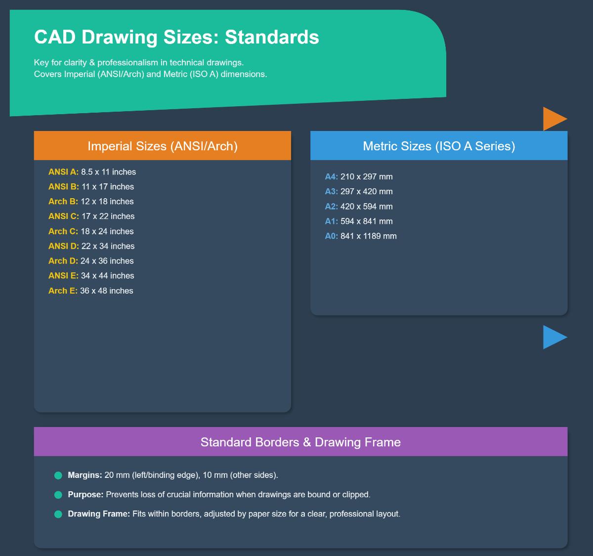
Standard sizes for CAD drawing frames and borders are essential for ensuring clarity, consistency, and professionalism in engineering and architectural drawings. These sizes typically correspond to standard paper dimensions, which are divided into Imperial (ANSI/Architectural sizes) and Metric (ISO A series).
For Imperial sizes, common dimensions include:
For Metric sizes, commonly used dimensions are:
Standard borders typically have a 20 mm margin on the left (binding edge) and 10 mm margins on the other three sides. This setup ensures no essential information is lost when drawings are bound or clipped. The drawing frame, where the actual content is placed, fits within these borders, adjusted according to the paper size to maintain a clear and professional layout.
For drawing borders in CAD, the recommended line thickness is generally 0.7 mm. This thickness is considered the thickest lineweight and is typically used for borders and title blocks in technical drawings. Using a 0.7 mm line ensures clarity and emphasis, differentiating the border lines from other elements in the drawing. This standard aligns with guidelines such as the BS EN ISO 5457, which is commonly followed in engineering and architectural documentation. Adopting this line thickness helps define the drawing sheet clearly, making it easier to read and file, thus ensuring your CAD drawings maintain a professional and standardized appearance.
The title block, which contains essential project information such as the project title, location, project number, date issued, and organization details, should be placed in the lower right corner of the CAD drawing sheet. This placement is a standard practice to ensure consistency and easy reference across various drawings. The specific size and arrangement of the title block may vary depending on the CAD standards being followed. Consistency in using the same title block format and placement across all drawings is crucial for maintaining a standardized process.
Common standard sheet sizes used in architectural and engineering drawings are crucial for ensuring clarity and consistency across projects. In architectural drawings, the most frequently used sizes in the U.S. include ARCH A (9 x 12 inches), ARCH B (12 x 18 inches), ARCH C (18 x 24 inches), ARCH D (24 x 36 inches), and ARCH E (36 x 48 inches). These sizes are well-suited for construction plans and large format documents.
For engineering drawings, the ISO A series is widely used internationally, including sizes such as A0, A1, A2, and A3. These sizes are based on the ISO 216 standard, ensuring global consistency. In the U.S., ANSI sizes may also be used, though they are more common for general office documents.
Using these standardized sizes helps maintain organization, consistency, and facilitates better communication and collaboration among architects, engineers, and contractors.
To ensure your CAD drawing layout complies with industry standards, start by familiarizing yourself with common guidelines like the United States National CAD Standard (NCS), which provides comprehensive rules on drawing orientation, layout, symbols, and line types. Follow these key steps:
Additionally, developing a comprehensive guide for your organization’s CAD standards, providing regular training, and periodically updating the standards to reflect industry changes will help maintain compliance. Resources like Autodesk University and the National CAD Standard (NCS) offer valuable guidance and examples.
When setting up CAD drawings according to standards, there are several tools and software options available that can help ensure compliance. AutoCAD is the most widely recognized CAD software, offering extensive tools for both 2D and 3D drafting, and it supports common file formats like DWG and DXF, facilitating standard adherence. DraftSight Professional is another versatile option, providing a familiar interface and advanced features such as layer management and dimensioning to maintain drawing standards. SmartDraw is user-friendly, with built-in templates and symbols for various engineering and architectural standards. Creo, developed by PTC, is robust for complex designs and ensures engineering standards compliance, particularly in the automotive and mechanical sectors. Lastly, Alibre Atom3D is a beginner-friendly software that supports 3D modeling and design, making it suitable for newcomers to CAD drafting. These tools help streamline the process of creating CAD drawings that meet industry standards, improving efficiency and collaboration.