Comprehensive Fine Blanking Tutorial: Step-by-Step Guide
Imagine a metal forming technique so precise that it transforms raw material into intricate components with unrivaled accuracy. Welcome to…
Are you ready to take your automation projects to the next level by mastering the setup of a servo driver? Whether you’re an intermediate hobbyist or a professional looking to fine-tune your skills, this comprehensive step-by-step tutorial will guide you through the entire process. From understanding the essential components and preparing your workspace, to wiring your servo motor and integrating it with a PLC, we’ve got you covered. We’ll delve into the nitty-gritty of configuration, ensuring your servo driver operates smoothly and efficiently. By the end of this guide, you’ll not only know how to connect a servo motor to a servo driver but also how to troubleshoot common setup issues. Ready to dive in and unlock the full potential of your servo systems? Let’s get started!
Servo drivers play a vital role in controlling servo motors, which are essential in applications like robotics, automation, and CNC machines. They convert low-power control signals into high-power signals necessary for precise motor operation. This section provides an overview of the components involved and the initial steps required for setting up a servo driver.
A servo motor typically has three wires: power, ground, and a signal wire, which receives command pulses to control the motor’s position, speed, and direction.
The servo driver converts control signals from a controller, such as a PLC or microcontroller, into the high-power signals needed to drive the servo motor, ensuring precise positioning and movement.
In automation systems, a PLC is commonly used to control servo drivers by sending precise command signals based on its programmed logic.
A reliable power supply is essential for both the servo driver and the motor. The power supply must match the voltage and current requirements specified by the servo driver and motor.
In some setups, an analog servo drive may be used, which operates with analog signals for control. This type of drive is suitable for applications requiring smooth and continuous control.
Before beginning the installation, gather all necessary tools and materials, such as wiring diagrams, connectors, and safety equipment. Adhere to all safety precautions to avoid electrical hazards and ensure a successful setup.
By understanding these components and preparing adequately, you can proceed with confidence to wire and configure your servo driver system.
A servo driver is a key component in servo motor systems that converts low-power control signals into high-power signals to drive the motor. It ensures precise control over the motor’s position, speed, and torque by receiving commands from a controller, such as a PLC (Programmable Logic Controller) or a microcontroller, and translating these commands into actions by adjusting the power supplied to the servo motor.
The servo motor is an actuator that converts electrical signals into precise mechanical movements, typically consisting of a rotor, stator, and an encoder or resolver for feedback. The motor operates based on the control signals received from the servo driver, allowing for accurate control of angular or linear position, velocity, and acceleration. Servo motors are commonly used in applications requiring high precision, such as robotics, CNC machinery, and automation systems.
A PLC is a specialized computing device used in industrial control systems to automate processes. In servo systems, a PLC sends control signals to the servo driver and can be programmed to perform tasks like coordinating multiple motors and responding to sensor inputs. It acts as the brain of the automation system, ensuring that the servo motors operate in a synchronized and efficient manner.
The power supply is a crucial component that provides the necessary electrical power to the servo driver and motor. It must match the voltage and current requirements specified by the servo driver and motor to ensure stable and reliable operation. Power supplies can be either DC (like 24V or 48V) or AC, depending on the servo system’s requirements. Proper selection and installation of the power supply are essential to prevent issues such as voltage drops, overheating, and electrical noise.
An analog servo drive is a type of servo driver that operates using analog signals for control. Unlike digital servo drives, which use digital communication protocols, analog servo drives receive continuous voltage or current signals to control the motor’s operation. This type of drive is suitable for applications requiring smooth and continuous control, such as certain types of machining and process control. Analog servo drives are often used in older systems or specific industrial applications where smooth, continuous control is preferred.
Before starting the installation, gather all the necessary tools and materials to ensure a smooth and efficient setup. Here is a checklist of essential items:
Ensuring safety during the installation process is paramount. Follow these guidelines to prevent accidents and protect both personnel and equipment:
Understanding the specifications of your servo drive, motor, and associated components is crucial for a successful installation, so follow these steps:
Ensuring the servo drive, motor, and controller are compatible is essential for seamless operation. Here are the key aspects to verify:
Servo motors are crucial for automation systems, offering precise control of mechanical movements. A typical servo motor used in hobbyist and industrial applications features three primary connectors:
Connecting a servo driver to a PLC involves several critical steps to ensure seamless communication and control. Follow these steps to properly integrate your servo driver with a PLC.
Make sure both the servo driver and the PLC are powered off before making any connections. This precaution helps prevent electrical hazards and protects the devices from potential damage.
Collect all necessary cables, connectors, and software. Commonly required items include communication cables (e.g., Ethernet, RS-232, or RS-485), power cables, control signal cables, and the manufacturer’s manuals and wiring diagrams.
Refer to the specific connection diagram provided by the manufacturer of your PLC and servo driver. This diagram will illustrate the exact wiring scheme needed for your setup, ensuring all connections are correctly made.
Configuring a servo driver requires setting up various parameters to ensure the servo motor operates correctly and efficiently.
Select the control mode using the servo drive’s interface, software, or keypad. Check the manual for specific instructions.
Configure the motor type by accessing the servo drive’s settings and selecting the appropriate motor type from the available options.
A stable and adequate power supply is crucial for the reliable operation of the servo system. Ensure that the power supply matches the voltage and current requirements specified by the servo driver and motor.
DC Servo Drives typically operate at 24V, 48V, or higher, depending on the application. AC Servo Drives require AC input, commonly 220V or 380V, depending on the region and application. Ensure the power supply can provide sufficient current to handle the peak and continuous current demands of the servo motor. Check the servo drive and motor specifications to determine the exact requirements.
Properly setting parameters is vital for the optimal performance of the servo system. Key parameters include:
Gain settings include Proportional Gain (P) for response speed, Integral Gain (I) for eliminating steady-state errors, and Derivative Gain (D) for stability. Start with the manufacturer’s recommended values and adjust as necessary during testing.
These settings help in protecting the motor and ensuring smooth operation.
Many servo drives come with software tools for advanced configuration and tuning. Follow the manufacturer’s instructions to install the software and connect your computer to the servo drive using the appropriate interface (e.g., USB, Ethernet). Use the software to adjust parameters, monitor performance data, and diagnose issues.
Testing ensures that the servo system operates correctly under actual working conditions.
Make adjustments to the configuration as necessary based on the test results. Always refer to the manufacturer’s guidelines for specific testing procedures and recommended adjustments.
First, locate the power terminals on your servo driver. These terminals are typically marked for easy identification, such as terminal 35 providing 24 volts and another terminal serving as an activation signal.
Ensure the power supply matches the voltage and current requirements specified by the servo driver, then connect the positive and negative terminals of the power supply accordingly. Secure all connections to prevent any loose wires, which could cause electrical faults.
Some servo drivers require a specific activation signal to start the motor. This could be a positive or negative signal, depending on the model. Refer to the servo driver’s manual for detailed information on the required activation signal.
Once the power connections are secure, send the activation signal to the correct terminal. This signal can be generated by a PLC or another control device. Ensure that the signal voltage matches the servo driver’s specifications to avoid any damage.
Use the jog mode on the servo driver to manually test the servo motor’s movement. Jog mode allows you to move the motor incrementally to verify if it responds correctly to control signals. This is an essential step to ensure that the motor is functioning properly before running automated sequences.
Check for indicators like green lights or status displays on the servo driver. These indicators will confirm whether the servo driver is ready and operational. Any error indicators should be addressed immediately by checking the connections and configurations.
Use output signals from your controller to send pulse signals to the servo driver. These pulses determine the motor’s position or speed. Ensure that the control signals are properly configured and match the servo driver’s requirements.
Some servo drivers offer options for 5V or 24V control signals. Choose the appropriate voltage based on your setup, and use necessary resistors for protection. Incorrect voltage levels can damage the servo driver or motor.
Choose the mode that best suits your application, such as position, velocity, or torque mode, and set the drive accordingly. For example, if using EtherCAT communication, ensure the drive is set to the correct mode.
If your application requires position tables, configure the servo driver with the correct lookup table settings. This can typically be done using software tools provided by the servo driver manufacturer.
Before powering up the servo system, ensure that all components are securely fastened. Loose components can lead to mechanical failures or electrical short circuits.
Double-check that all voltage levels match the specifications of your equipment. Incorrect voltage levels can cause significant damage to the servo driver and motor.
If the servo motor does not respond as expected, verify all connections. Ensure that power, ground, and control signal connections are secure and correctly aligned.
Refer to the servo driver’s manual for troubleshooting guides specific to your model. The manual will provide detailed steps for diagnosing and resolving common issues.
After completing the setup and activation steps, confirm that the servo driver and motor operate as intended. Run a series of tests to ensure that all parameters are correctly set and the system performs reliably under expected conditions.
Implement a regular maintenance schedule to check the servo driver and motor for any signs of wear or damage. Regular maintenance helps in prolonging the life of the equipment and maintaining optimal performance.
Periodically inspect and clean the servo drive to remove dust and debris.
Keep the firmware updated to ensure compatibility and optimal performance.
Provide training for operators and technicians to ensure correct handling and operation of servo systems, minimizing errors.
If troubleshooting steps fail to resolve the issue, it may indicate a deeper hardware or software problem. Contacting the servo drive manufacturer or a professional technician is recommended. Provide detailed fault information, including error codes and operating conditions, to expedite the resolution process.
Below are answers to some frequently asked questions:
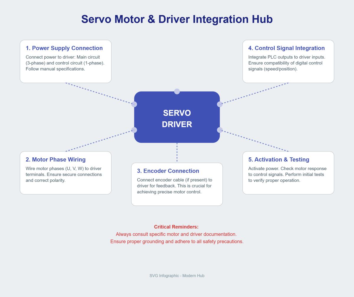
To connect a servo motor to a servo driver, follow these steps:
Always consult the specific documentation for your servo motor and servo driver to ensure compatibility and correct procedures. Proper grounding and adherence to safety precautions are essential.
To set up a servo driver, follow these steps:
By following these steps, you can successfully set up a servo driver for your project. Always refer to the specific documentation for detailed instructions and safety precautions.
To integrate a servo driver with a PLC, follow these steps:
First, ensure that both the PLC and the servo drive are powered off to prevent electrical hazards. Gather all necessary components, including the PLC, servo drive, appropriate communication cables, and software. Verify that the servo drive and PLC are compatible, particularly regarding communication protocols like Ethernet, RS-232, or RS-485.
Next, connect the power supply to both devices, ensuring proper grounding to minimize electrical noise. Use the appropriate communication cable to connect the PLC’s communication port to the servo drive’s corresponding port. Then, connect the PLC’s output signals to the servo drive’s input terminals, typically for control commands such as speed and position.
Once all connections are made, power on both the PLC and servo drive. Configure the PLC software with the correct communication parameters, including baud rate, data bits, and parity. Write a control program in the PLC to send commands to the servo drive, which may involve setting up position control or velocity control modes. Test the connection by sending simple commands to verify proper communication and control.
If issues arise, check that all cables are secure and correct, and review the communication settings on both devices. Refer to the manuals of the PLC and servo drive for specific troubleshooting instructions. Ensure the servo motor is properly connected to the servo drive, and verify that the PLC outputs are compatible with the servo drive’s input requirements.
By following these steps, you can successfully integrate a servo driver with a PLC, ensuring precise and reliable control of the servo motor.
Common issues when setting up a servo driver often stem from wiring errors, incorrect configuration, and power supply problems. Loose or incorrect wiring can lead to the servo motor not turning or generating abnormal noises. Ensure all connections are secure and follow the motor phasing correctly, particularly for three-phase motors. Overheating issues can arise from overloads or improper settings; check the load and review controller parameters to ensure they are set correctly. Communication errors between the servo driver and PLC can result from faulty wiring or incompatible settings, requiring inspection of connections and software updates. Overcurrent, overvoltage, or undervoltage errors typically indicate power supply issues or incorrect settings; measure voltage and current at the motor terminals and review the configuration. Regular maintenance and documentation of any changes in settings or wiring can help prevent and quickly resolve these common issues.